
Abstract
In this article, tube hydroforming along with stamping, a compound forming technology of thin-walled tube using stamping and hydroforming processes, was presented to cut forming costs, reduce number of forming and assembly operations, and improve forming efficiency. A simple experimental tooling was designed and manufactured. Forming experiments of stamping and tube hydroforming along with stamping processes in two square cross-section dies were performed for SS304 tubes at different upper die velocities. The experimental results indicated that the better formability and the more uniform thickness distribution are obtained by the tube hydroforming along with stamping processes than by the stamping.
Keywords
Introduction
Tube hydroforming (THF) is one of the most popular forming processes for thin-walled tube which achieves remarking development in automotive and aircraft industries. In contrast with conventional manufacturing methods, the THF offers several advantages, such as weight reduction through more efficient section design, lower manufacturing and tooling costs, fewer secondary operations, and improved structural strength and geometry accuracy.1–3 Formability, one of the most important parameters in the THF, is affected by forming method, internal pressure, loading paths, material property and friction force,4,5 and therefore many studies on formability and optimization of the THF processes have been reported in recent years.
Hwang and Altan 6 proposed a forming method of regular triangular cross-section tubes by crushing combined with THF. In this article, the experimental devices were designed, and the compound forming tests of crushing and hydroforming were carried out. The results showed that the new method would obtain the better formability than the hydraulic expansion process only. Yang and Guo 7 and Nikhare et al.8,9 adopted low-pressure THF technology to deform the thin-walled tube. Li et al. 10 presented a compound method of crushing and THF processes to form trapezoid-sectional tubes. The finite element (FE) models and experiments were proposed for the single-step hydroforming process and the crushing combined with THF. Compared with the single-step method, the forming pressure of the method was lower, and the thickness distribution was more uniform. Elyasi et al. 11 proposed a method of stepped tubes to improve the formability. Mori et al. 12 proposed a pulsating hydroforming process to improve the formability and prevent local thinning and wrinkling, and compared the forming property between pulsating and linear load. The results showed that the pulsating hydroforming would obtain better forming quality. However, the above-mentioned methods to improve the formability must depend on the internal pressure that comes from special pressurizing devices.
In the current research, tube hydroforming along with stamping (THS), a new forming method of thin-walled tubes, was proposed to reduce the number of forming and assembly operations, cut costs of bulging and pressurizing devices, and improve forming efficiency.
Materials and methods
Materials
SS304 tubular materials, commonly used for the THF processes, are investigated during validation of the project. The tubes are roll-formed and laser-welded without heat treatment. Dimensions and material properties of the tube are shown in Figure 1 and Table 1.
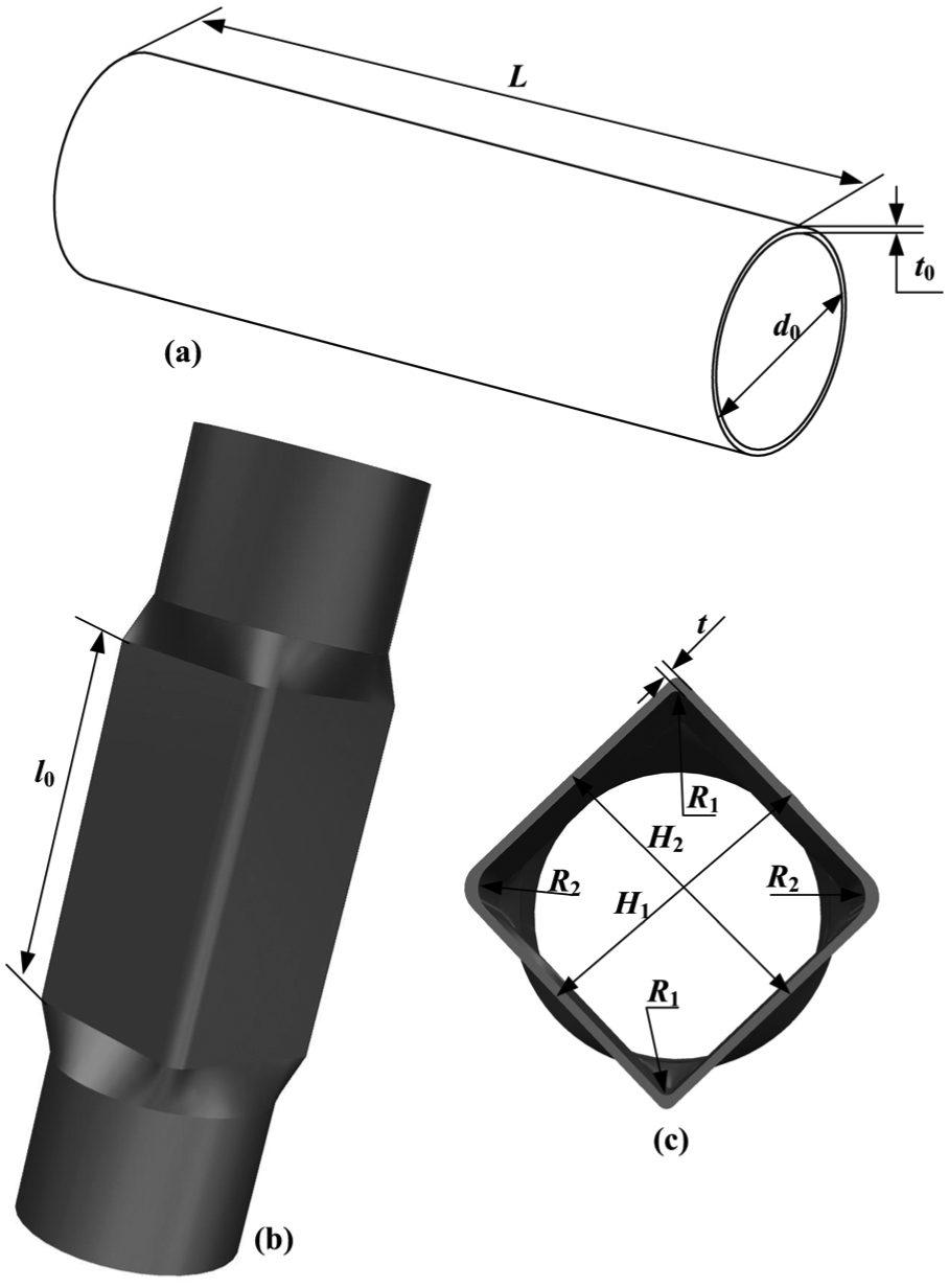
Dimensions of the thin-walled tube: (a) original tube, (b) formed tube and (c) sectional view.
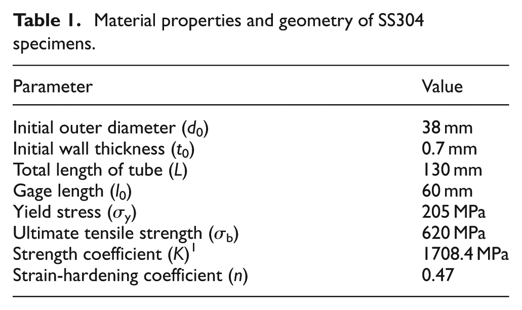
Material properties and geometry of SS304 specimens.
Forming methods
THS is a compound method of metal forming combined stamping and hydroforming to produce the complex cross-section tubes. The method does not replace either conventional stamping or hydroforming, but rather fills the gap between them.
The proposed THS process consists of injecting fluid, sealing tube, closing dies and forming. For the stage of injecting fluid shown in Figure 2(a), liquid from big fluid container is injected to the thin-walled tube. The initial internal pressure P0 is 0 MPa at the moment. During the stage of sealing tube shown in Figure 2(b), the left and right control valves are shut off when the liquid is filled into the tube. During the stage of closing dies shown in Figure 2(c), the upper and lower dies are stamped and closed gradually with the movement of press ram, and the internal pressure P1 recorded by pressure gauge is raised rapidly. During the stage of forming, shown in Figure 2(d), the tube is deformed and filled toward the interior surface of the die cavity under the internal pressure. When sections of upper and lower dies are thoroughly closed around the tube, the maximum internal pressure P2 appears and causes the tube to conform to the shape of the die cavity.
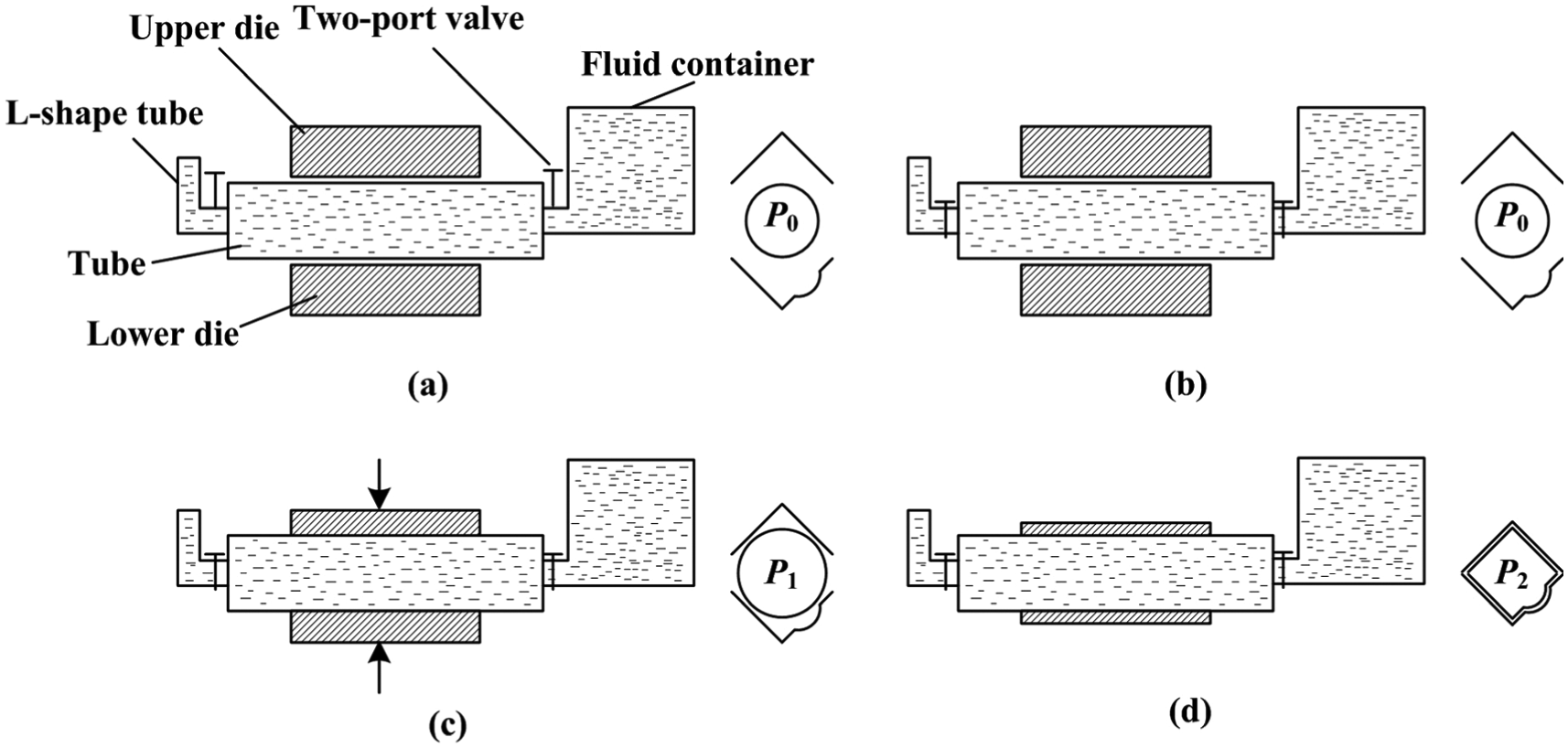
Forming stages of thin-walled tubes by the THS process: (a) injecting fluid, (b) sealing tube, (c) closing dies and (d) forming.
Experimental tooling
A simple and suitable equipment of THS was designed and manufactured in order to carry out the experimental campaign. The basic systems of the experimental tooling comprise stamping device and THF apparatus as shown in Figure 3.
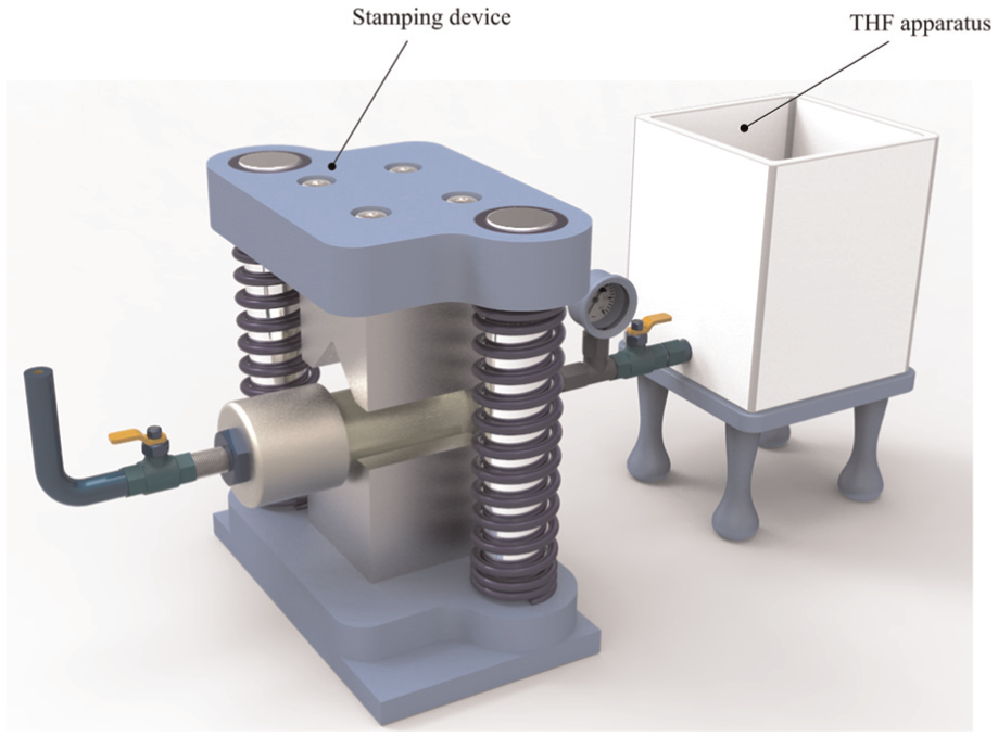
Experimental tooling of THS.
Stamping device
To obtain a desired shape using THS, the stamping device was designed. It consists of five parts, as shown in Figure 4, (1) upper and lower die plates, used to fix the upper and lower dies and install guide pillars; (2) upper and lower dies, the different die cavities should be designed to obtain different cross-section formed tubes; (3) two guide pillars and sleeves; (4) two captured springs and (5) socket head cap screws.
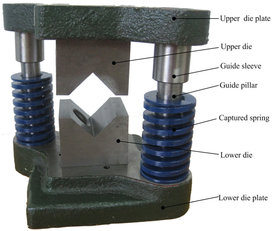
Stamping device for the THS process.
The stamping device is fixed on the worktable of stamping press. When the upper and lower dies are subjected to closing force from stamping press, they are closed gradually. Due to the reduction in the internal tube volume, the internal pressure is increased during the closing process.
To study the formability of stamping and THS processes, two square cross-section dies were designed: one was regular shaped called V-0 as shown in Figure 5(a), and the other was irregular shaped called V-1 as shown in Figure 5(b). V-0 is adopted for the stamping processes; V-0 and V-1 are used for the THS processes. The forming conditions for stamping and THS processes in two square cross-section dies are shown in Table 2.
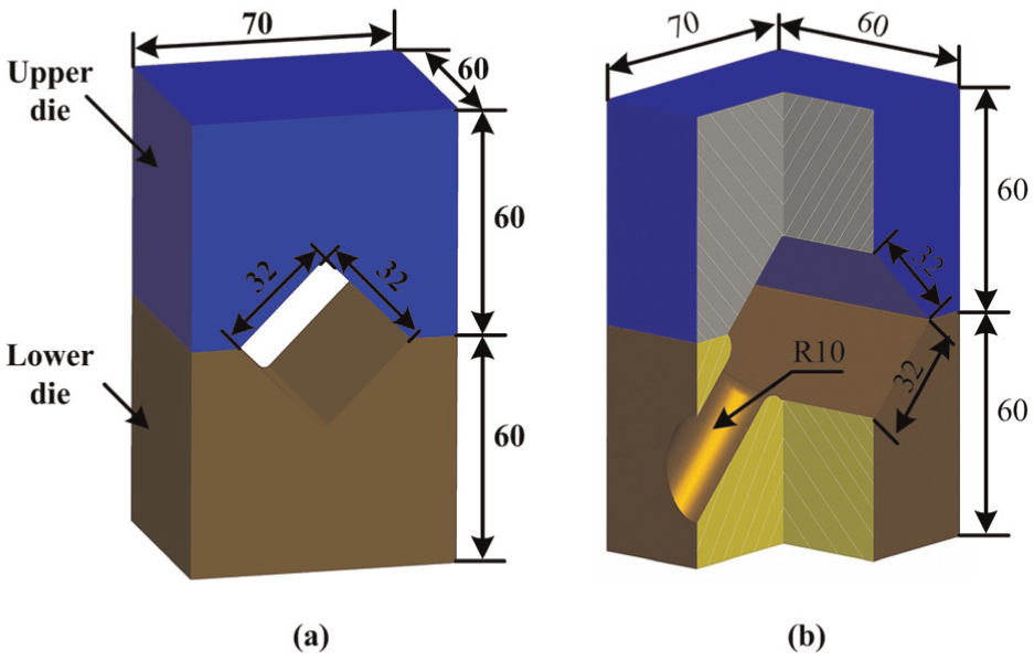
Configurations of (a) V-0 and (b) V-1 dies by the stamping and THS processes.
Forming conditions for stamping and THS processes in V-0 and V-1 dies.
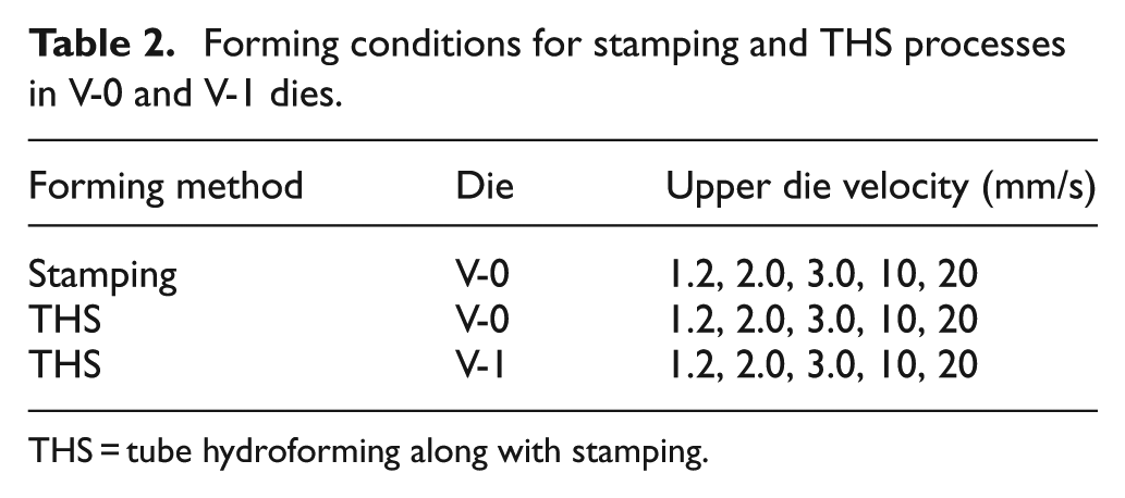
THS = tube hydroforming along with stamping.
THF apparatus
To fix and seal the thin-walled tube, supply liquid for hydraulic forming, the THF apparatus was designed as shown in Figure 6.
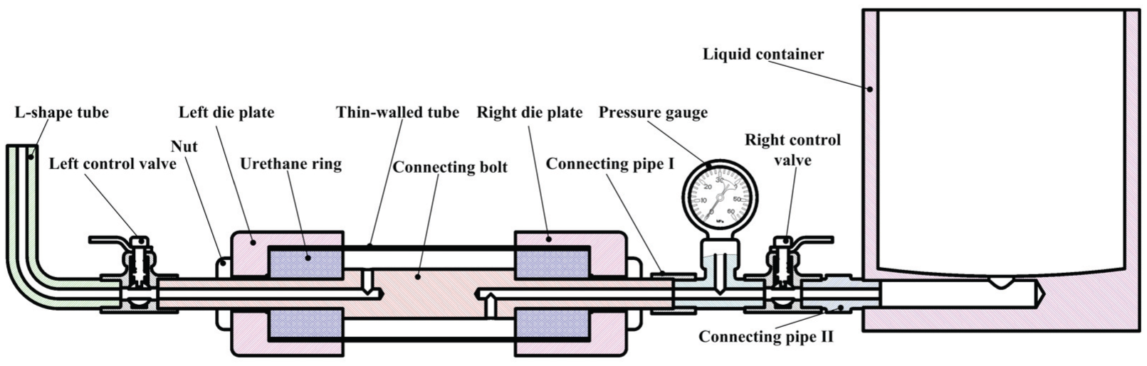
Schematic of THF apparatus for the THS process.
Left and right die plates are held together by connecting bolt. The tube contained the left and right die plates. Outer diameter and bulging length of the tube are confined by the inner diameter of the die plates and length of connecting bolt, respectively. Urethane rings are pushed into both ends of the tube to avoid leakage of the fluid. One end of the connecting bolt is connected to pressure gauge, right control valve and liquid container, and the other end is connected to left control valve and L-shaped tube. The liquid from liquid container flows to the tube through the right control valve and connecting bolt. When the liquid is filled with the cavity of the tube, it is overflowed from the L-shaped tube. At this time, the left and right control valves are closed, and the liquid is confined inside the tube.
Analytical approaches
After each experiment, the measurements of corner radius (R1 and R2), bulge height (H1 and H2) and thickness (t) were made with digital micrometer by sectioning the deformed tube symmetrically with wire cut electrical discharge machining (WEDM), as shown in Figure 1. All the measurements were made for three bugled tubes under the same experimental conditions, and the experimental data were averaged to cut down possible artificial errors.
Forming internal pressures
With the purpose of producing a part without any defect, two critical internal pressures, yield pressure (Piy) and burst pressure (Pib), must be determined first. According to Koç and Altan 13 and Fatemi et al., 14 Piy is obtained as
where σy, σ1 and σ2 are the yield, circumferential and axial stress, respectively. t0 and d0 are the initial wall thickness and outer diameter, respectively. In the current research, THS is performed without axial force, so axial stress σ2 is 0 MPa. Therefore, equation (1) can be rewritten as
P ib is obtained as
where σb is the ultimate tensile strength.
Free bulging experiments of THF were carried out to validate the Piy and Pib. The values of Piy and Pib from the experiments were 7.92 and 26.43 MPa, respectively; and they, from calculation, were 7.69 and 26.50 MPa, respectively. It is obvious that the experimental results of the Piy and Pib are well in accordance with equations (2) and (3); the slight differences are likely due to the measurement precision.
Relationship between perimeter and thickness
According to the dimensions of the original tube, initial perimeter of the deformation zone (S0), as shown in Figure 7(a), is expressed as

Cross-section dimensions of (a) original tube, (b) mold cavity and (c) formed tube.
The initial volume of the deformation zone (V) is obtained as

The perimeter of cavity section inside the upper and lower dies (S1), as shown in Figure 7(b), is expressed as

where a is the length of the mold cavity.
The formed tube perimeter of the deformation zone (
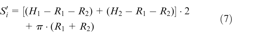
The formed tube volume of the deformation zone (

where
Under the assumption of constant volume, the following can be concluded

Equation (9) shows that
Relationship between internal pressure and volume of formed tube cavity
The internal pressure during the THS directly affects the filling of formed tubes, so it is very important to find a peak pressure which does not cause burst. Moreover, the peak pressure increases with increasing changes in volume (

where V0 and V1 are the initial volume of the tube cavity and the volume of the formed tube cavity at a given time, respectively.
In this study, elastic deformation of tube, liquid leakage, friction factors and gravitational potential energy are ignored. According to the energy conservation law, the output power of press at a given time (dW) can be expressed as

where
Therefore, liquid can be compressed when there is external force acting, the dV is deduced as

where β is the compressibility coefficient of liquid, and
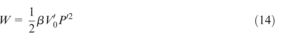
From equations (11) and (12), the output power of press at a given time can be calculated as

Equation (13) can be expressed by integration as
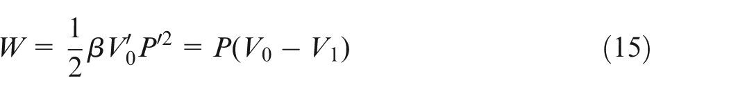
According to equations (10), (11) and (14)
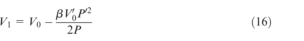
So, V1 can be expressed as
Results and discussions
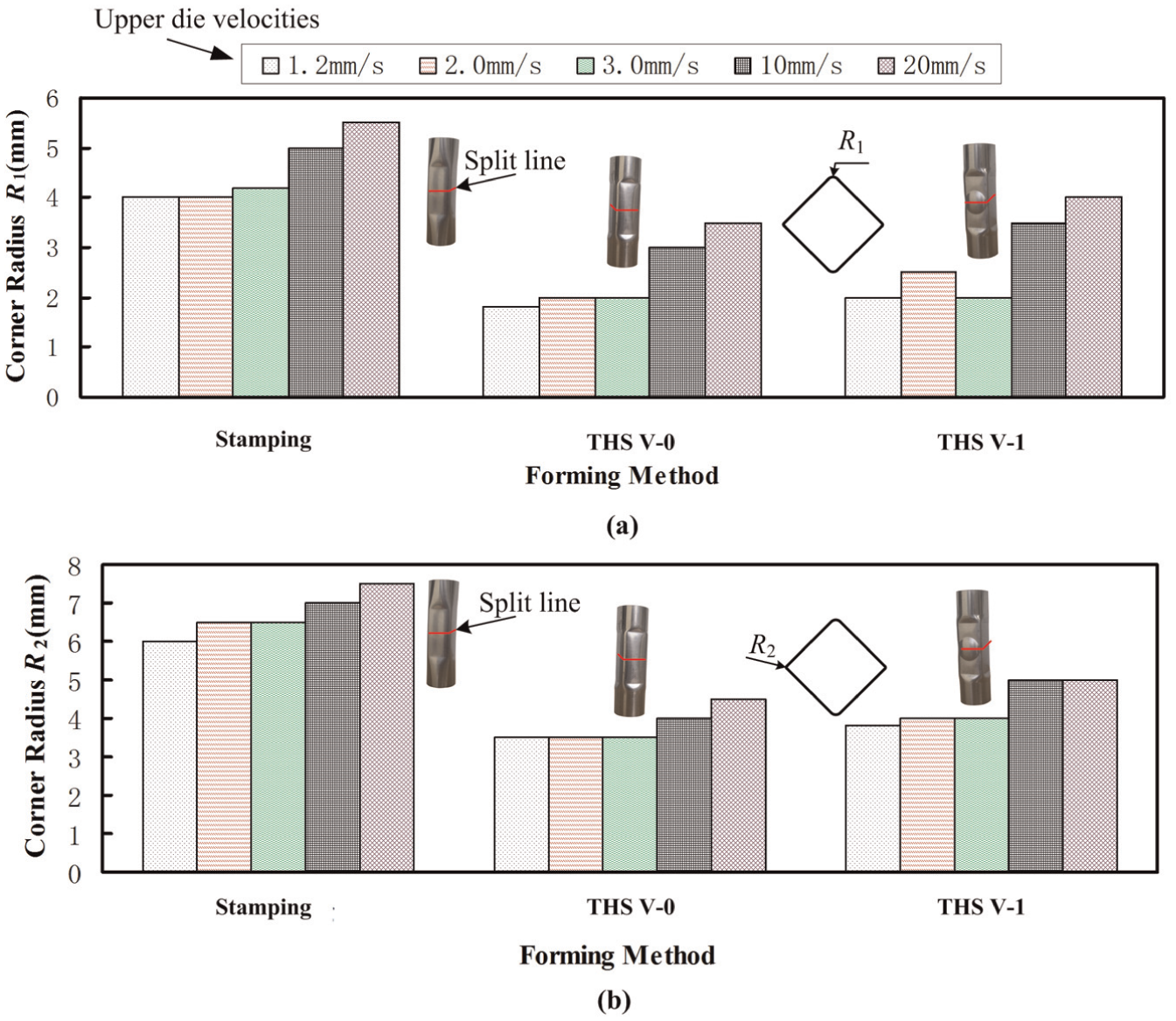
Figure 8 shows the formed tubes obtained via the stamping and THS processes under different upper die velocities. The influence of the stamping and THS processes on formability of the tubes is provided as follows, and the possible causes for the experimental results are presented in detail.
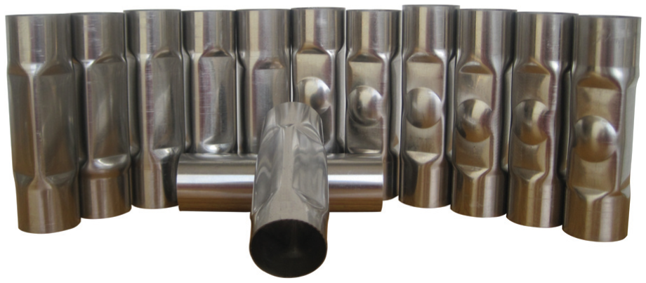
Tubes formed by the stamping and THS.
Effect of forming method on maximum pressure Pmax
The values of the maximum internal pressure for all the tubes obtained via the stamping and THS processes under the different upper die velocities were recorded, as shown in Figure 9. It can be seen from the chart that the internal pressure P (including Pmax) was 0 MPa in the stamping processes. There was no liquid inside the tube, so the internal pressure cannot be produced when the dies are closed under the different upper die velocities. However, the internal pressure was increased gradually when the lower and upper dies are closed in the THS processes. And the maximum pressure Pmax of V-0 and V-1 will emerge when the dies are closed completely. Because the compressed volume was constant, the Pmax of V-0 and V-1 was about the same level at the five upper die velocities; the highest and lowest Pmax were 26.2 and 25.8 MPa in V-0 and 25.3 and 24.8 MPa in V-1, respectively. The slight differences were likely to be caused by the measurement precision and the inevitable performance difference in the tubes. If a different maximum pressure Pmax is obtained, the cavity sizes of dies or initial sizes of tubes should be altered.
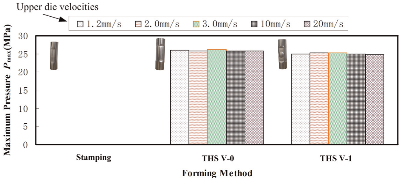
Comparison of the maximum pressure Pmax formed by the stamping and THS.
Effect of forming method on corner radii R1 and R2
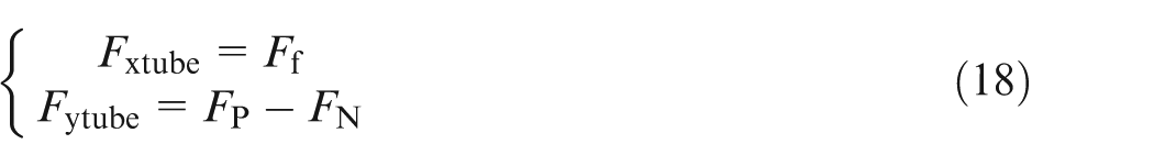
Figure 10 illustrates the comparison of corner radii R1 and R2 at the middle sections of the formed tubes by the stamping and THS processes. As shown in the figure, the corners of die cavity were not filled completely in the stamping process; the largest R1 and R2 were 5.5 and 7.5 mm and the smallest R1 and R2 were 4 and 6 mm, respectively. Nevertheless, in the THS V-0 and V-1, the corners of cavity were filled completely except two high upper die velocities of 10 and 20 mm/s; the largest R1 and R2 were 2.5 and 4 mm and the smallest R1 and R2 were 1.8 and 3.5 mm, respectively.
Comparison of (a) corner radius R1 and (b) corner radius R2 at the middle sections of the tubes formed by the stamping and THS processes.
The results show that the die corners are filled at low pressure by the THS process, and the formability in the THS is affected by the high upper die velocity, so it is very important to choose a reasonable upper die velocity to improve the efficiency and formability.
In the THS, the deformed tube and the dies subject to principal forces as shown in Figure 11, internal pressure FP from the tube, closing force F1 from the stamping press, positive pressure FN and friction force Ff between the tube and die. The force analysis of die can be expressed as
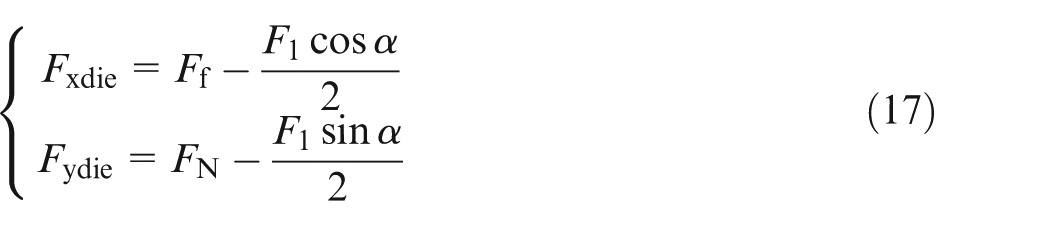
where Fxdie and Fydie are the resultant of forces in x-axis and y-axis to die.
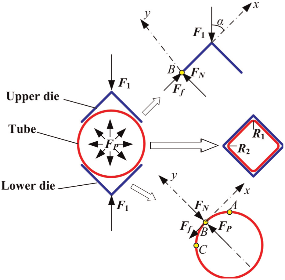
Diagram of forces on the deformed tube.
The force analysis of tube can be expressed as
where Fxtube and Fytube are the resultant of forces in x-axis and y-axis to tube.
And

where μ is the friction factor between the tube and die. Because the tube subjects to only the friction force Ff in the x-axis, it should cause material flow of tube from AB to BC region, resulting in the thickening at BC region and thinning at AB region. Furthermore, the thin tubular materials would possess better fallibility than the thick at the same internal pressure, so it leads to two different values of corner radii R1 and R2.
Effect of forming method on bulge heights H1 and H2
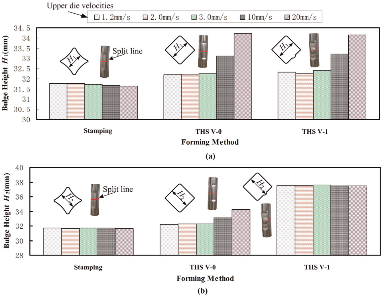
In order to further explore the formability of the stamping and THS processes, the bulge heights H1 and H2 at the middle cross-section of deformed tubes were studied as shown in Figure 12. From the chart, it was known that the maximum H1 and H2 are 31.78 and 31.72 mm by the stamping processes, respectively, but the ideal H1 and H2 were 32 mm. The geometry of deformed tubes does not conform to its shape of the die cavity, the main reason is that the tubular blank only subjects to the mold clamping and friction force without internal pressure. However, H1 and H2 of V-0 by the THS processes were slightly larger than 32 mm except two high upper die velocities of 10 and 20 mm/s, the largest deviation is 0.94%. The H1 of V-1 was slightly larger than 32 mm too. These slight deviations come from the spring-back of the tubular blank after opening dies at the upper die velocities, and the deviations should become larger and larger with increasing the upper die velocity. The profiles of standard and spring-back tubes are shown in Figure 13. Because the lower die of V-1 is designed with a hole, the diameter is 20 mm, the tubular blank will appear free bulging and fill into it at THS experiments. It was found from the figure that H2 of V-1 was a good agreement between 37.48 and 37.58 mm at the five speeds owing to the constant internal pressure. However, the deviations of bulge heights appeared due to creep deformation at the high upper die velocities.
Comparison of (a) bulge height H1 and (b) bulge height H2 at the middle sections of the tubes formed by the stamping and THS processes.
Profiles of (a) spring-back tube, (b) standard tube and (c) superimpose tubes.
Effect of forming method on thickness (t)
Figure 14 shows the thickness distributions of the thin-walled tubes at the middle cross-section after the stamping and THS processes. The initial wall thickness (t0) for the experiments is 0.7 mm. The formed tubes are symmetrical on the central vertical line, so the thickness distributions on the right side of the tube’s cross-section are studied as shown in Figure 14.
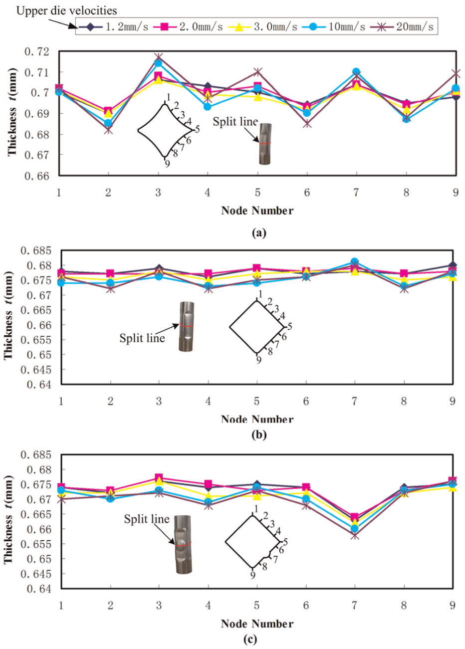
Comparison of thickness distributions by (a) stamping, (b) THS V-0 and (c) THS V-1 at the middle cross-sections of the parts formed.
From Figure 14(a), it was known that the thickness distributions are very non-uniform using the stamping processes; the maximum and minimum thickness were 0.717 and 0.682 mm at the five speeds, respectively. However, the thickness distributions of the formed products using THS processes were good agreement except NO.7 of THS V-1 due to the free bulging as shown in Figure 14(b) and (c). Of course, the thickness distributions are affected by the upper die velocity, and the thickness variation should become obvious with the increasing speed.
According to equation (9), the thickness of the formed tube will be affected under the different formed conditions. At the stamping processes, the thicknesses are more than the initial wall thickness (t0) in some areas, others are thinner. The reason is that each area of the tube withstands different stress states resulting in tensile or compress under the mold clamping force only. However, the thicknesses are thinned in every area because the tubes are bulged under the internal pressure inside the tubes and mold clamping force outside the tubes, and the stress states are same at the THS processes.
Conclusion
The THS was proposed to improve efficiency and reduce difficulty in the process of forming. A simple and practical experimental tooling was developed. The deformation of SS304 tube by stamping and THS processes into a square cross-section was investigated in the experiments. The comparisons of the maximum pressure P, corner radius R, bugle height H and thickness t of the formed products between stamping and THS were carried out. The following conclusions are obtained:
The proposed THS process, which consists of injecting fluid, sealing tube, closing dies and forming, successfully fabricated square tubular parts. Two critical internal pressures, yield pressure (Piy) and burst pressure (Pib), were obtained for the complete THS of tubes. The relationships between perimeter and thickness, and internal pressure and volume of formed tube cavity were analyzed, respectively.
The THS processes can produce constant internal pressure by itself when the upper and lower dies are closed, so it does not need the special pressurizing equipment. Moreover, the peculiar method of producing internal pressure should be less time with the higher upper die velocity, so the forming efficiency is improved quickly.
The smaller corner radius of the formed tubes was obtained due to the produced internal pressure in the THS processes than in the stamping. Moreover, the produced internal pressure increased the bulging height, thickness strain and equivalent plastic stress throughout the tube, so the bulge height of the formed tubes showed a good agreement with the square cross-section dies, and the thickness distribution of the formed products showed more uniform than by stamping processes by THS processes.
In future work, the effect of upper die velocity on flow stress and formability will be investigated further at the THS processes.
Footnotes
Declaration of Conflicting Interests
The author(s) declared no potential conflicts of interest with respect to the research, authorship and/or publication of this article.
Funding
The author(s) disclosed receipt of the following financial support for the research, authorship, and/or publication of this article: This work was supported by the National Natural Science Foundation of China (grant nos 51065006, 51271062), the Guangxi Natural Science Foundation (grant no. 2013GXNSFBA019245) and Science and Technology Research Projects of Guangxi Universities (grant no. KY2015YB095).