
Abstract
To an aircraft, the accuracy of aerodynamic configuration has a direct influence on flight performance. To improve the assembly accuracy of aircraft wing components, two kinds of positioning method and the corresponding assembly precision are studied, and a low-cost flexible assembly tooling system for different wing components is proposed. First, the article analyzes the technological characteristics of airplane wing skin and determines the assembly requirement. Second, positioning method based on contour boards and coordination holes and their assembly precision are researched. Third, to verify the positioning method and the algorithm of assembly precision calculation based on coordination holes, a locating unit with three motion axes is designed and manufactured. Fourth, experimental verification is done and the corresponding results are analyzed. Experiment results showed the assembly precision based on coordination holes has an improvement of 24% contrasting with the precision based on contour boards, and the assembly productivity is increased by 60%. The flexible assembly tooling system also has a demonstration effect for other flexible assembly tooling within the aerospace industry.
Keywords
Introduction
To an aircraft, the accuracy of aerodynamic configuration has a direct influence on flight performance, especially for wing skin, and it is one of the most difficult and key components in aircraft manufacture. So to the aircraft manufacturing worker, it is important to ensure the accuracy when assembling an aircraft. Assembly tools are designed according to workpiece’s design and manufacturing requirements. It is used to support aircraft components while they are being worked on, and to locate different components together in the correct relative positions in assembly.1,2 Traditionally, each different assembly process requires at least one dedicated rigid assembly tooling. 3 When a manufacturing process is completed, or parts and operations are modified, manual set-up or modifications would be needed. Due to the long-lead time and effort required for design and manufacture, the signal-purpose of dedicated tooling is among the major cost drives in aircraft manufacturing, both in terms of non-recurring and recurring. 4
To fit the requirements of ever-changing market, the development of flexible assembly tooling technology can fulfill this goal.4–14 One of its key characteristics is adjustability and configurability. It can be fit for varying components with different shapes and dimensions and can realize multi-products’ assembly work. Moreover, advanced 3-dimensional computer-aided design (CAD) systems coupled with the high accuracy of computer numerical control (CNC) machines enables the success of the determinate assembly (DA) approach for aircraft tooling.7–9 DA has proven to be highly successful for tooling manufacture on large-scale system such as the A380 and A340-600 wing assembly projects. It is the foundation of flexible design. Using DA, parts can be assembled with a minimum number of tools. However, the tooling used to accomplish DA is complex and capital intensive.
Based on the signification mentioned above, research and application of flexible tooling system have been paid much attention.11–20 Freeland and Way 11 presented a reconfigurable workpiece support fixture by changing the number of removable attachment devices, which may be used to support DA operations if necessary. Sturm et al. 12 presented a flexible fixture for holding large workpieces with a flexible vacuum cup; furthermore, a method for aligning a remote end is provided. Whitehouse and Wash 13 developed a positioning and jack system used at the assembly site to support and manipulate airplane fuselage and wing sections. Clifton et al. 14 presented a system and method for assembling an aircraft using an optical positioning device. Qiu et al. 15 provided a joint system based on the POGO sticks with three axes for large components of an aircraft. Lu and Zhou 16 presented a flexible system for machining the aircraft large-scale thin-wall workpiece with vacuum suction cup units. Rosati et al. 18 addressed the introduction of an innovative concept in flexible assembly: the fully flexible assembly system. Tadic et al. 19 proposed a general model for locating and clamping workpieces of complex geometry with two skewed holes under multiple constraints. Li et al. 20 develop digital flexible pre-assembly tooling system for fuselage panels.
From the above literatures, we can know that flexible assembly technology has been applied on many aircraft components. But to the assembly work of wing components, the mainly assembly datum is the profile of the skin. The structure of tooling is still compact, leaving only little amount of operating space for workers. And the locators of tooling have a complex assembly relationship with the wing parts, which makes the accuracy of aerodynamic configuration hard to ensure. What is more, the flexible degree of the above tooling is too low. Based on analyzing the research and application of the advanced digital flexible assembly technology, to improve the assembly accuracy of wing components and the defect of their rigid tooling, two kinds of positioning method and their assembly precision analysis theories are researched, and a low-cost flexible assembly system for different wing components is proposed. The remainder of the article is organized as follows. In section “Airplane wing skin characteristics analysis and assembly requirement,” the assembly characteristics of airplane wing skin are analyzed. Positioning method based on contour boards and its assembly precision are studied in section “Positioning method based on contour boards.” Section “Flexible assembly method based on coordination holes” gives the analysis of the flexible assembly method and its assembly precision based on coordination holes. In section “Experimental verification,” experimental verification is done, which include the two positioning methods mentioned in sections “Positioning method based on contour boards” and “Flexible assembly method based on coordination holes,” and the corresponding results are analyzed. Finally, in section “Conclusion and discussion,” we give some concluding remarks.
Airplane wing skin characteristics analysis and assembly requirement
The wing components usually include skin, stringer, rib, spar, hinge joint (as shown in Figure 1). The rib connects the stringer and the spar. Also, the skin is supported by the skeleton parts of rib, stringer and spar, which makes the wing a compact structure, and leaves little amount of operating space for the workers. The rib has a profile of the inner profile of skin, and a web with plan forms. The hinge joint always distributes on the spar, but some special ones may be attached to the reinforcing rib, which make a complex assembly relationship between the hole of hinge joint and the profile of skin. So, when assembling the wing, we not only guarantee the accuracy of the skin, but also the precision of the hinge joints.
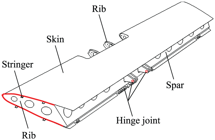
Aircraft wing component.
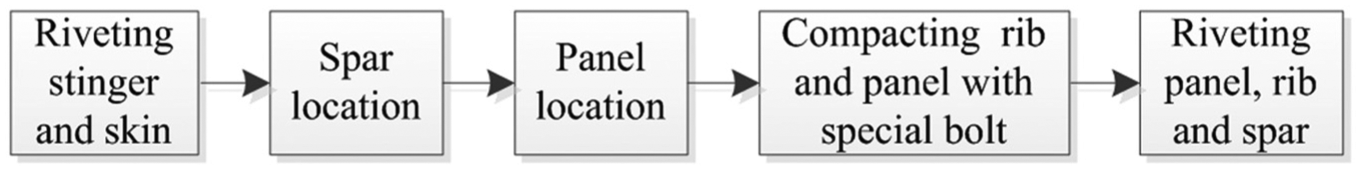
In general, to a get an accurate aerodynamic configuration of the wing, two kinds of assembly datum are used, which is the profile of skin and the profile of skeleton parts. When the profile of skin is taken as assembly datum, the cumulative direction of assembly error is from inside to outside, and the veracity is determined by the manufacturing accuracy of assembly jig and deformation in the assembling process. But, when the profile of skeleton parts is taken as assembly datum, the cumulative direction of assembly error is from inside to outside, and the veracity is determined by the manufacturing/assembly accuracy of skeleton parts. According to the wing structure and its assembly requirements, the assembly process is formulated (as shown in Figures 2 and 3).

Wing assembly process based on skeleton parts.
Wing assembly process based on profile of skin.
Positioning method based on contour boards
Traditionally, to locate the skin of wing component, a positioning method using contour boards is often adopted on rigid dedicated assembly tooling, as shown in Figure 4, where
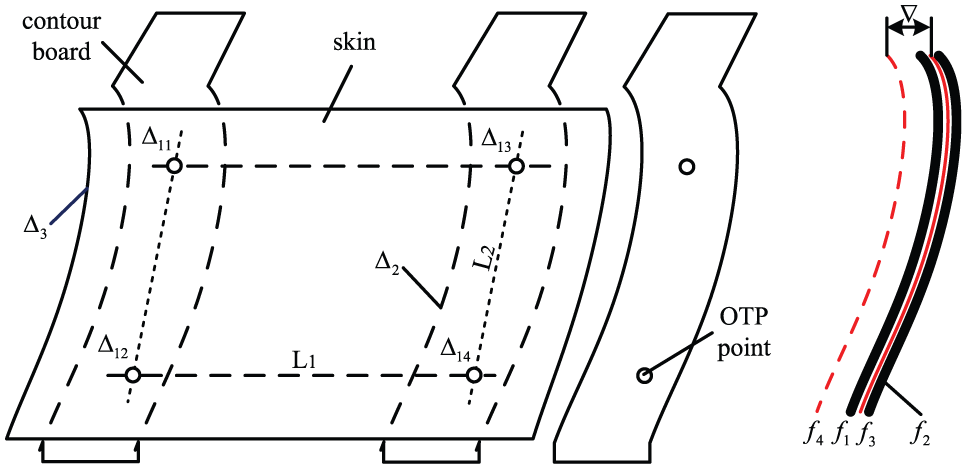
Positioning method based on contour boards.
In this positioning method, the profile of skin is chose as the assembly datum. Contour boards have a function of guarantying an accurate aerodynamic configuration of the skin. At the assembly process, the assembly error
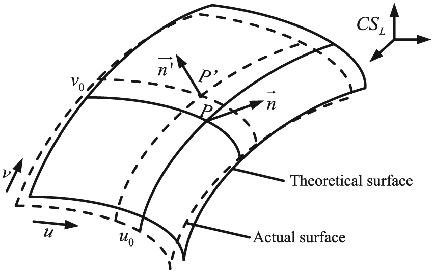
Assembly variation analysis on skin surface.
In Figure 5, the solid lines represent theoretical surface of skin, and the dashed lines represent actual surface when the wing at the assembly stage.

And the actual wing surface can be denoted as

Given P is a point on the theoretical surface with a parameter of
Assuming
Taking the variation of the manufacturing variation and the installing variation together, in the same way, we can calculate the variation of contour board, which can be denoted as
From above all, the assembly precision of wing skin can be calculated as

With the positioning method based on profile of skin, when the wing is jointed with the fuselage, the holes of hinge joints distribute on these two components usually cannot fit well with each other. Also, the gap and flush of skin usually cannot satisfy the accuracy requirement. The above phenomenon can be explained as follows:
When installing the contour boards to the assembly tooling, because there are certain angles in thecourse and spanwise direction between the wing and the horizontal datum plane of the whole aircraft, high positioning accuracy requirement would be needed to the mounting bracket that supporting the contour boards. So the configuration of contour boards is hard to guarantee. What is more, there are lots of contour boards in the rigid dedicated assembly tooling, and the straightness between the points at same height on the profile of contour boards is also hard to guarantee. The above factors would impact the aerodynamic configuration of the wing directly.
When assembling the wing component in actual, because the mating area between the skin and the contour boards takes up a lot of state, the assembly relationship is complex. To assemble the components to the desired accuracy, kinds of compensation method would be used, such as adding connecting interface and piece and so on, which making the assembling operation inefficiency.
The rib is located by special fixed stop in spanwise direction and by special mobile stop in course direction that mounting on the contour boards. Because stops are operated manually, lots of second locating phenomenon would appear when jointing ribs and spar together, which makes the assembling quality hard to ensure.
After assembling the parts together, profile of the wing is often detected by a straightedge ruler. Also, another special contour board with an amplified profile is often used to estimate assembly error. So we cannot get the exactly error under this kind of detecting method.
Flexible assembly method based on coordination holes
When the skeleton parts are taken as assembly datum, most often, the positioning method is also based on contour boards. Although the contour board has a profile of the skin, but only coupled with a lot of shims which have a thickness of wing skin, the contour board can be used to locate the rib and other skeleton parts. The above assembly method is similar to the assembly process based on profile of skin. Inevitably, the problems mentioned in chapter 3 would occur.
Under the digital assembly environment, it is easier to ensure the position of holes; also, the distance and the concentricity of two holes can be guaranteed at a high precision. And the mate of two holes has a simple assembly relationship compared with the positioning method based on the profile of contour board. To improve the low assembly accuracy and avoid the assembly problems mentioned in section “Positioning method based on contour boards” with contour boards, a positioning method based on coordination holes is proposed. Coordination holes appear in couples, which have the same dimension and position in the aircraft part and its corresponding locator. So to the wing rib, it is need to add two new holes on the web plan (as shown in Figure 6). A special locator which is used to locate the rib is designed. The locator is a plate with a shape of  . The front area of the two flanks of the plate is used for locating the web of ribs, which has two coordination holes. The holes are located on one line that is perpendicular to the symmetry axis of the plate. The two holes have a relationship with the two holes that are designed on each rib. The three installing holes distribute as a triangular, which are used as measuring the position of the locator with a laser tracker, and also are used to locate at the front area of the plate. It is mentioned that the coordination holes can also be used as optical target points (OTPs) as locating the rib.
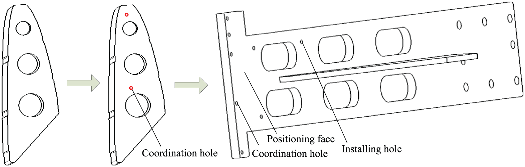
Positioning method based on coordination holes.
During the locating process using coordination holes, when the skeleton parts are positioned on the assembly tooling, the axes of the coordination holes will not coincide with each other because of the existence of the manufacturing error of the parts and the installing error of the locator. The mating error between the locator and the rib that caused by the coordination holes can be calculated by the following three steps.
Step 1: calculate the mating error which is caused by the position of coordination holes
Without considering the error at the direction that perpendicular to the positioning face, assume that the position error of coordination holes on the rib is

Step 2: calculate the mating error which is caused by the diameter and its error of coordination holes
Assume that the diameter and its manufacturing error of coordination hole on the rib are

As shown in Figure 7, the mating error which is caused by the diameter of coordination holes can be calculated as
where
Positioning method based on coordination holes.
Step 3: calculate the comprehensive error of coordination holes
The comprehensive error of coordination holes has a relationship with the error of position and dimension, which is composed of two kinds of error, and it can be calculated as

When assembling the rib using coordination hole, the profile of wing skin is more concerned. Supposing that the two coordination holes have two mating errors
Coordination error of the rib and the locator.
In Figure 8, A is the typical reference point that distributes on the profile of the rib,
Supposing that the profile of rib has a manufacturing error of

Experimental verification
Description of the object
There are four wing flap components in a certain aircraft, that is, the inboard, the outboard component and their exactly symmetrical other two components (as shown in Figure 9). Forty-six ribs are included in the four components except for the four end ribs. On the macroscopic, the position and the amount of the ribs distributing on the spar are different from the inner one and the outer one, and the length of the two products differs from about 300 mm. We can know the components have a complex structure, and they need inside and outside assembly operations, making it hard to ensure the assembly accuracy. Besides, high assembly accuracy of the profile between components is required, which locating at the interface of the 14th rib and 15th rib.
Structure of wing flap component.
Assembly precision based on contour boards
In Figure 4, when adjusting the jig to the desired accuracy with a laser tracker, the two OTPs that locating on the end of counter board are taken as installing datum. Where L1 is the distance between two adjacent counter boards, L2 is the distance between the two OTP points. When computing the assembly error between skin and its positioning tooling, the composed error of in practical production are as follows:
Based on the error mentioned before, the coordination error between counter board and skin at two adjacent counter boards can be calculated as

By applying probability statistics, the result is shown as

After measuring the accuracy on the inspection table at the top, the center, the rear area of the product with a laser tracker, the measured coordination error ∇1 between skin and ribs at the typical reference point A in Figure 8 is shown in Table 1.
Skin assembly precision based on contour boards (mm).
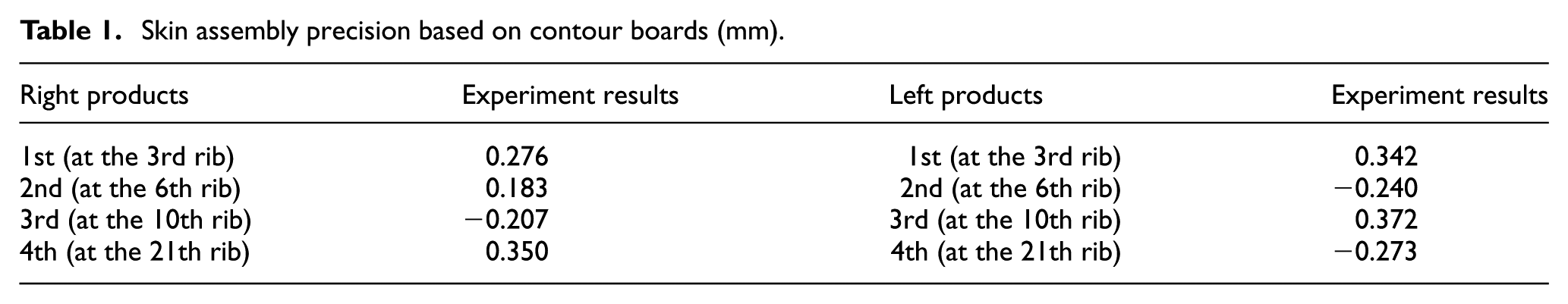
From the detecting results, we can see that the assembly accuracy range of the skin is (−0.273, +0.350) mm, the average value is 0.28 mm, which can fit the design requirement well. From the above information, we can see that the result is roughly in accordance with the theory analysis and showing that the presented algorithm is valid.
Assembly precision based on coordination holes
Structure of the locating unit
With the idea of DA approach, dealing with the characteristics of flexible tooling and assemble datum chosen before, one typical locating unit is designed to position all of the 46 ribs (as shown in Figure 10). The locating unit has three motion axes. Each motion axis is composed of the precision ball screw assemblies and the ball rail systems, the raster rule and the limiting switch and so on. As the locating unit working, the end-locater is controlled to move by the servo motor to any locating position during the effective stroke, making the locating position adjustable along X/Y/Z axis. To enhance the working stability, the motor has a function of band-type braking, and the pneumatic clamping elements are worked with the ball rail system.
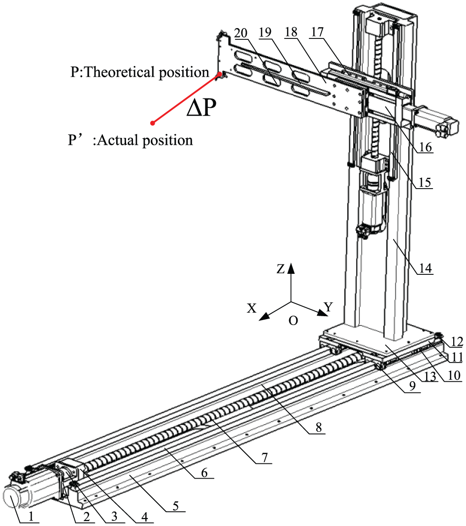
Structure of the locating unit.
To locate all of the 46 ribs above except the ending ones by the special locator using coordination holes, five coordination holes that distribute on the front area of the two flanks of the plate are designed. These five holes are divided into four groups by combining the bottom hole with other four holes, and they have a coordination relationship with the two coordination holes that are designed on each rib.
To verify the locating ability that used for locating all 46 ribs of four components, a simulation process is done under DELMIA (digital enterprise lean manufacturing interactive application) virtual environment (as shown in Figure 11). The first group of the coordination holes distributing on the locator is used for locating the ribs from the 2nd to the 5th, the second group is used for locating the ribs from the 6th to the 9th, the third group is used for locating the ribs from the 10th to the 21th and the fourth group is used for locating the ribs from the 21th to the 23th.
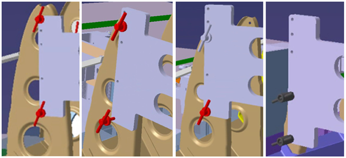
Different ribs with the same locator.
Positioning accuracy of the locating unit
The positioning error of the locating unit refers to the deviation of the actual position and the ideal position of the coordination hole in the reference frame of the tooling built. To get a high precision in the flexible assembly process, a lot of factors should be considered. The positioning accuracy of the coordination holes distributing on the locating unit determinates the assembly precision directly.
When assembling a product, the locator is controlled to move along three perpendicular directions with a predetermined value from the original point defined at each motion axis, and there is no external load at the process of debugging the locating unit. An accuracy of 0.05 mm is to be guaranteed according to design requirement. But the error of manufacturing, installation, measuring method, control system and so on can influence the positioning accuracy. Among these factors, the geometric accuracy of the locating unit is the most influential. Considering there is a process interface between the locator and the locating unit, the locator can be adjusted to a high installing accuracy. Mentioning that the locator is a rigid body, it has a tight connection with the locating unit; only one coordination hole is taken as the measuring point to represent the whole locator’s position. And the bottom hole is chosen as measuring datum.
At the positioning process of the unit, the positioning accuracy guarantee scheme is shown in Figure 12, which contains five steps:
Step 1: measure the theoretical position of the reference point P in the tooling coordinate system in CATIA software and then we get a coordinate value
Step 2: measure the position of the reference point P 10 times using a laser tracker at the original point of the X/Y/Z motion axis in the tooling coordinate system under the actual assembly environment. Then take the average and we get a coordinate value
Step 3: calculate the difference between
Step 4: following with the original moving value, the locating unit to is driven from the original point of the X/Y/Z axis to the desired locating position. After measuring the position of the reference point P using a laser tracker, observe whether it meet the requirement of positioning accuracy. If it does not meet the requirement, calculate the positioning errorΔP between the theoretical position and actual position at the reference point P on the locator, where
Step 5: put
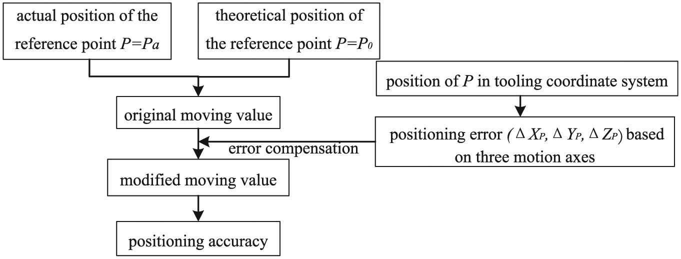
Positioning accuracy guarantee scheme for the locating unit.
Assembly accuracy based on the coordination holes
To verify the assembly precision based on coordination holes, the flexible assembly experiment can be carried out by the following four steps:
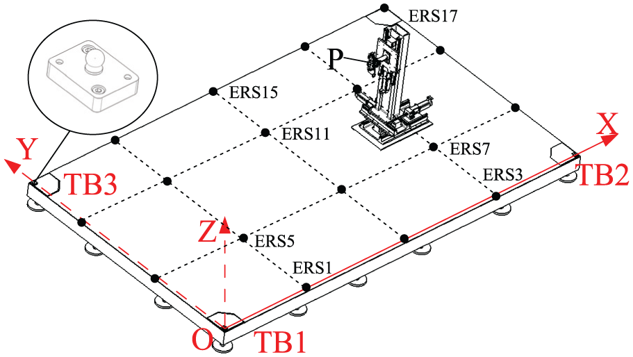
Step 1: establishing coordinate system of the tooling. Input the mathematical model of the components in the laser tracking measurement system, and take the three target measuring points TB1, TB2 and TB3 that distributing on the corner of the base frame plane to establish the Cartesian coordinate system of the tooling. To establish the coordinate system accurately, some ERS (enhanced reference system) points are often used (as shown in Figure 13). The coordinate of three TB points is shown in Figure 14.
Step 2: installing the locator on the locating unit. Follow the positioning accuracy guarantee scheme as shown in Figure 12 and then adjust the locator to desired position of the rib to be assembled.
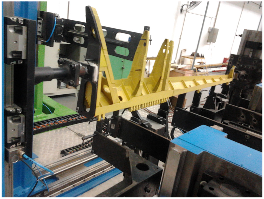
Step 3: assembling the ribs. Put one rib on the spar which has been positioned accurately before, fit the web of rib with the positioning face on the locator and then coincide two coordination holes that distributing on the rib and the locator with two pins, as shown in Figure 15. After checking the resilience of the pins, clamp the web of the rib and the flank of the locator with special tooling. Then the connecting holes can be drilled to rivet the rib and the spar together. And the assembling sequence of exiting ribs is from center to outside.
Step 4: assembling the skin. After assembling the four stringers, cover the skin on the skeleton parts, align the skin and the locator of the ending ribs, clamp them with special tooling, drill connecting holes and rivet them together.
Coordinate system of the tooling.
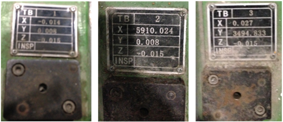
Coordinate of the three TB points.
Rib assembling process.
After the wing flap is assembled, remove the clamping tooling and the pins, take the assembled product off the tooling along Z direction and manipulate the control system to return to their original position. During the practical flexible assembling process based on the coordination holes, the composed error is shown in Table 2.
Error in flexible assembling process (mm).

According to the equations in chapter 4, by applying probability statistics, the theory assembly errors of skin among different rib series are shown in Table 3.
Assembly precision of the skin based on theory calculations (mm).
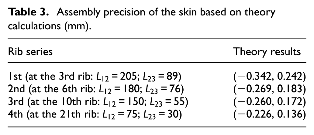
From the calculated results in Table 3, we can get that the semi-bandwidth of tolerance zone at the typical reference point A is 0.292 mm, which is sufficient to the assembly design requirements. To verify the presented algorithm is valid, we measured the component on inspection table at the top, the center, the rear area of the skin with a laser tracker. The accuracy of aerodynamic configuration can be shown in Figure 16.
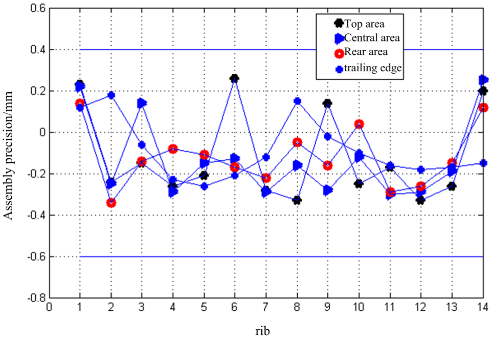
Assembly accuracy of the skin at different ribs of a component.
Also, the measured coordination error
Assembly precision of the skin based on coordination holes (mm).
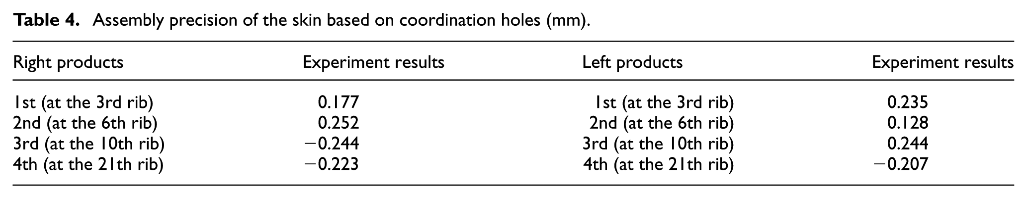
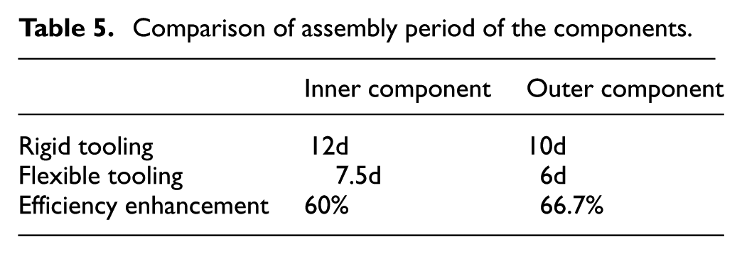
From the detecting results, we can see that the assembly accuracy range of the skin is (−0.36, +0.25) mm, the average value is 0.21 mm, which can highly meet the accuracy requirements of this aircraft. Contrast with the assembly accuracy based on contour boards, we can know the precision has an improvement of 24%. What is more, statistics results showed that assembly period is 7.5 days comparing with 12 days using rigid dedicate assembly tooling; and the corresponding productivity is increased by 60%, as shown in Table 5. After the component is jointed with the wing box, the hinge joints rotate agile, and the measured results of the gap and flush between the two components can satisfy the accuracy requirement.
Comparison of assembly period of the components.
Conclusion and discussion
Only by measuring the OTP points distributing on the locator, we can know its actual position in the coordinate system. After adjusting the locator to its theory coordinate data, fix it on the locating unit, and the installing work can be finished. We can also fix the plate of the locator only one time in place on the locating unit without changing the locator. Then 46 ribs of the four components with different shapes, dimensions, and positions can be assembled, which is a reflection of high flexibility.
With a brief structure of the locating unit, more operating space for workers is available, and the detecting work is convenient. What is more, due to the compensating function of the locating error, the checking-up work for rigid assembly tooling can be reduced. And the locating error caused by the factor of abrading in rigid jig can be eliminated. Accordingly, the assembly accuracy of wing components can be more precise.
As assembling the ribs, a locating method of “one-plane-two-hole” is used. According to the “3-2-1” locating principle, the positioning face limits 3 degrees of freedom of the rib, and two mating coordination holes limit other 3 degrees of freedom. When the locating unit is controlled to position of the rib that needed to be assembled, the web of the rib is reclined on the flank area of the locator after it is put on the spar. Then we can put two pins through the coordination holes that are distributed on locator and rib. When the resilience of the two pins fitting the design requirement, we can clamp up the locator and the rib. And experiment results show that the assembly error of rib profile is about 0.15 mm, which is sufficient to assembly work. If it does not fit the design requirement, we can easily find out the assembly problems using the above method, such as the inappropriate tolerance allowance between rib and spar, the angle of flange or the flatness of rib web does not fit the design requirement, the position relationship between coordination hole and rib profile does not satisfy the designed tolerance and so on. And then some repairing work would be done on the mating plane of rib and spar. This is considered as the most convenient of this positioning method compared with assembling the ribs using contour boards.
Experiment results showed that the flexible assembly system can work with the required locating precision of tooling and the assembly precision of products within the aerospace industry, and the corresponding productivity is increased. Although the assembly process is easy to complete, but in the actual assembly work, it has a high accuracy requirement for the part’s manufacturing accuracy with the positioning method of “one-plane-two-hole.” This can cause a long assembly period by repairing wing components and its locators to meet the resilience requirement of pin. How to balance the manufacturing accuracy and the assembly accuracy requirement is to be further explored. Besides, the error caused by assembly deformation has a great influence on assembly accuracy. Principals of the emerging of the assembly deformation are to be researched, how the deformation delivers and how to control assembly deformation are the focus of the next research work.
Footnotes
Declaration of conflicting interests
The author(s) declared no potential conflicts of interest with respect to the research, authorship and/or publication of this article.
Funding
The author(s) disclosed receipt of the following financial support for the research, authorship, and/or publication of this article: The authors would like to thank the National Natural Science Foundation of China (Grant No. 51375396).