
Abstract
One of the primary processes for the production of composite parts is the liquid composite molding process. This process is based on the injection of resin into a mold, which is usually metallic. Today, studies are being undertaken to produce these molds using Hextool™, a carbon fiber–reinforced thermosetting plastic. The molds, constructed by draping prepregs, must be finished by free-form machining to ensure the dimensional and surface quality requirements. An arithmetic roughness of 0.8 µm is required, and this quality is not attained by milling operations. Thus, a manual polishing operation is necessary. However, to minimize the time taken by this manual operation, it is necessary to verify the roughness obtained by milling. Thus, the work presented in this article consists first of a study of the capability of milling to produce molds from Hextool with given surface quality requirements. The conclusion of this study is to define values of radial depth of cut to attain a surface quality with minimum machining time. Second, this work highlights how to replace the manual polishing operation by a machining operation with an abrasive diamond tool. Thus, the capability of an abrasive diamond tool to machine a mold with high surface requirements is discussed.
Introduction
Molds manufacturing is a complex operation which is studied in several research works.1,2 However, few works concern the machining of fiber-reinforced composite molds. In case of metallic molds, machining procedure plan is generally composed of milling and polishing operations. To decrease the complexity and cost of the polishing operations, the roughness attempted by the finish milling operation has to be controlled. 2 The goal of this article is to develop a manufacturing process for fiber-reinforced composite molds.
Moreover, free-form machining of fiber-reinforced composite materials is not as controlled as metal free-form machining. The machining of fiber-reinforced composites is fundamentally different from the machining of metal from many points of view.3,4 In fact, cutting forces5,6 and surface roughness depend on fiber orientations. 7 Furthermore, the cutting of such materials can lead to many problems, such as peeling of fibers or pullout, 5 with fast tool wear. 8 In general case, the study of composite materials machining concerns the modeling of the cutting forces or cutting condition in order to avoid delamination and to control material integrity after machining.4,5,9
The originality of this article is to study the behavior of a heterogeneous fiber-reinforced composite material during free-form machining to control the machining roughness. The aim is to conclude on the contribution of the materials and cutting process on the final machining surface roughness. Moreover, this article studies the roughness benefit of a grinding operation performed on computer numerical control (CNC) machines for fiber-reinforced composite material. This study is illustrated on Hextool™; however, results can be extended to the free-form machining of other composite materials.
The presented work is a part of the general problematic around the achievement of low surface roughness during the free-form surface machining of composite materials. The modeling methods are based on experimental procedures. The results could be transposed to other composite materials and applications. Indeed, the use of an abrasive tool developed here seems to be relevant when a low level of roughness is required in a composite material part.
In the first section, the Hextool material and mold process plan is introduced before a geometrical study of the theoretical pattern left by ball-end cutting tool on the machined surface is presented. Then, experimental tests are performed to highlight a minimum attainable roughness value using polycrystalline diamond (PCD) cutting tools. The best surface quality–productivity ratio is achieved when the minimum attainable value appears. Finally, the feasibility of finishing a mold with an abrasive diamond tool, using five-axis machine tools, is discussed. The micro-grain metal-bonded diamond tool used is presented. Then, with respect to roughness and cutting force results, the capability of this mold finishing process is studied.
Materials and machining process
One of the primary processes for aeronautical structure parts made from the composite materials is the liquid composite molding (LCM) process. LCM is based on injecting resin into a closed mold containing a dry fiber preform. The LCM process allows complex parts to be manufactured with an excellent geometric and structural quality compared to traditional prepreg-autoclave processes. 10
Hexcel Composites Company proposes a new carbon fiber–reinforced thermosetting plastic named Hextool. This material is designed to replace the metallic molds used in the LCM process. Indeed, the major advantages of using Hextool for molds are its thermo-elastic behavior close to that of composite molded parts and its cost compared to Invar®.
The manufacturing of Hextool molds requires a finishing operation using free-form milling to obtain an arithmetic roughness of Ra = 0.8 µm. This value is considered to be necessary to limit wear and for the cleaning of the mold after the LCM process. In this section, Hextool is first presented after the presentation of mold in Hextool machining process.
Material presentation
Hextool M61 is a 2000-g/m2 carbon fiber–reinforced mat consisted of 8 × 50-mm prepreg bundles presenting a quasi-isotropic orientation (Figure 1). The volume of high-strength carbon fiber is 60% and that of bismaleimide resin is 38% (by weight). The mechanical properties are presented in Table 1.
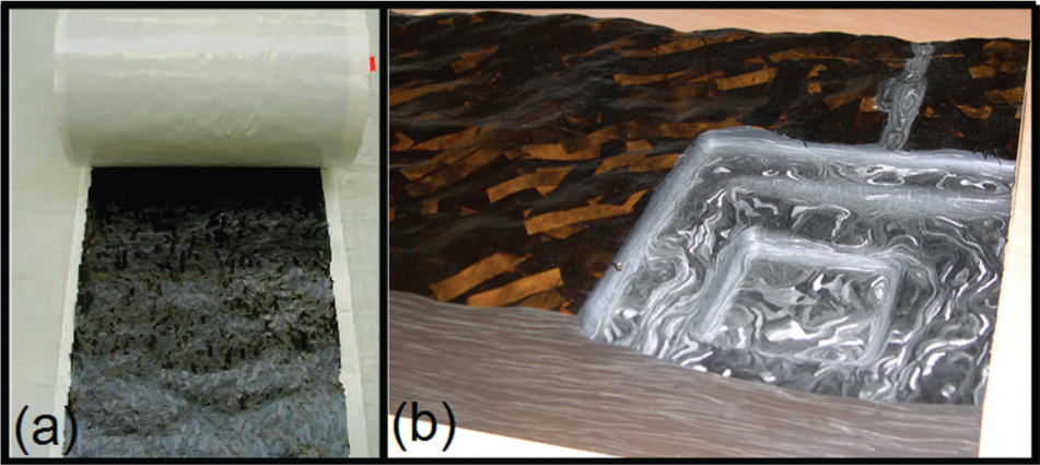
(a) Hextool™ in prepreg and (b) Hextool after processing.
Mechanical properties of cured Hextool™ M61.
DMA: dynamic mechanical analysis.
Hextool can be used as mold for LCM processes. Usually, the manufacturing process of mold in Hextool is as follows:
Lay-up prepregs on a master mold;
Cure in autoclave;
Milling operation for semi-finishing and finishing to remove excess material (around 5 mm) and to reach the dimension requirements;
Manual polishing operation to conform to the surface roughness requirements. An arithmetic roughness of 0.8 µm is expected to strip the mold parts and to avoid clogging of the mold surface;
Treatment of the mold with sealer and release agent.
Machining process
For LCM process, molds have to propose an arithmetic roughness of Ra = 0.8 µm. A previous study showed that surface quality requirements cannot be attained simply by milling with carbide or PCD tools. 11 Thus, today, a manual polishing operation is performed. This operation can be reduced if the roughness obtained by milling is controlled. 2 To increase greatly the productivity of such molds, the study presented in this article focuses not only on milling quality control but also on the automation of the finishing of fiber-reinforced composite material molds using a CNC machine tool. Thus, a global automated fiber-reinforced composite material mold manufacturing process that respects surface quality and productivity requirements can be proposed.
The first part of the study concerns the finishing milling operation for Hextool molds using a PCD cutting ball-end cutting tool. The influence of the radial depth of cut is analyzed with regard to an expected Ra, in order to minimize the machining time. This study highlights the particular behavior of the composite material–tool couple, which leads to a minimum attainable Ra value. In our case, this value is greater than 0.8 µm. A supplementary CNC finishing operation must, therefore, be studied.
The automation of polishing has many advantages, and the literature provides various automated experiments for metallic molds. For metal polishing, anthropomorphic robots, 12 parallel robots 13 and three or five-axis CNC milling machines 14 can be used. Polishing paths should be multidirectional, 15 and the control of polishing forces is a critical parameter of the process. Concerning the grinding of carbon fiber–reinforced plastics, some studies show that a low surface roughness can be obtained. 16 Furthermore, the control of grinding forces is not necessary, and tool paths could be similar to usual milling tool paths. Thus, the grinding process seems to be easier to perform on CNC machines than the polishing process. However, specific grinding wheels need to be designed with respect to the materials and mold shape. Thus, a second study is conducted in order to examine the feasibility of a finishing process using an abrasive diamond tool on five-axis machine tools and to highlight the impact of grinding process on surface roughness.
One of the principal requirements for mold surfaces concerns the roughness: Ra = 0.8 µm. Such a criterion is generally used in the literature and in industry, even if Ra is not well adapted for composite materials. 17 However, the surface quality obtained after the milling operation is due to two main behaviors: first one comes from the behavior of material during the machining process and the second one from the pattern left by tool shape and geometrical cutting condition. In the next section, the theoretical pattern left by the tool on the mold is studied.
Geometrical roughness study
In order to control the roughness achieved by milling with a ball-end cutting tool, a geometrical study of the pattern left by the tool on a plan surface is first carried out. The proposed model is validated on an aluminum part. This validation verifies that the influence of the machine cell used on roughness quality can be neglected.
Geometrical study
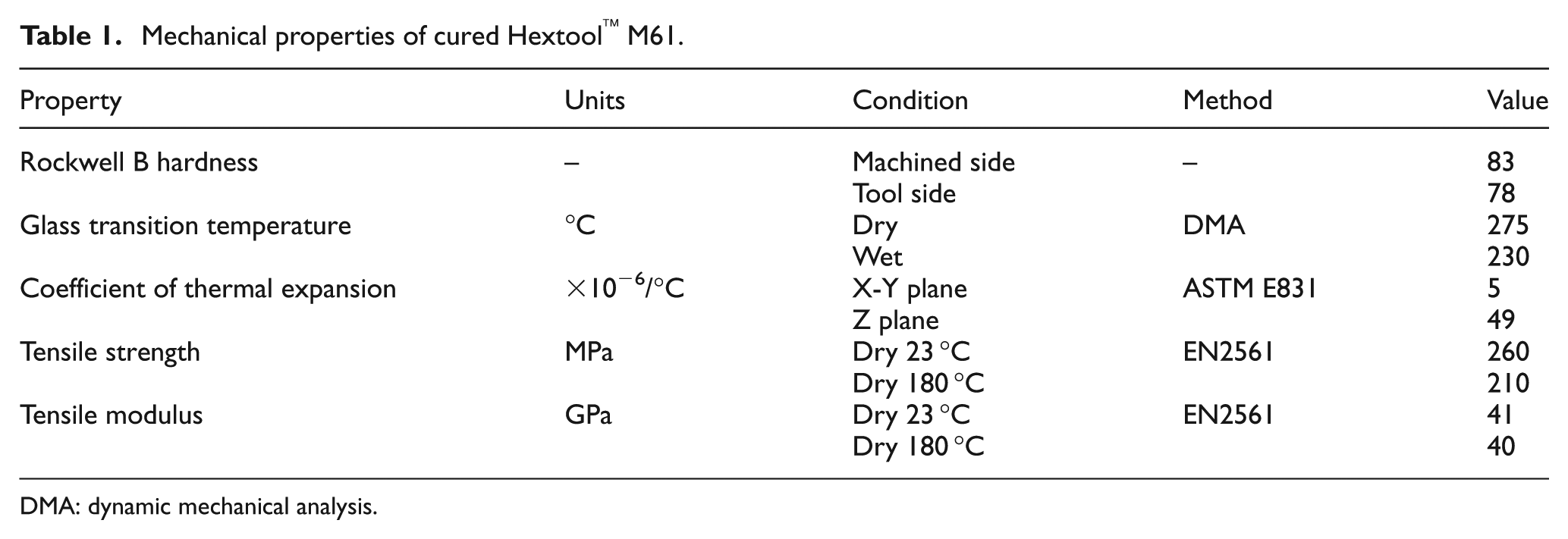
The prediction of the pattern left by the ball-end cutting tool is necessary to study the surface finishing process with various tool technologies. 18 Finishing by sweeping a ball-end cutting tool induces a particular pattern (Figure 2) on the machined surface due to adjacent tool paths 20 and feed per tooth. 19 However, this study concerns the estimation of the roughness computed perpendicularly to the feed rate direction for a machined plan.
For a plan surface, the theoretical scallop height hc is computed using equation (1) with Reff the effective cutting radius and ae the radial depth of cut (Figure 2(b)) 20

Thus, the theoretical arithmetic surface roughness Ra perpendicular to the feed rate direction is computed by equation (2) 21

In order to observe only the impact of radial depth of cut on roughness, feed per tooth fz remains several times smaller than the radial depth of cut ae. In this case, the conventional roughness model (perpendicular to feed rate direction) is in good agreement with the machined surface. 18
The theoretical scallop height and arithmetic roughness are both expressed with respect to the effective cutting radius Reff. In the case of a ball-end mill, Reff is equal to the radius of the tool.
When cutting a homogeneous metallic material, the machined surface pattern obtained is closer to the geometrical model than in the case of composite materials. 22 Thus, the decrease in radial depth of cut ae in the case of a metallic material leads to a decrease in arithmetic roughness Ra until the appearance of the minimum chip thickness phenomenon. 23 The machining and pattern measurement of metallic material parts guarantees that the machine cell has a negligible influence on surface roughness for the future machining condition.
Validation on an aluminum part
In order to validate the theoretical roughness model in our machining conditions and with a Huron KX15 machine tool, a test was carried out on a homogeneous metallic material, aluminum. A 10-mm-diameter carbide ball-end mill was used with a cutting speed of 500 m/min, a feed rate of 3200 mm/min, an axial depth of cut ae of 0.5 mm and a tilt angle θt of 5°.
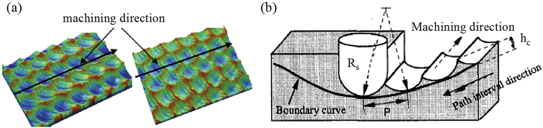
The roughness measurement will be performed with a rugosimeter Mitutoyo Roughness Surftest SV500 with a ∅5-µm probe. As the diameter of the probe can be neglected with regard to ae and the tool radius, the measure arithmetic roughness is closed to the real arithmetic roughness (Figure 3). In Figure 3, theoretical measured profile is computed from theoretical machined profile with the hypothesis that the measurement is realized without defect with a ∅5-µm probe.
Comparison of theoretical machined and measured profile.
Figure 4 shows a good correlation between the theoretical and the experimental arithmetic roughness. This result validates the analytical model of roughness for this range of radial depth of cut. However, a minimum attainable roughness value of 0.2 µm emerges. This phenomenon could be explained by tool vibration, 24 run out, minimum chip thickness 23 or cutter edge radius. 25 For the subsequent tests carried out on composite materials, we considered that phenomena related to the machine cell could be neglected. For composite materials, the phenomena induced by machining are different, due to material heterogeneity. 26 Variations in radial depth of cut should highlight different kinds of behavior.
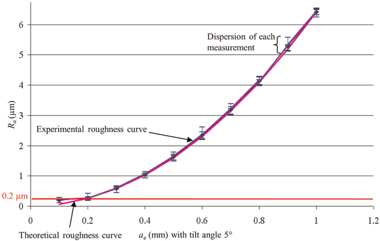
Theoretical arithmetic roughness compared with experimental roughness (aluminum).
Surface finish using PCD ball-end tools
The first step for machining Hextool molds is based on milling with ball-end tool. The aim of this milling operation is to remove a high volume of material in order to obtain the final part shape. To increase the global productivity of mold manufacturing, the final roughness obtained by milling has to be controlled.
An experimental procedure is then defined to study the influence of the radial depth of cut ae on surface roughness. Analysis of the results enables to define a minimum roughness value attainable in Hextool using a PCD tool.
Experimental procedure
In order to study the influence of radial depth of cut on roughness in Hextool, surfaces were finished by sweeping operations (Figure 2(b)). Ten areas of 10 × 50 mm were machined using a PCD ball-end cutting tool (diameter = 10 mm, Figure 5). PCD tools were used due to their better performance than carbide tools, in both milling operations 27 and turning operations. 28 Indeed, PCD tools generate a lower surface roughness and require lower cutting forces. In fact, a specific cutting pressure around 300 N/mm2 is obtained when milling Hextool with a carbide tool. This pressure is only 150 N/mm2 when a PCD tool is used. 14
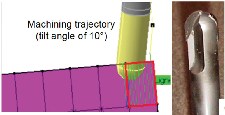
Machined part and tool paths with ball-end cutter.
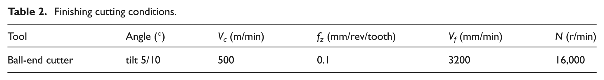
Different values of radial depth of cut were tested (Figure 6). Two tilt angles θt of 5° and 10° were used to avoid a null cutting speed. 29 These tests were carried out with a five-axis milling machine (Huron KX15), in dry conditions. Laminates were previously faced to obtain a cutting thickness equal to 0.5 mm. Cutting conditions, determined through previous tests, 11 are given in Table 2.
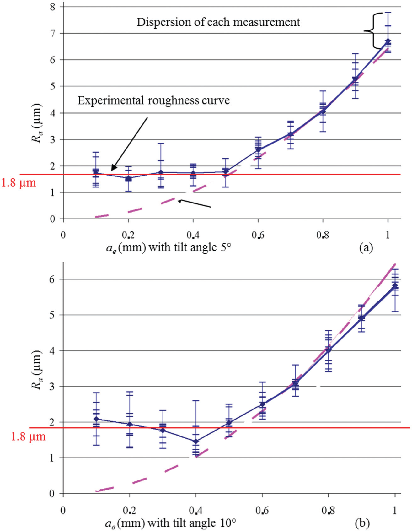
Theoretical arithmetic roughness compared with experimental roughness with PCD ball-end cutter with a tilt angle of (a) 5° and (b) 10°.
Finishing cutting conditions.
For each area, 10 measurements were performed perpendicularly to the feed rate direction. Measurement conditions and surface indicator settings are in agreement with ISO 4288.
Results and analysis
Figure 6 illustrates the measured roughness values according to the radial depth of cut for a PCD ball-end cutter. The dispersion on arithmetic roughness is about 1–2 µm. This high dispersion for Hextool can be explained by the heterogeneity of a composite material, which generates different behaviors during machining. Indeed, this behavior depends on diverse fiber and matrix properties, fiber orientation and the relative volumes of the matrix and fibers. 26
Figure 6 shows a good correlation between theoretical and experimental values for a radial depth of cut ae greater than 0.6 mm. For a radial depth of cut ae lower than 0.5 mm, the average arithmetic roughness is almost constant at around 1.8 µm.
This value is the minimum attainable roughness value for this PCD ball-end cutter tool–Hextool couple. Thus, a radial depth of cut below 0.5 mm does not reduce the roughness. This value of 0.5 mm enables a maximum surface quality to be achieved in a minimum machining time, for a Hextool–PCD ball-end cutter couple.
However, if the Hextool fiber diameter (
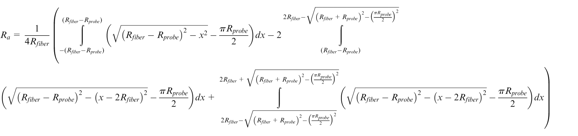
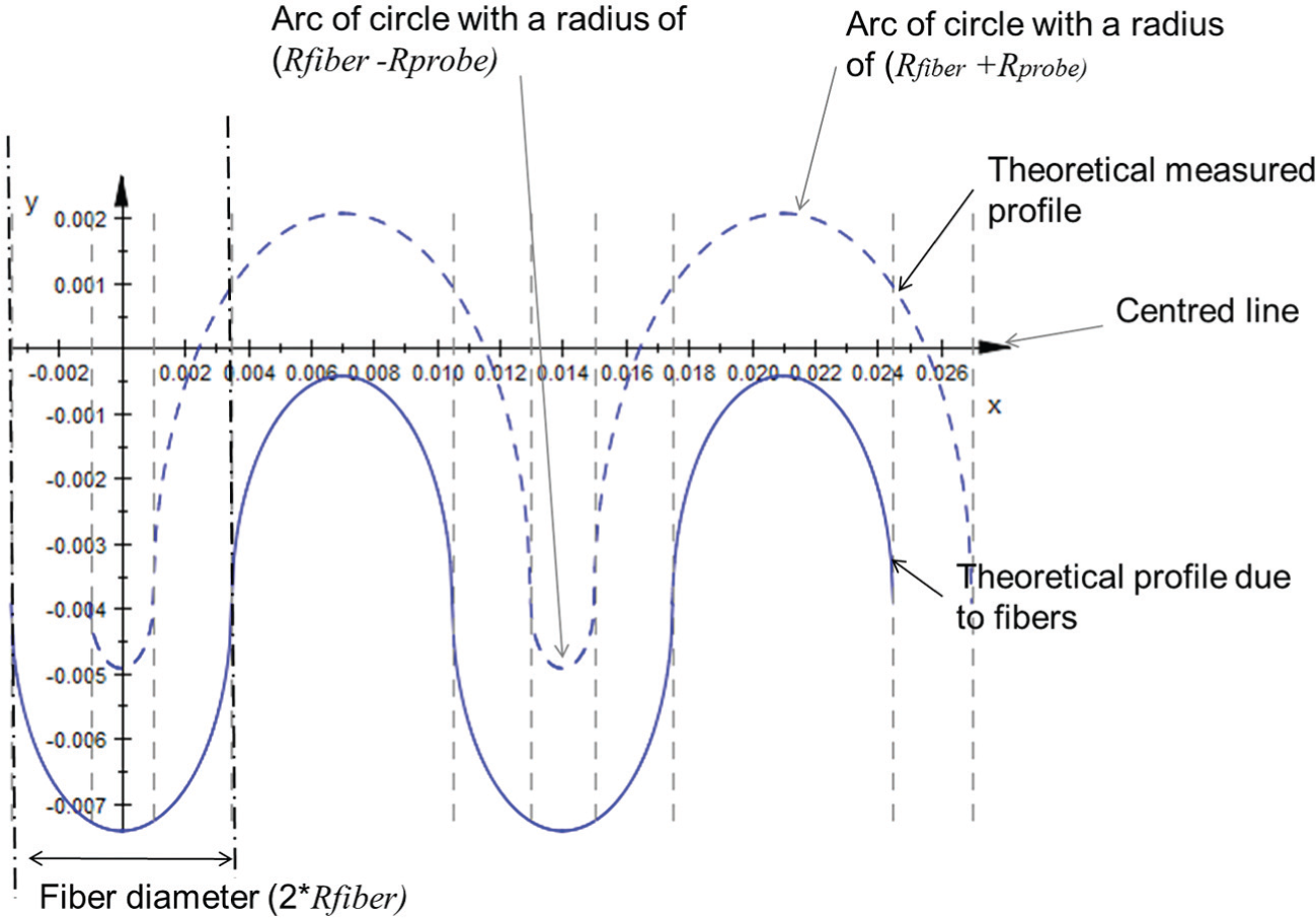
Theoretical and measured profiles due to fibers.
In this case, the arithmetic roughness computed from the theoretical measured profile due to fibers is equal to 1.86 µm. Thus, we can suggest that the minimum attainable roughness value is linked to the Hextool fiber diameter.
To validate our hypothesis, the cutting behavior which leads to this minimum attainable roughness value is analyzed with scanning electron microscopy (SEM) and profilometer images of the machined surfaces. Figure 8(a) and (c) shows the machined surface with a PCD ball-end cutter and a radial depth of cut of 0.1 mm; broken fibers and resin pullout appear. Thus, the surface quality produced is due to phenomena such as pullout during machining and the diameter of the fibers. These phenomena occurred during previous tests on Hextool 10 and also in the literature with other composite materials.26,30Figure 8(b) and (d) shows a surface machined with a radial depth of cut ae of 1 mm; broken fibers and resin pullout still appear. However, the pattern induced by the sweeping operation appears on the SEM images (Figure 8(d)). Thus, we can conclude that when the scallop height value is near to the pullout size, the minimum roughness value is reached. This result is very much dependent on the tool and cutting conditions used and also on the machined material (size and fiber rate).
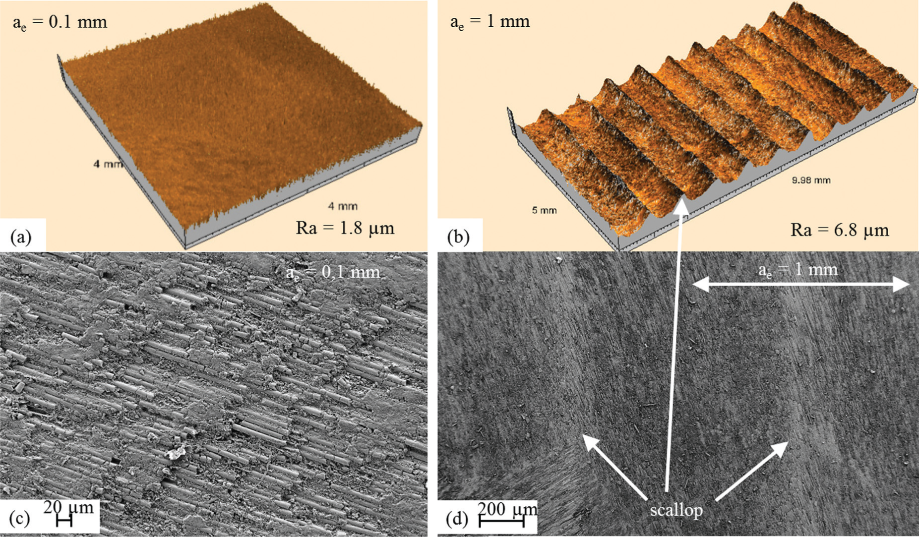
Profilometer and SEM images of machined surfaces with a PCD ball-end cutter and various ae: (a, c) 0.1 mm and (b, d) 1 mm.
This study highlights the appearance of a minimum attainable roughness value due to the pattern left by broken fibers during machining by sweeping over planes with a ball end. An optimal radial depth of cut value ae for these tool–material couples can be deduced from this experimental procedure. However, this value is higher than the projected quality requirements. Thus, in order to improve productivity, the next section deals with the automation of grinding using a CNC machine tool in order to replace the manual polishing operation.
Surface finish with abrasive tools
The definition of a mold grinding operation on a CNC machine tool must be conducted in two steps. The first step is based on the definition of an abrasive tool (tool shape and grit size choice) adapted to the mold shape and required roughness quality. The second step should ensure the correct choice of cutting parameters by analyzing their influences on productivity, grinding forces and tool wear. These two steps are discussed with an experimental view point.
In the following sections, the abrasive tool developed is first presented. An experimental test is then discussed to identify the grit size adapted to the required roughness and to conclude on the feasibility of the grinding operation on a CNC machine tool.
Abrasive tool
In order to perform the grinding operation on a CNC machine tool, a specific tool was developed in collaboration with Asahi Diamond Industrial Europe (Figure 9). This is a micro-grain metal-bonded diamond tool, made up of 75% diamond grit.
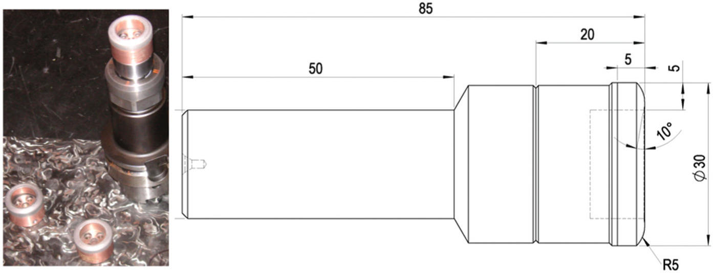
Abrasive tool with interchangeable heads.
The tool geometry is close to that of a toroidal mill. Indeed, this tool has to be used on a machine tool as a cutting tool, which makes the use of classical grinding wheel nonrelevant. Furthermore, the tool diameter is 30 mm. We estimated that this diameter is the higher diameter which is adapted to mold free-form grinding. Moreover, life time is proportional to the cutting diameter, for an abrasive tool. 30 Thus, the choice of diameter is a compromise between tool wear and tool accessibility.
Influence of grit size on roughness
Tests were performed with three abrasive tools having the same geometry but with three different grit sizes through the system of interchangeable abrasive heads. The grit size was about 25, 40 and 46 µm. In order to carry out these experiments, laminates were previously faced using a PCD end mill. The size of a laminate was 140 × 200 mm, and the arithmetic roughness measured was approximately 2 µm after milling. The tests were carried out on a five-axis milling machine (Huron KX15). A classic tool holder and cooling by soluble oil were used. After machining, roughness was measured using a Mitutoyo Roughness Surftest SV 500, with surface indicator settings in agreement with ISO 4288.
The chosen cutting speed was around 1080 m/min with a feed rate of 800 mm/min. Tilt and yaw angles were, respectively, equal to θn = 0° and θt = 1°. The axial and radial depths of cut were, respectively, close to 0.5 and 2.7 mm. The induced value of the theoretical scallop height and arithmetic roughness were then, respectively, equal to 1 and 0.27 µm. These values are lower than the functional requirements in order to evaluate the performance of the tool. Indeed, a low radial depth of cut value allows the analysis to focus on the influence of material behavior on roughness.
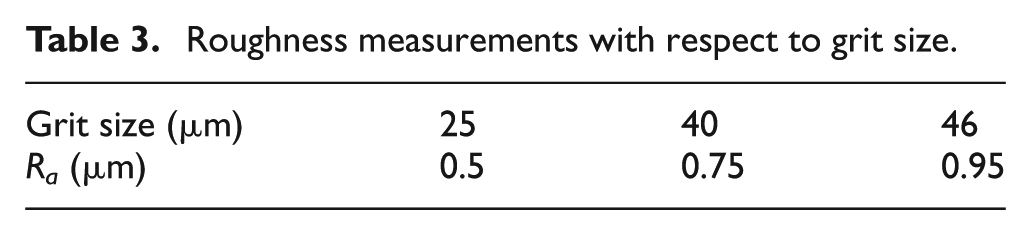
Table 3 presents the arithmetic roughness measurement in the machining direction and in the transversal direction for the three grit sizes. Note that average values of arithmetic roughness are identical in the two directions. We can note that a tool with a grit size of 40 µm enables us to obtain an arithmetic roughness of less than 0.8 µm on an average. However, we have to conduct more experimentation to guarantee this result despite tool wear and to link grit size with the value of the obtained arithmetic roughness.
Roughness measurements with respect to grit size.
Tool wear
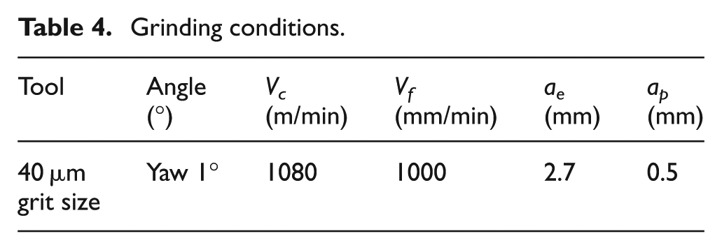
In order to study the wear behavior of the abrasive tool, surfaces of 140 × 208 mm were machined with the 40-µm grit abrasive head and with the grinding conditions given in Table 4. During these tests, form and roughness defect measurements were carried out. We can note that wear produces a tool profile modification during machining, which can lead to form defects on machined mold surfaces. Form defect measurements were carried out on the machined part with a probe (2-µm resolution) fixed to the spindle (Figure 10).
Grinding conditions.
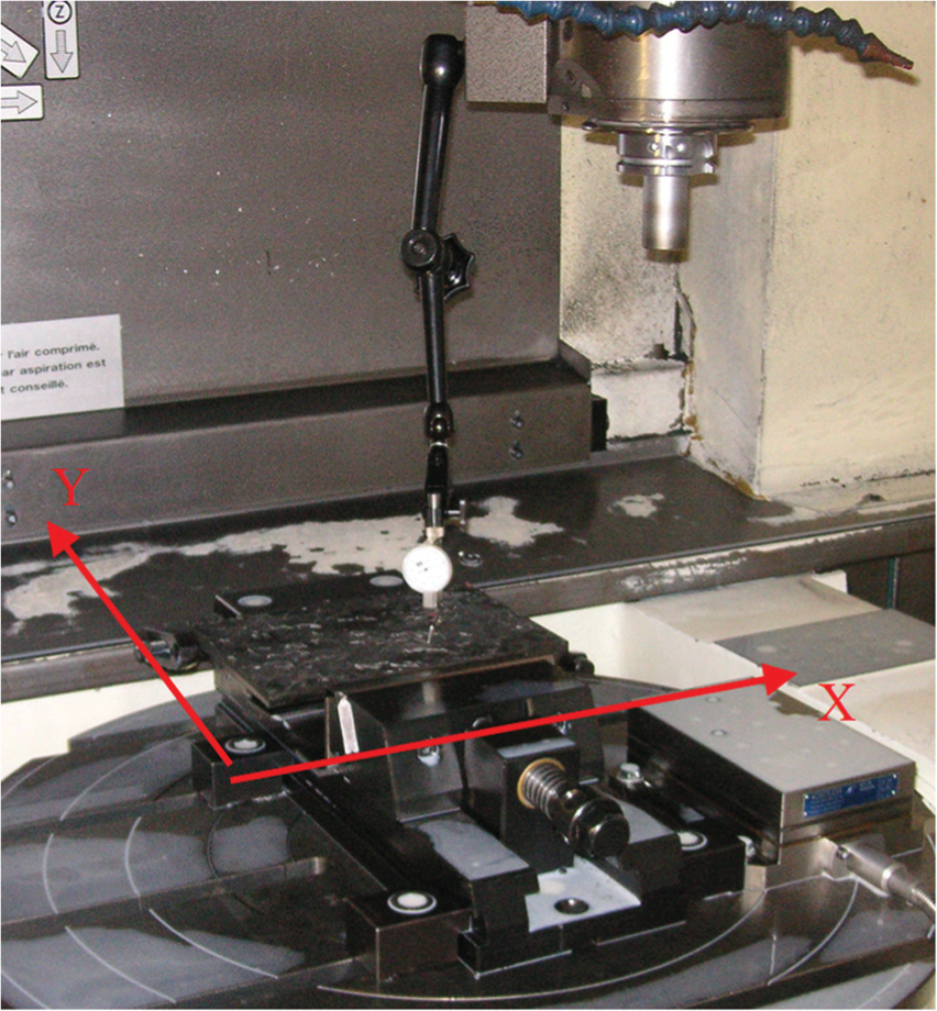
Form defect measurement.
Thus, only form defects induced by tool wear were measured. A defect along the direction perpendicular to the feed rate equal to 0.01 mm was measured when the tool had traveled 11 m. However, no form defect appeared in the sweeping direction. Thus, we can conclude that tool wear does not appear to be a real obstacle to the extensive use of an abrasive tool and simply needs to be taken into account during the tool path definition.
Figure 11 presents roughness measurements. We can note that tool wear has no influence on the surface quality; in fact, the roughness remains constant as the distance traveled by the tool increases. During these tests, 0.12 m2 were machined and a distance of 44 m was travelled. In fact, for an abrasive tool, wear does not necessarily have a negative impact on the roughness produced. 31
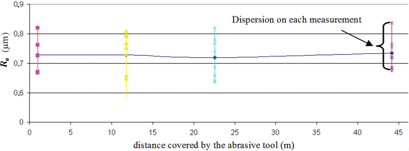
Roughness obtained with an abrasive tool of 40 µm grit size.
However, if Figure 11 is analyzed with respect to the goal of an arithmetic roughness of 0.8 µm, we can state that a tool with a grit size of 40 µm cannot guarantee an arithmetic roughness of less than 0.8 µm over the entire grinding surface. Indeed, some measured values of the arithmetic roughness are greater than 0.8 µm. From this observation, we can state that the use of a tool with a grit size of 25 µm is more relevant in our case study, even though a smaller grit size leads to a shorter tool life. The feasibility of grinding operations on CNC machines is next discussed by analyzing the results of experimentations with the 25-µm grit abrasive head.
Influence of cutting condition on roughness
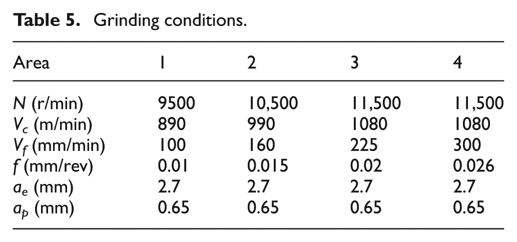
A series of tests was carried out to evaluate the feasibility of a grinding operation on a CNC machine and tool to determine cutting conditions. For this, four areas were machined with the 25-µm grit abrasive head under the conditions presented in Table 5 (Figure 12). The cutting speed and feed rate tested here were similar to classic values in grinding. In fact, a cutting speed of 1200 m/min and a feed rate of 200 mm/min were used by Hu and Zhang 16 and 2800 m/min and 360 mm/min, respectively, were used by Zhou and Xi. 32 The axial depth of cut was equal to 0.65 mm.
Grinding conditions.
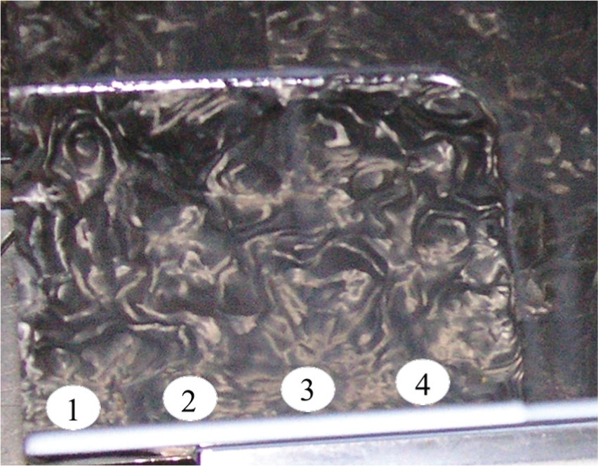
Part used for tests with areas 1–4.
The soluble oil used during this operation enables a grinding operation without loading the abrasive tool. For each area, the roughness measurements were performed in the machining direction and transversal direction. However, the average values of arithmetic roughness are identical in the two directions. This fact could be explained by the low value of radial depth of cut. In the following, only results for the transversal direction are presented. Furthermore, the dispersion on arithmetic roughness is about 0.1 µm for each area (Figure 13). This value is lower than for PCD finishing, and the phenomenon is principally due to the heterogeneity of the composite material and the random fiber orientation. 16
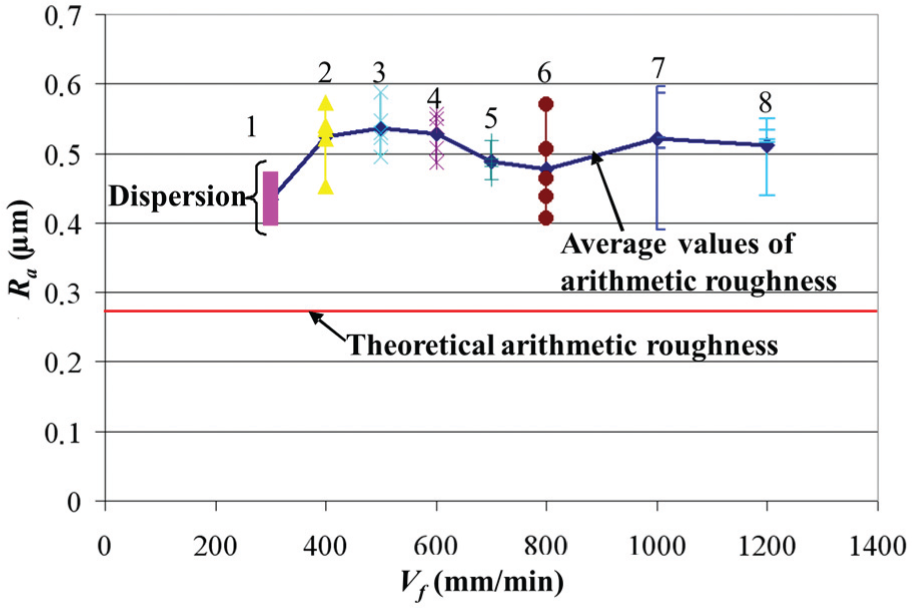
Roughness measurements in transversal direction.
Figure 13 shows that the cutting speed and the feed rate present a slight influence on the average arithmetic roughness. However, the tool was dressed with a whetstone between areas 2 and 3. This could explain the stabilization of the roughness for these areas. In fact, this operation cleans the tool and increases its abrasive power. After this experiment, we concluded that a cutting speed of 1080 m/min and a feed rate of 300 mm/min could be used as initial conditions.
Analysis of the roughness pattern
The gridding behavior, which leads to decrease in the roughness value, is analyzed with SEM and profilometer images (Figure 14). Figure 14 shows that pullouts are limited when abrasive tools are used. Indeed with the abrasive tool, fibers are not broken as in milling what ensures to improve the final roughness.
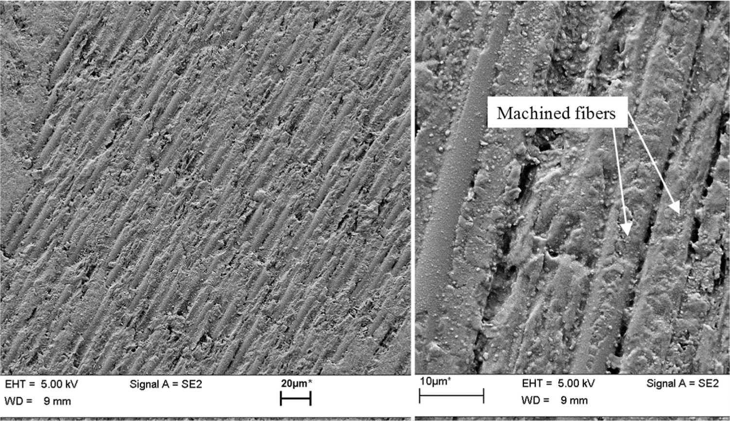
Surface machined with a 25-µm grit abrasive tool.
Results
The experimental tests carried out confirm that to produce a Hextool mold with an arithmetic roughness of less than 0.8 µm, a grinding tool with a grit size of 25 µm can be used on a CNC machine tool. However, work on the grinding tool should be continued in order to enable increased productivity, to control tool wear and fiber grinding phenomena. Moreover, the use of a grinding tool on a CNC machine tool requires working with a five-axis tool path and controlling geometrical defects induced by tool wear.
Conclusion
This study addresses the definition of finishing operations for molds made from composite materials, with a focus on the surface quality expectations. This work deals with both cutting and abrasive tool technology. The main conclusions are as follows:
The appearance of a minimum attainable roughness value due to broken fibers during machining by sweeping over planes with a ball end.
An abrasive tool can be used in order to reduce or even to eliminate the manual polishing operation.
An abrasive tool technology is proposed. The feasibility of a grinding operation on a Hextool mold using a CNC machine is demonstrated. Furthermore, this finishing operation enables an average arithmetic roughness of about 0.5 µm to be attained with the 25-µm grit abrasive head.
The presented work shows that the phenomenon that occurs during milling and grinding of composite material are not the same with regard to the fiber. The experimentations conducted in this work have attempted to initiate a model to predict the surface roughness during machining of composite materials.
Footnotes
Appendix 1
Acknowledgements
This work was carried out within the LCM-Smart Project (Hexcel, SKF Aerospace France, Issoire Aviation, ESI Group, Isojet, Visuol Technologies) supported by the French Ministry of Industry. This work was carried out within the Manufacturing 21 working group, which comprises 17 French research laboratories. The topics approached are as follows:
Modeling of the manufacturing process; Virtual machining; Emergence of new manufacturing methods.
The authors wish to thank Asahi Diamond Industrial Europe for this collaboration.
Declaration of conflicting interests
The author(s) declared no potential conflicts of interest with respect to the research, authorship and/or publication of this article.
Funding
The author(s) received no financial support for the research, authorship and/or publication of this article.