
Abstract
Carbon fiber–reinforced plastics have been widely applied in aerospace industry as aircraft structural components due to their excellent mechanical and physical properties. The countersinking process of the carbon fiber–reinforced plastic hole is indispensable for the assembly of countersunk head screw. In conventional countersinking process of carbon fiber–reinforced plastics, it is prone to produce the delamination, fiber pullout, poor surface levelness and dimensional accuracy of countersunk hole. As a new technology, the rotary ultrasonic elliptical machining for countersinking of carbon fiber–reinforced plastics is employed, which is a non-traditional process that can effectively improve the surface levelness, surface integrity and machining accuracy of carbon fiber–reinforced plastic countersunk hole. This article reported a feasibility study on the rotary ultrasonic elliptical machining for countersinking of carbon fiber–reinforced plastics without coolant for the first time. The processing principle of rotary ultrasonic elliptical machining for countersinking was illustrated according to the countersinking models and the equations of motion locus. Based on the principle analysis, the surface levelness, tool blades’ path and countersunk hole surface morphology in rotary ultrasonic elliptical machining of the separated and unseparated types were analyzed compared to that in conventional countersinking. In addition, the rotary ultrasonic elliptical vibration transducer was designed and fabricated, as well as the experimental platform was set up. The experimental results demonstrated that the rotary ultrasonic elliptical machining achieved much better results than that in conventional countersinking, such as lower thrust force, torque, cutting temperature, better surface levelness, hole dimensional accuracy, surface integrity and chip-removal effect. The experimental results also verified the feasibility of rotary ultrasonic elliptical machining for countersinking of carbon fiber–reinforced plastics.
Keywords
Introduction
Carbon fiber–reinforced plastics (CFRPs) are seen as an advanced material, which have been widely used in aerospace industry as aircraft structural components because of their excellent properties such as high specific strength, high specific modulus, corrosion resistance, wear resistance and low density. 1 For example, the usage of CFRPs in Boeing 787 and F35 strike fighter is 50% and 35% of structural weight for their main airframes, respectively.2,3
In order to assemble the CFRP skins and metal frames of aircraft, many assembly holes of CFRPs need to be machined. 4 As a conventional drilling method, drilling technology by twist drills is widely used to machine these holes. However, it is known to all that the drilling process of CFRP hole is difficult because of the specific properties of CFRPs such as anisotropic structure, abrasive nature and low thermal conductivity. 5 For example, primary defects produced in the drilling process include the delamination, exit spalling, burr, fiber pullout, fiber breakage and poor surface integrity of drilled CFRP hole as well as the rapid tool wear.5,6 For the sake of reducing the defects, different methods have been reported. On one hand, various tools consisting of twist drills, saw drills, step drills, candle stick drills, multifacet drills, core-special drills, dagger drills and diamond core drills are invented.7,8 On the other hand, ultrasonic vibration drilling process is also popularly applied.9–13
However, so far there have been no literatures reported about the machining of CFRPs countersunk hole in the skin surface of aircraft. For the purpose of finishing the assembly process between the CFRP skins and metal frames, the countersinking process of CFRP hole is mandatory for the machining of countersunk hole and the assembly of countersunk head screw.14,15 Meanwhile, the main defects are still generated in the conventional countersinking (CC) process of CFRPs, such as the delamination, fiber pullout, chips adhesion of hole surface, poor surface integrity and dimensional accuracy of countersunk hole, as well as poor surface levelness between the surface of CFRP workpiece and the surface of countersunk nail head.14,15 In particular, the poor surface levelness and dimensional accuracy of countersunk hole have negative influences on the aerodynamic smoothness and stealth performance of aircraft exterior surface, the perpendicularity of countersunk head screw after the assembly, the distributions of stress and load, the fatigue life of fastener hole, the strength of countersunk head screw as well as the connection strength between the CFRP skins and metal frames, as illustrated in detail in the published materials.14,15
The ultrasonic elliptical vibration cutting (UEVC) was first proposed by Shamoto and Moriwaki, 16 and the cutting principle and advantages of UEVC were reported in their studies. During the UEVC, owing to the elliptical nature of tool vibration being transferred to the cutting edge, the tool separated from the chip during each vibration cycle, which reduced the friction between the tool rake face and the chip significantly.13,16,17 In addition, the UEVC of the separated type brought many machining advantages, such as effectively reduced the cutting force,17,18 suppressed the burrs, 19 enhanced the machining accuracy, 20 increased the material removal volumes and improved the chip-removal effect, 13 as well as obtained superior surface finish and longer tool life. 21 Based on the above advantages, for the past few years, the UEVC technology had also been applied in drilling and milling processes.22,23
Therefore, in order to employ the advantages of UEVC, this article first introduced the rotary ultrasonic elliptical machining (RUEM) method for countersinking of CFRPs. RUEM is a non-traditional process that combines the rotary ultrasonic machining (RUM) and UEVC technology, which can effectively reduce the machined defects, as well as improve the surface integrity and machining accuracy of CFRP countersunk hole.
In this article, the feasibility study on the RUEM for countersinking of CFRPs without coolant is reported for the first time. It is divided into five sections. After this introduction section, that is, in section “Processing principle of RUEM for countersinking,” the processing principle of RUEM for countersinking is illustrated according to the countersinking models and equations of motion locus. Based on the processing principle, the tool blades’ path, the countersunk hole surface morphology and levelness in RUEM of the separated and unseparated types are analyzed compared to that in CC. Next, the rotary ultrasonic elliptical vibration transducer is designed and fabricated, as well as the experimental platform is set up in section “Experiments.” And then, the experimental results and discussions are presented in section “Experimental results and discussions.” Finally, the conclusions are drawn in section “Conclusion.”
Processing principle of RUEM for countersinking
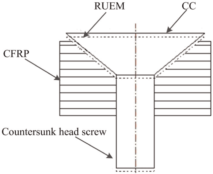
Figure 1 illustrates the schematic of RUEM for countersinking of CFRPs. Figure 2 shows the schematic of RUEM for the single polycrystalline diamond (PCD) blade of countersink cutter. As seen in Figures 1 and 2, w is the angular velocity of tool; a and b are the long and short radii (i.e. vibration amplitude) of the elliptical vibration locus, respectively;
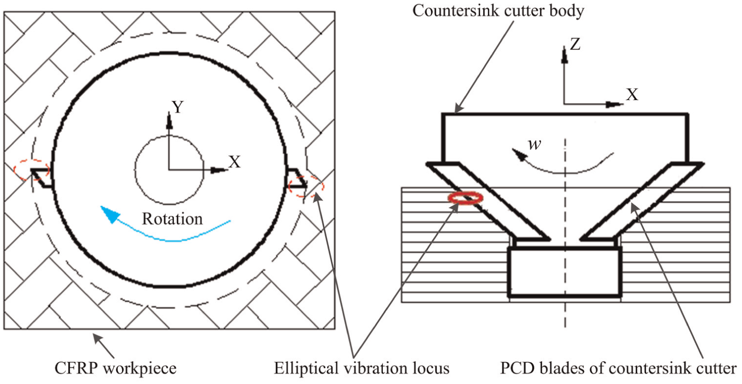
Schematic of RUEM for countersinking of CFRPs.
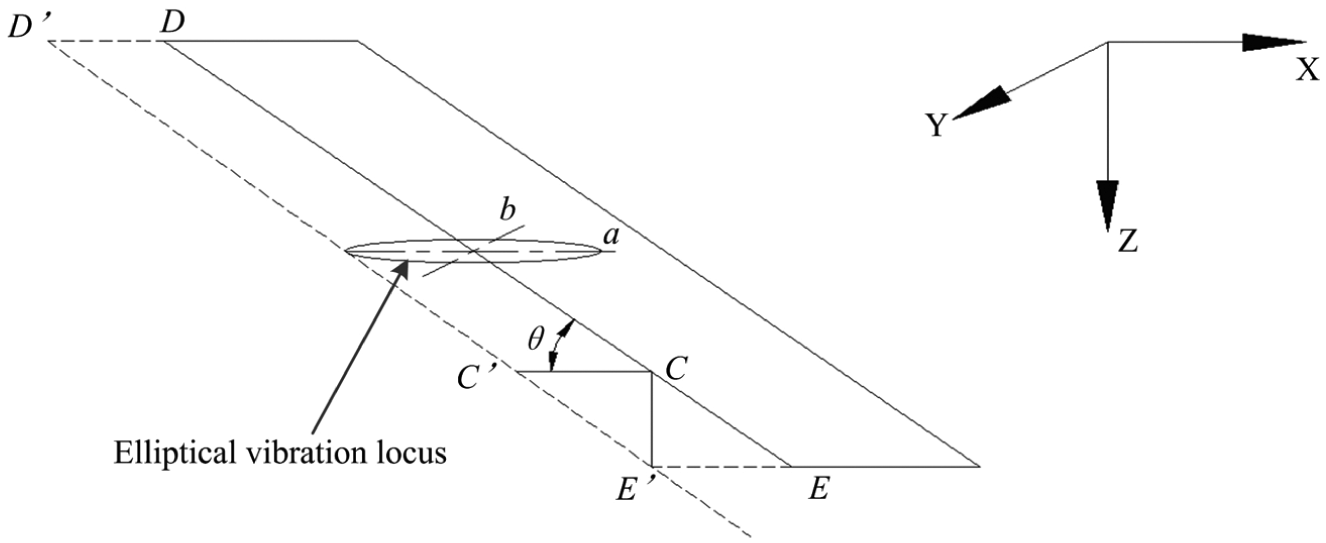
Schematic of RUEM for the single PCD blade of countersink cutter.
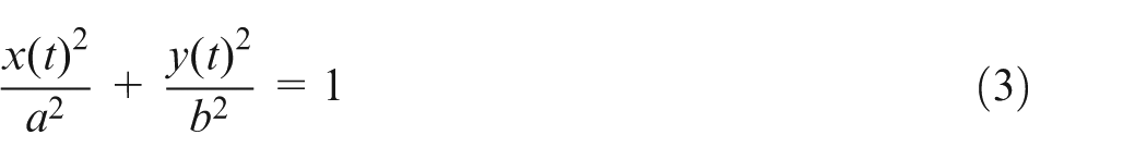
Based on Figures 1 and 2, suppose that the vibration locus in XY plane can be represented by
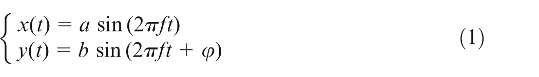
where f is the vibration frequency,
When
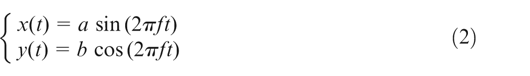
So, a standard elliptical equation can be written as
The cutting depth in the X-direction in RUEM is larger than that in CC (i.e. the radial unilateral increment


Therefore, the equation of motion locus for the random point of cutting edge in countersink cutter during RUEM can be represented by
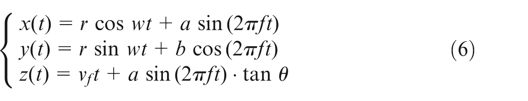
where r is the rotation radius of any point of tool cutting edge and
As a result, the cutting speed of the tool in the three-dimensional (3D) coordinate system during RUEM can be derived as follows
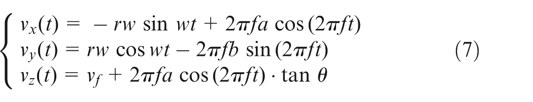
According to equations (4) and (5), the RUEM can achieve larger material removal volumes, countersunk hole diameter and depth compared with that in CC. Therefore, the lower height difference of the surface between the surface of CFRP workpiece and the surface of countersunk nail head can be obtained in RUEM than that in CC, as shown in Figure 3. Meanwhile, after the countersunk head screw is assembled, the more lower height difference of the surface, the better surface levelness.
Schematic of surfaces levelness for RUEM and CC.
If the coordinate system is established in the section of the PCD blade (i.e. the section of rotation radius when the PCD blade located at any instantaneous moment), the cutting speed in the Y-direction will be written as

During the RUEM, the
In addition, the RUEM can also be divided into the cutting modes of the separated and unseparated types.13,20 When
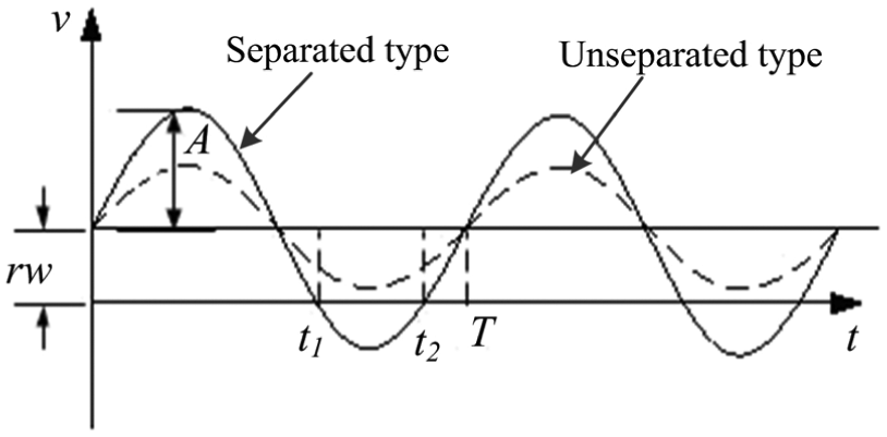
Unilateral speed curves of tool in RUEM of separated and unseparated types.
Figure 5 illustrates the hole surface morphology and tool blades’ path in RUEM of the separated and unseparated types compared to that in CC. Seen from Figure 5, larger material removal volumes and countersunk hole diameter can be obtained in RUEM of the separated and unseparated types in comparison to that in CC. Meanwhile, the residual material height (i.e. the uncut material height or cusps’ height)
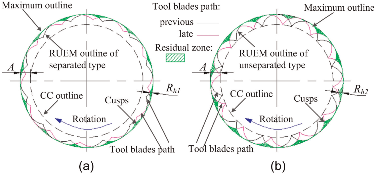
Hole surface morphology and tool blades’ path in RUEM compared to that in CC: (a) RUEM of separated type and (b) RUEM of unseparated type.
Based on the above analyses, it can be found that better cutting performance of the tool can be obtained in RUEM of the separated type in comparison to that in the unseparated type. Therefore, the RUEM method of the separated type for countersinking of CFRPs is investigated in this article.
Experiments
Properties of workpiece material
The workpiece material was a multidirectional CFRP panel with dimensions of 65 × 45 × 10 mm. It consisted of carbon fibers and epoxy resins. The carbon fibers are laid up in a repeating sequence of [−45°/0°/90°/45°]s orientation, as shown in Figure 6. The material properties of the workpiece are listed in Table 1.
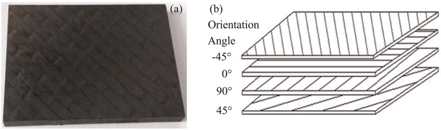
(a) CFRP specimen and (b) plies’ sequence of multidirectional CFRP panel.
Material properties of workpiece.
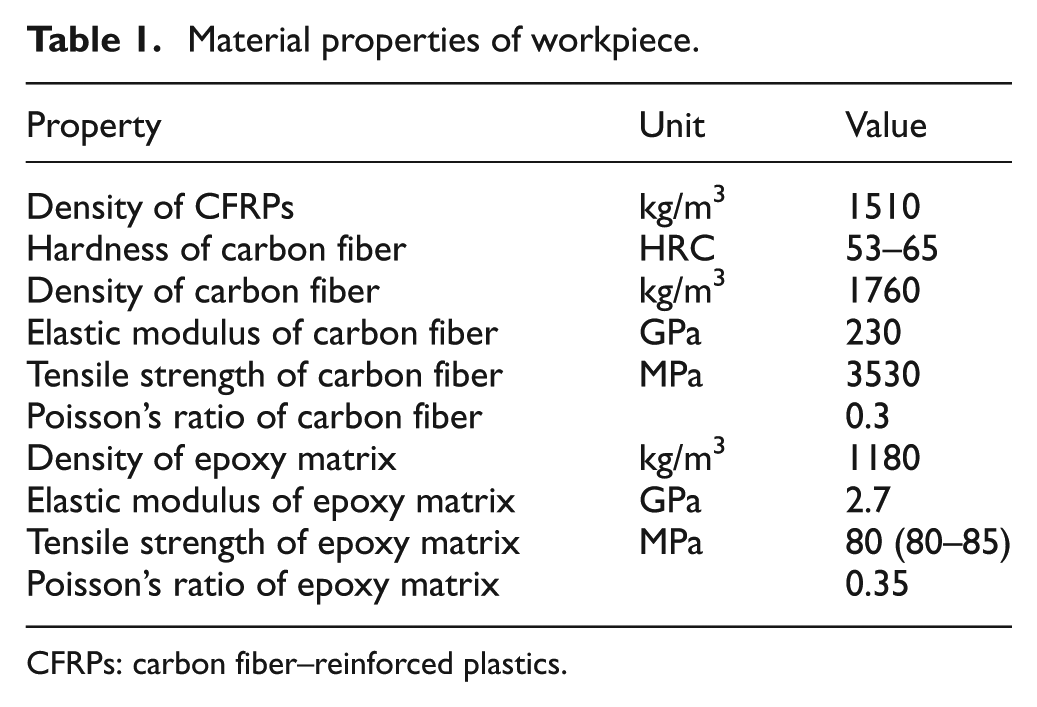
CFRPs: carbon fiber–reinforced plastics.
Experimental setup and conditions
Figure 7 shows the schematics of RUEM transducer and tool, which were composed of countersink cutter and rotary ultrasonic elliptical vibration transducer of sandwich piezoceramic rings.
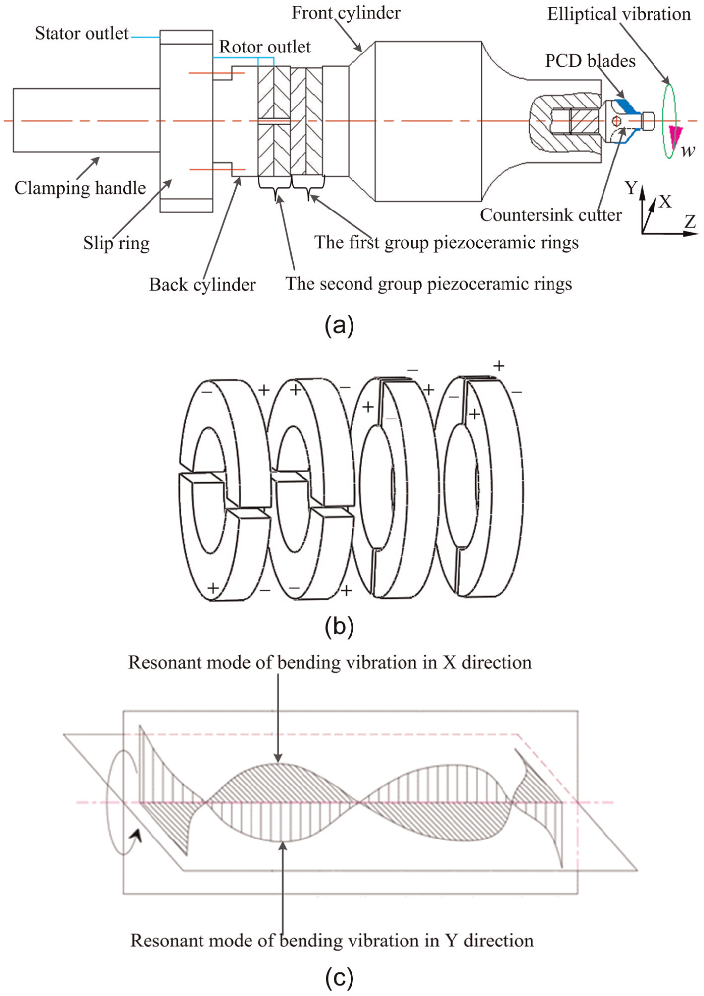
Schematics of RUEM transducer and tool: (a) RUEM transducer for countersinking of CFRPs, (b) piezoceramic ring structure and electrode of RUEM transducer and (c) vibration modes of RUEM transducer.
The countersink cutter comprised two PCD blades and countersink cutter body as well as manufactured by welding technology to weld PCD blades on the cutter body. The countersink angle was 100°. During RUEM, countersink cutter was connected to the rotary ultrasonic elliptical vibration transducer by screw thread in order to supply ultrasonic elliptical vibration in the XY plane and rotary motion, while the axial feedrate relied on the computer numerical control (CNC) machine as shown in Figure 10.
The rotary ultrasonic elliptical vibration transducer of sandwich piezoceramic rings consisted of the front cylinder with ladder-type horn, piezoceramic rings, back cylinder, rotary conductive slip ring and clamping handle. This sandwich transducer had many advantages such as the high output power, easy to be designed and assembled. 24 The material properties of ultrasonic transducer components are shown in Table 2.
Material properties of ultrasonic transducer and countersink cutter components.
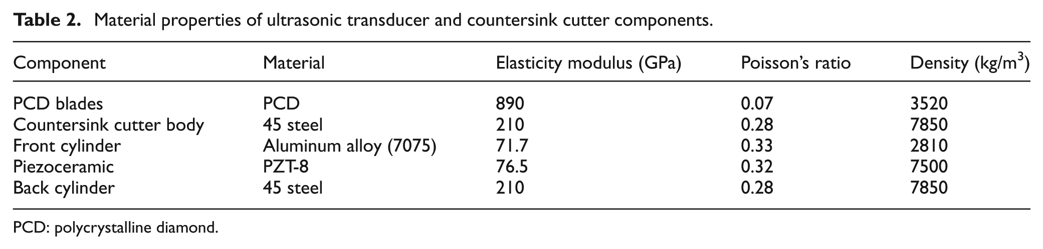
PCD: polycrystalline diamond.
According to the schematics of RUEM transducer and tool (as shown in Figure 7), the 3D models of RUEM transducer and tool were designed in Pro ENGINEER software and imported into ANSYS software so as to carry out modal analysis. Figure 8 shows the finite element model of RUEM transducer and tool with free meshing. Based on the modal analysis, the double directional bending vibration modes were obtained as well as the vibration frequencies of 28.447 kHz (see Figure 9(a)) and 28.562 kHz (see Figure 9(b)) were observed. Figure 9 also shows that the maximum displacement generated by piezoelectric transducer excite was located in the tool-tip. Finally, according to the designed schematics and simulated results, the ultrasonic elliptical transducer of double directional bending vibration was fabricated.
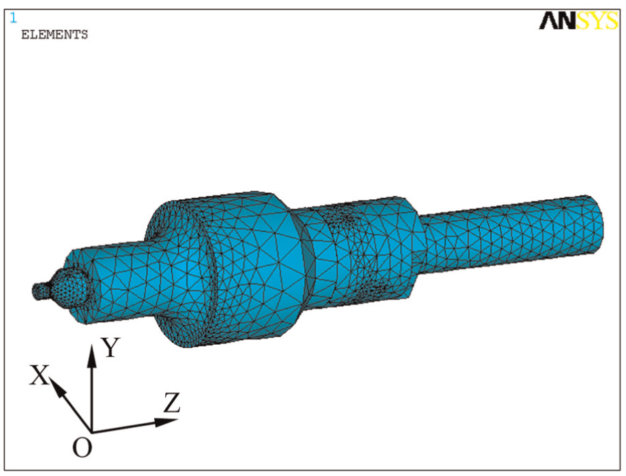
Finite element model of RUEM transducer and tool.
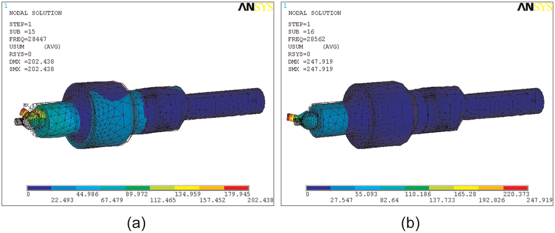
Double directional bending vibration modes and vibration frequency: (a) Y-directional bending vibration mode and (b) X-directional bending vibration mode.
Based on the modal analysis of ultrasonic transducer and tool, the simulated bending vibration frequency was about 28.5 kHz and the vibration location of maximum displacement was predicted. According to the simulated response frequency 28.5 kHz, the actual elliptical vibration frequency of double directional bending vibration was set. A laser micrometer system was employed to measure the ultrasonic elliptical vibration amplitude of tool, which comprised a laser micrometer controller (LK-G5000 series), a sensing head and LK-Navigator 2 software. LK-Navigator 2 is a software for configuring parameters and monitoring the LK-G5000 series controller. It was used by connecting a personal computer and the controller to configure the parameters and monitor operating status. The measured vibration amplitudes were 7 and 6 µm (i.e. a = 7 µm, b = 6 µm).
Therefore, the maximum cutting speed of the tool in the cutting direction was calculated as
Following, the experimental platform was set up, as illustrated in Figure 10. It shows the schematic for the measurement of the thrust force and cutting temperature during countersinking of CFRPs. In these experiments, the number of countersunk holes in RUEM and CC was three, respectively. The experimental platforms consisted of a CNC machine, a rotary ultrasonic elliptical vibration transducer, an ultrasonic power supply, a force measuring system, a temperature measuring system, countersink cutter, clamps and bolts. The experimental conditions are listed in Table 3.
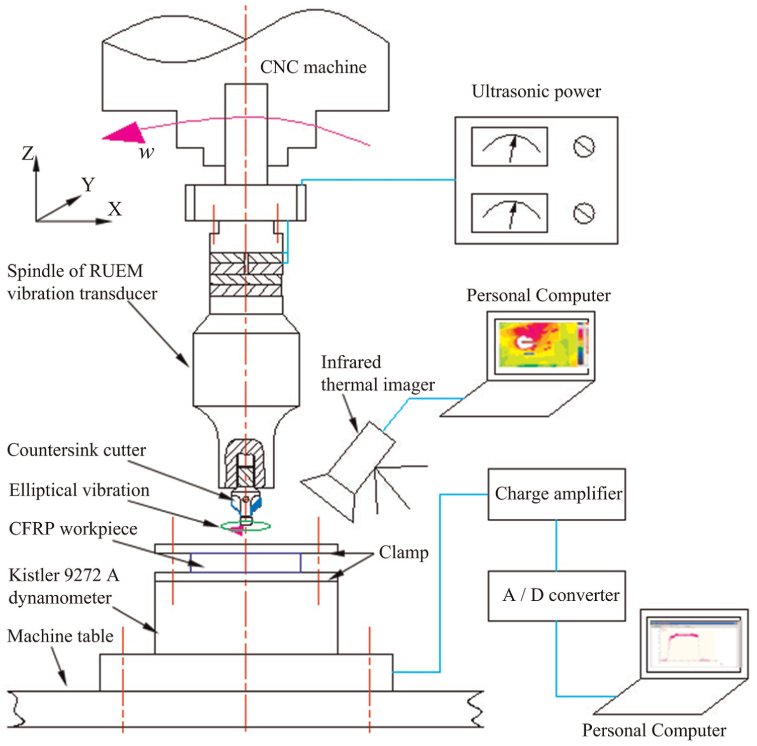
Schematic of experimental platform for the countersinking of CFRPs.
Experimental conditions.
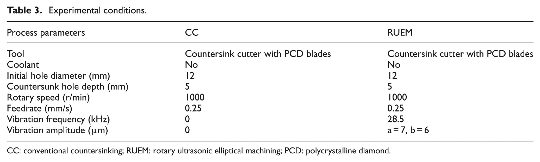
CC: conventional countersinking; RUEM: rotary ultrasonic elliptical machining; PCD: polycrystalline diamond.
Measurement of thrust force
A Kistler 9272A piezoelectric dynamometer was employed to measure the thrust force during countersinking. The force signals from the dynamometer were transmitted to Kistler 5070A charge amplifier and converted into digital signals by means of an analog-to-digital (A/D) converter. And then, the obtained digital signals were displayed and recorded on an industrial personal computer in virtue of Kistler Dynoware software, as shown in Figure 10.
Measurement of cutting temperature
A infrared thermal imager was applied to measure the cutting temperature at hole entrance during countersinking. The obtained temperatures were displayed and recorded on an industrial personal computer by means of IRBIS®3 Plus software, as shown in Figure 10.
Measurement method for surface levelness after RUEM and CC
Figure 11 illustrates the schematic of the surface levelness measurement between the surface of CFRP workpiece and the surface of countersunk nail head. The laser micrometer system was also used to measure the levelness, which consisted of a laser micrometer controller (LK-G5000 series), a sensing head and a personal computer with LK-Navigator 2 software. During the measurement of levelness, the measured workpiece was placed on the CNC machine table and the sensing head was fixed on the spindle of CNC machine by the magnet base; meanwhile, eight measured point positions (see Figure 11(b)) were successively selected along the diagonal of 45° by one-to-one relationship in the surface of nail head and CFRP workpiece, respectively. Besides, the height difference of the surfaces between CFRP workpiece and nail head measured by the sensing head was considered as the surface levelness.
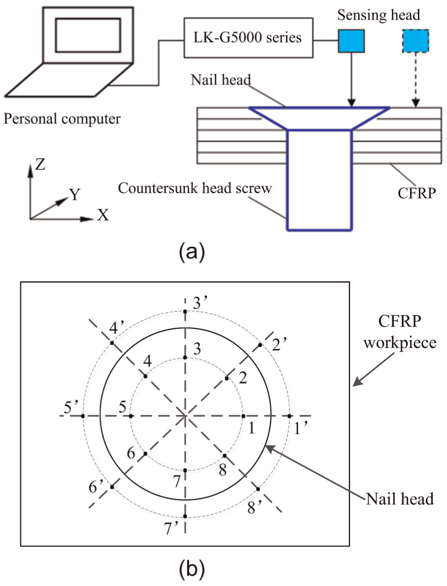
Measurement method of surface levelness: (a) schematic of the surface levelness measurement and (b) eight measured point positions in the surface of nail head and CFRP workpiece.
Experimental results and discussion
In the experiments, in order to accurately compare the surface levelness after RUEM and CC, the RUEM and CC were used, respectively, to machine a countersunk hole on a CFRP workpiece, and each experiment was repeated three times under the same experimental conditions (i.e. acquired three machined workpieces). During each experiment, the thrust force, torque and cutting temperature at hole entrance were measured and compared, as shown in Figures 12–14, respectively. Besides, in Figures 12–14, the serial number of countersunk hole in RUEM and CC on a CFRP workpiece was regarded as the same serial number so that the experimental analysis and comparison and the title (i.e. hole number) of horizontal axis in these graphs denoted the serial number of countersunk hole in RUEM and CC for the acquired three machined workpieces. And then, a machined CFRP workpiece was chosen from the acquired three machined workpieces based on the similar experimental results, as well as the surface integrity, hole accuracy and surface levelness were analyzed, as shown in Figures 15–18 and Table 4.
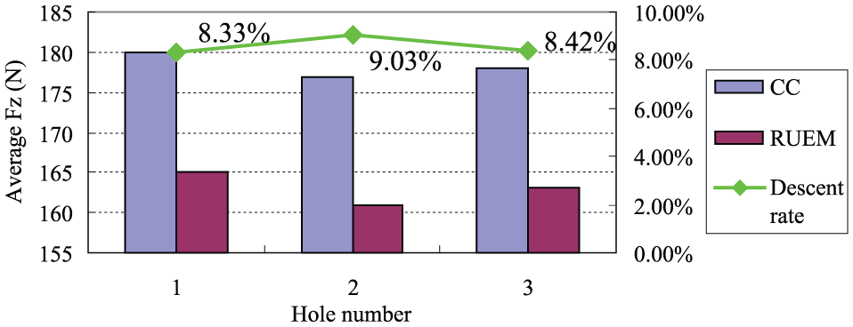
Average thrust force in RUEM and CC.
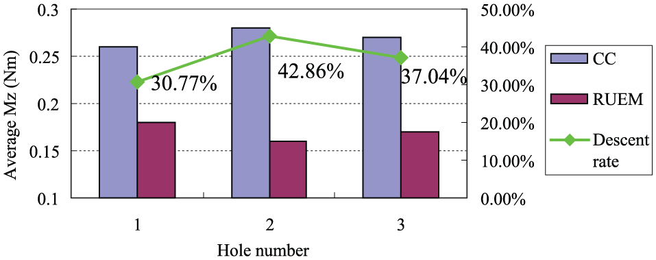
Average torque in RUEM and CC.
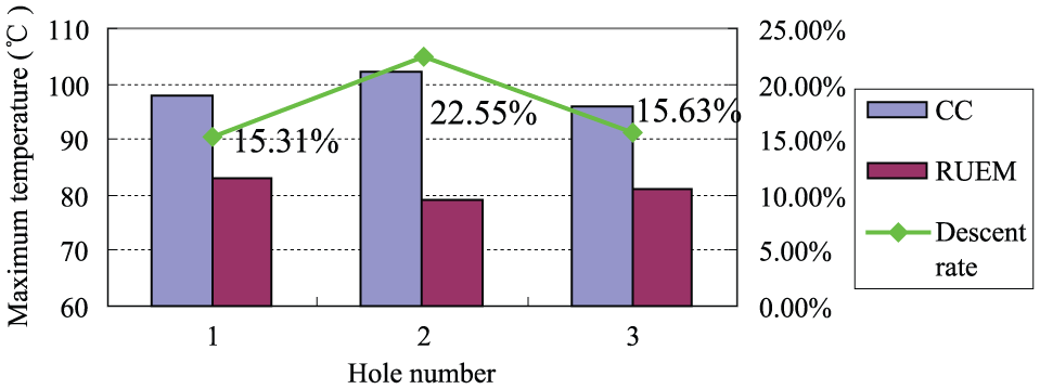
Maximum cutting temperature at hole entrance in RUEM and CC.
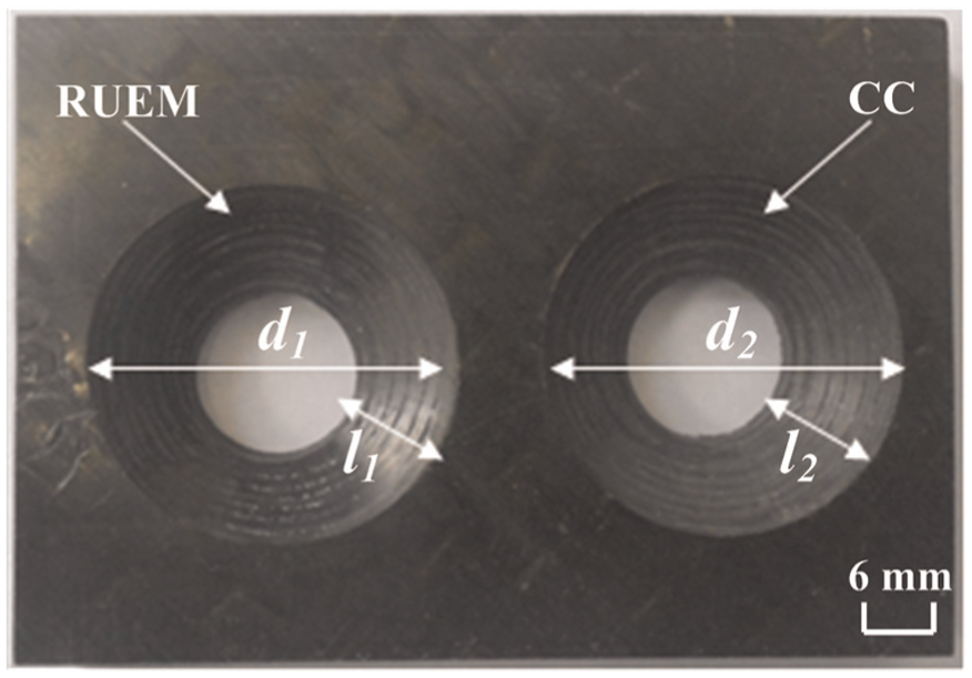
Countersunk holes after RUEM and CC.
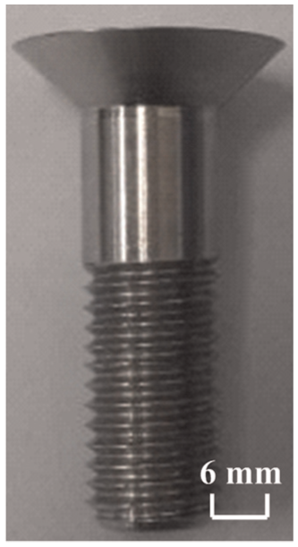
Countersunk head screw.
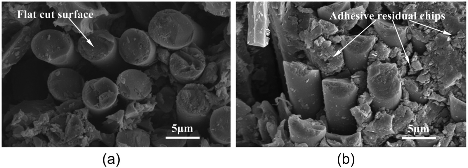
SEM micrographs of fibers’ fracture surface in the machined hole surfaces: (a) fibers’ fracture surface of RUEM and (b) fibers’ fracture surface of CC.
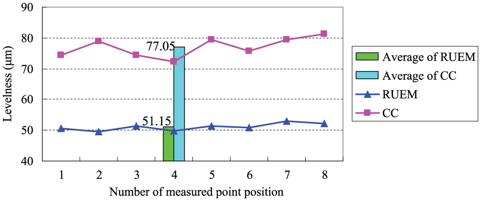
Surface levelness after RUEM and CC.
Comparison of the dimensional accuracy of countersunk holes for RUEM and CC.
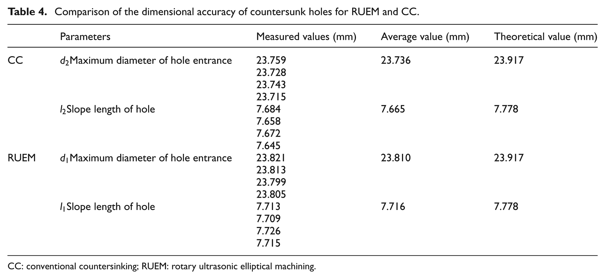
CC: conventional countersinking; RUEM: rotary ultrasonic elliptical machining.
Comparison of average thrust force for RUEM and CC
Figure 12 shows the obtained average thrust force in RUEM and CC. It can be seen from Figure 12 that the average thrust forces of RUEM were obviously lower than that in CC. Meanwhile, the maximum average thrust force in RUEM was about 165 N, while the maximum in CC was about 180 N. In addition, the descent rate of average thrust force in RUEM was about 8%–9% compared to that in CC.
Comparison of average torque for RUEM and CC
As shown in Figure 13, it can be observed that the average torques in RUEM were also clearly lower than that in CC. Meanwhile, the maximum average torque in RUEM was about 0.17 N m, while the maximum in CC was about 0.28 N m. Besides, the descent rate of average torque in RUEM was about 30%–43% in comparison to that in CC. The results were similar with the research results about the ultrasonic elliptical vibration drilling of CFRPs. 13
Comparison of maximum cutting temperature at hole entrance for RUEM and CC
Based on Figure 14, the following results can be observed. First, the maximum cutting temperatures in RUEM were also evidently lower than that in CC. Second, the maximum cutting temperature in RUEM was about 81 °C, while the maximum in CC was about 106 °C. Third, the descent rate of maximum cutting temperature in RUEM was about 15%–23% than that in CC.
Comparison of surface integrity and accuracy of countersunk holes for RUEM and CC
Figures 15–17 show the countersunk holes after RUEM and CC, countersunk head screw used in the surface levelness measurement after countersinking as well as the scanning electron microscopy (SEM) micrographs of fibers’ fracture surface in the machined hole surfaces, respectively.
In macroscopic view (i.e. seen in Figure 15), the surface integrity of countersunk hole in RUEM was better than that in CC, and the dimensional accuracy of countersunk hole in RUEM was superior to that in CC, as listed in Table 4. In microscopic view (i.e. seen in Figure 17), the fibers’ fracture surface was more flat and the adhesive residual chips (i.e. chips adhesion) of hole surface were less in RUEM than that in CC.
Seen from Table 4, compared with the CC, the RUEM obtained large material removal volumes and countersunk hole diameter, as well as the values of
Comparison of surface levelness for RUEM and CC
Figure 18 illustrates the surface levelness after RUEM and CC. In the diagram, the horizontal axis represents the point position of surface levelness measurement (see Figure 11(b)) for RUEM and CC. From Figure 18, the following results can be drawn. To begin with, the surface levelness of RUEM was better than that of CC significantly. Next, the average of surface levelness for RUEM was about 51.15 µm, while the average of surface levelness for CC was about 77.05 µm. Finally, compared with the CC, the RUEM improved the surface levelness between CFRP and countersunk nail head to about 33.6%, as well as kept the stability of cutting process for countersinking.
Discussion
(1) The thrust force, torque and cutting temperature could be effectively reduced in RUEM in comparison to that in CC. One reason for the results was that the RUEM made the tool generate an extra additional speed (i.e. tangential speed
(2) Owing to the material properties of CFRPs, it would result in the shrinkage cavity phenomenon after its processing. However, because the RUEM could effectively reduce the thrust force, torque and cutting temperature, the shrinkage cavity of CFRPs could be greatly improved. Consequently, the processing accuracy of countersunk hole as well as the assembly accuracy between the countersunk hole and countersunk head screw were closer to the theoretical value in RUEM than that in CC.
(3) The large material removal volumes, countersunk hole diameter and depth could be achieved in RUEM due to the specific cutting locus of RUEM compared with that in CC. Therefore, the lower height difference of the surfaces (i.e. the excellent surface levelness) could be obtained in RUEM than that in CC.
Conclusion
This article reported a feasibility study on the RUEM for countersinking of CFRPs for the first time. The processing principle of RUEM for countersinking was illustrated according to the countersinking models and equations of motion locus. Based on the processing principle, the tool blades’ path, the countersunk hole surface morphology and levelness in RUEM of the separated and unseparated types were analyzed compared to that in CC. In addition, the rotary ultrasonic elliptical transducer was designed and fabricated, and the experimental platform was set up. Finally, the experimental results were discussed and also verified the feasibility of RUEM for countersinking of CFRPs. Therefore, the following conclusions can be drawn from this study:
(1) The large material removal volumes, countersunk hole diameter and depth can be achieved in RUEM of the separated and unseparated types in comparison to that in CC. Therefore, the lower height difference of the surfaces (i.e. the excellent surface levelness) can be obtained in RUEM than that in CC. And the RUEM of the separated type can achieve better chip-removal effect and larger material removal volumes than that in RUEM of the unseparated type.
Meanwhile, the residual material height (i.e. the uncut material height or cusps height)
(2) The average thrust force, average torque and maximum cutting temperature at hole entrance can be reduced to about 8%–9%, 30%–43% and 15%–23% in RUEM of the separated type compared to that in CC, respectively. Therefore, the thrust force, torque and cutting temperature can be effectively reduced in RUEM of the separated type in comparison to that in CC. And then, the defects consisting of delamination, fiber pullout and tool wear can be reduced in RUEM of the separated type significantly.
(3) The flatness of fibers’ fracture surface, chip-removal effect, surface integrity and dimensional accuracy of countersunk hole can be significantly improved in RUEM of the separated type in comparison to that in CC.
(4) Compared with the CC, the RUEM of the separated type can improve the surface levelness about 33.6% and the stability of cutting process for countersinking.
Footnotes
Appendix 1
Declaration of conflicting interests
The author(s) declared no potential conflicts of interest with respect to the research, authorship and/or publication of this article.
Funding
The author(s) received no financial support for the research, authorship and/or publication of this article.