
Abstract
This article studies regenerative chatter in single-point face-machining at nominally constant speed under continuous conditions. A temporal model for rotational speed was developed and experimentally verified. The resulting rotational time-delay was cast into the classical force feedback mechanism for chatter. A chatter model was formulated to allow slight spindle speed variation about the temporal model. The modified method of steps was then employed to solve the tool vibration in time-domain allowing one (single-degree-of-freedom) or two (2-degree-of-freedom model) vibrational modes. Exploratory facing experiments using a grooving tool were conducted on a nickel alloy workpiece. It was found that the tool was more susceptible to chatter at larger diameters. It appeared that the single-degree-of-freedom model captured the most relevant of the observed phenomena while cutting without spindle speed variation, however, neither the 1-degree-of-freedom nor the 2-degree-of-freedom models could effectively capture the experimentally observed chatter evolution characteristics while cutting with spindle speed variation.
Introduction
Face-turning (facing) operations are an important class of machining operations, especially in aero-engine components such as blade-discs and in automotive components such as brake-discs. An important sub-class of facing, found abundantly in industry, is constant speed facing (CSF) where the rotational speed of the workpiece is varied inversely with the radial distance of the tool keeping the peripheral speed constant. Productivity, tool temperature and power consumption are more stable with CSF than with constant rotational speed. Though papers could be found in the machining literature related to facing,1–4 none of them treat the chatter phenomenon in CSF in such a manner as to capture both intrinsic and extrinsic spindle speed variation (SSV).
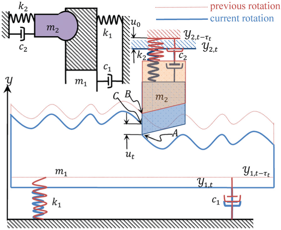
Consider a simple continuous facing operation as shown in Figure 1. For the subsequent descriptions, refer to Notation in Appendix 1. The instances of time-varying variables such as
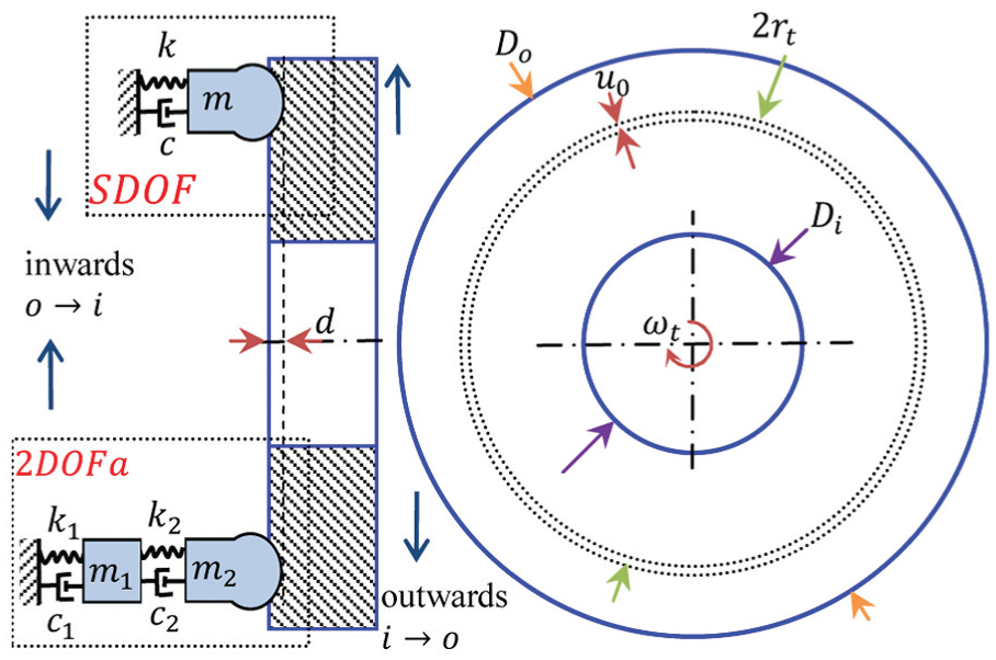
Schematic of facing: SDOF and 2DOFa models.
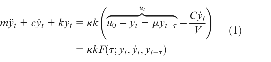
Suppose the workpiece is rigidly rotating at constant angular speed
Conditions of chatter stability have been important since they enable a field practitioner to choose tool geometry and cutting conditions judiciously. Equation (1) affords a stability boundary in this sense only when
Now suppose angular speed
An implicit calculation of
CSF
For CSF, in addition to
When the delay in equation (1) is time-varying as
For a given
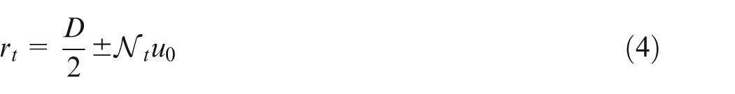

Equation (4) holds when
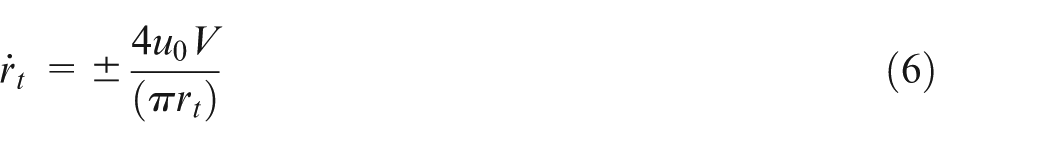
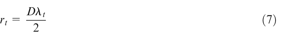
Equations (7)–(10) give the final results for
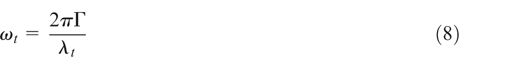
Significantly, a closed-form expression of
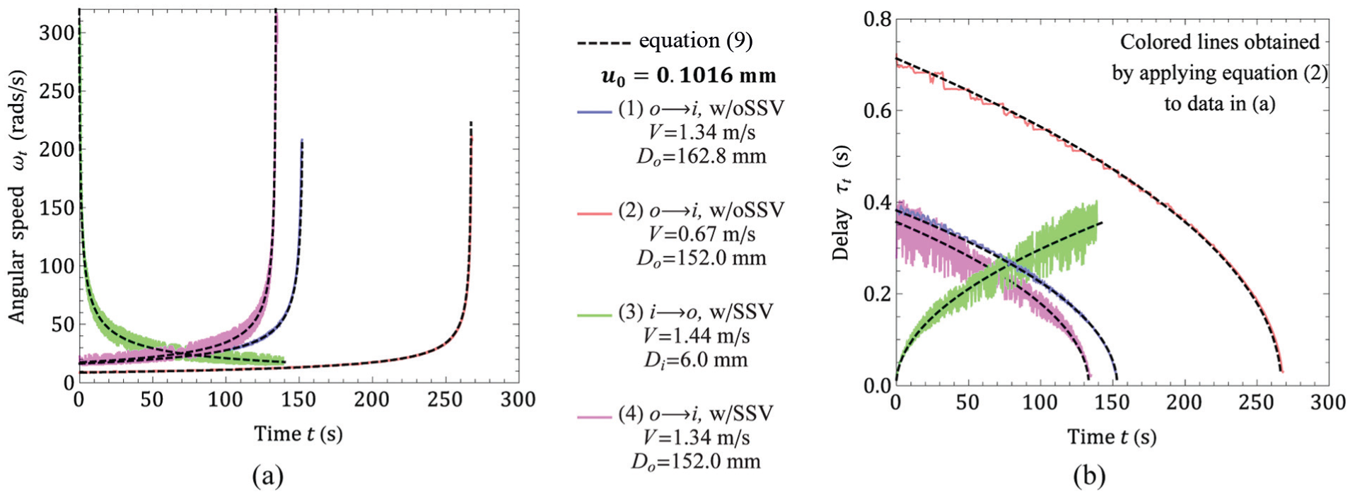
Experimental and modeled (a) angular speed ωt and (b) delay function τt.
With this background, this article proceeds to investigate chatter in CSF with and without SSV for both
Method of steps
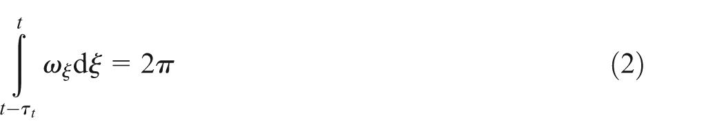
Referring to equation (2), as long as
Figure 3(a) shows a graphical outline of the approach taken to solve the tool vibration for SDOF. The total duration of travel of the tool over the workpiece surface is divided by sequence of time-instants
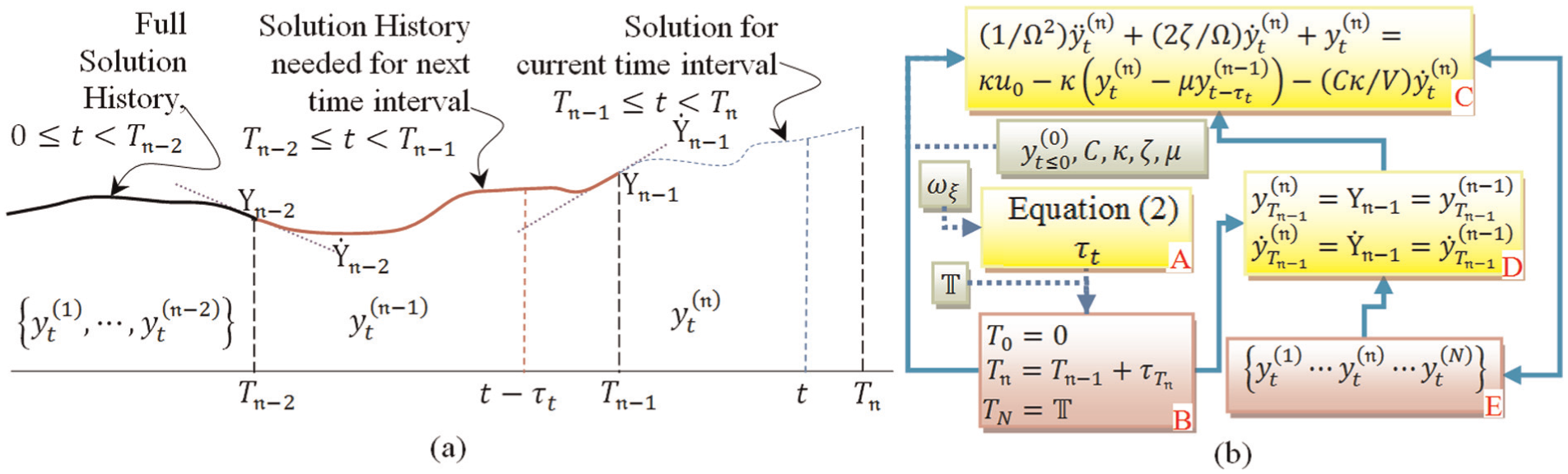
Tool vibration solution using modified method of steps: (a) graphical summary and (b) sequence of steps.
2DOFa and 2DOFb models
A similar procedure can be formulated when two modes are operational. In 2DOFa (Figure 1), the workpiece is assumed rigid as in SDOF and both modes are allotted to the tool. Alternatively, in 2DOFb (Figure 4), both the tool and the workpiece are compliant and one mode allotted each.
Schematic for 2DOFb model.
Let the index
In Figure 4, the 2DOFb model shown resembles that in Chung and Liu.
13
The derivation for
Experimental
A nickel alloy workpiece (Do = 152.0 mm, Di = 8.0 mm) was machined in a Haas ST10 CNC lathe (150 mm chuck size, ∼300 mm swing over bed). All cuts were performed at a depth of cut d = 0.381 mm and tool advance of u0 = 0.102 mm. SSV about the norm for CSF was achieved using machine controller parameters 165 (set to 100 rpm) and 166 (set to five corresponding to a 0.5-s period). Actual spindle speed was measured using a Compact Instruments (Model A2108/LSR) non-contact tachometer. The foregoing conditions were arrived upon after a number of trials to ensure that chatter was neither too feeble nor too violent.
A Sandvik RG123H079-16B-132BM grooving-type toolholder with a N123H2-0500-RO insert in the S05F grade was used. As shown in Figure 5(a), the toolholder was modified and inserted into the turret at a suitable length to excite a low (500–750 Hz) natural frequency as the primary mode, aided by finite element (FE) modeling on an exact computer-aided drafting (CAD) model of the tool. The modal tap-testing result of the tool workpiece system as assembled on the machine is shown in Figure 5(b).
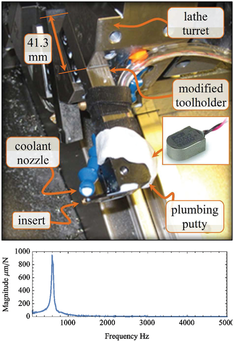
Tool/accelerometer (inset) arrangement and FRF: (a) assembly in turret and (b) FRF data.
A miniature PCB Electronics 352A72 accelerometer with a usable bandwidth of ∼8 kHz was glued firmly to the face of the toolholder behind the insert with Micro-Measurements M-Bond 200/200 and Catalyst C. Plumbing putty was applied all around in a ring and allowed to harden and seal the accelerometer from coolant. The guarded accelerometer cable was secured to the toolholder firmly using double-sided Velcro. Vibration data were collected at 100 kHz using a 12-bit data acquisition system simultaneously from the accelerometer and tachometer. During the cut, applying coolant through a nozzle directly on the top of the insert face from underneath was necessary to prevent premature insert breakage. The workpiece surface was cleaned with a rigid tool before taking the test cuts to prevent previous surface topography from interfering in the current cut.
In an attempt to confirm that
Results and discussions
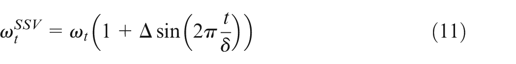
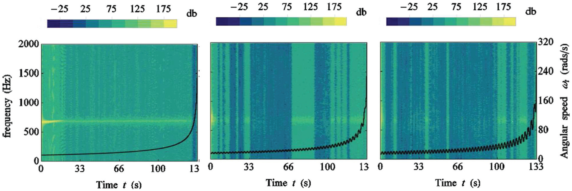
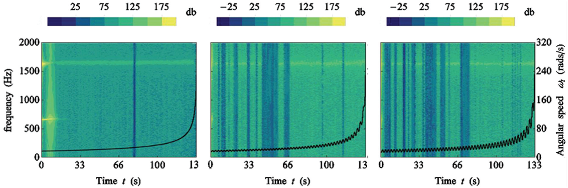
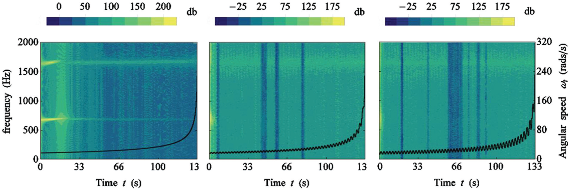
Acceleration data up to 2 kHz are sufficient to understand machining chatter and only this range is considered hereafter. Figure 6 shows data collected with the experimental setup of Figure 5. Here, the X-axis is the time axis. The rotational speed data of the tachometer appearing as black dots are referred to the right Y-axis. Fast Fourier transform (FFT) amplitudes of 1 s time fragments of the accelerometer data are plotted as gray scale dB values with the frequency referred to the left Y-axis. While Figure 6(a), (c) and (d) shows data collected at a nominal cutting speed of 1.34 ms−1, Figure 6(b) shows data collected at 0.67 ms−1 where chatter was completely avoided. Distinct striations are seen in these data, but this does not correspond to consecutive rotations of the workpiece. Data in Figure 6(c) and (d) are cases where SSV was imposed, also evident from the fluctuating
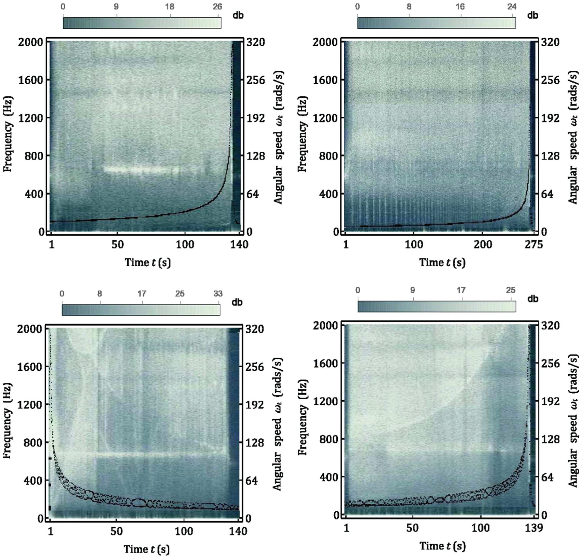
Experimental results: accelerometer data shown as a spectrogram with rotational speed data overlaid: (a) (o→i), w/o SSV; (b) (o→i), w/o SSV; (c) (i→o), w/SSV and (d) (o→i), w/SSV.
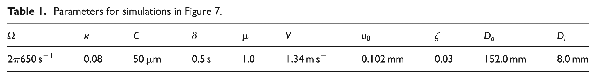
Parameters for simulations in Figure 7.
The authors were fully cognizant of the effect of tool wear and process parameters altering process damping14,15. However, tool wear and gross loss of size on the part were not noticeable at the end of the cut. Moreover, the tool ceasing to vibrate due to edge wear would likely have been indicated by dark bands at the end of the cut in Figure 6, but this is not readily evident. Furthermore, considering that a fresh edge was used for every cut in the final reported data, the assumption of a constant process damping parameter
The experimental results were then rationalized using the models assembled in a Mathematica® package. SSV was modeled as a sinusoidal fluctuation of
The goal of the model simulations was to replicate the chatter evolution characteristics seen in Figure 6. To enable direct comparison with experimental results, modeling results are also presented in a combined plot of modeled angular speed and acceleration spectrogram. However, instead of 1 s time-interval fragments, the spectrogram was assembled with modeled acceleration of each rotational period of the workpiece. The prior history of the acceleration input into the system did not affect the vibration solution for various combinations of parameters tested. There are three frequency regimes to be concerned with in understanding chatter here: the natural frequencies of the tool and/or workpiece (100–1000 Hz), workpiece rotational frequency (1–30 Hz) and SSV frequency (0–1 Hz). Since actual modal parameters were not available, multiple levels and combinations of parameters were simulated. In all the three models, the value of
Model results: SDOF (o→i) acceleration. Parameters given in Table 1. Increasing Δ: (a) Δ = 0%, (b) Δ = 10% and (c) Δ = 20%
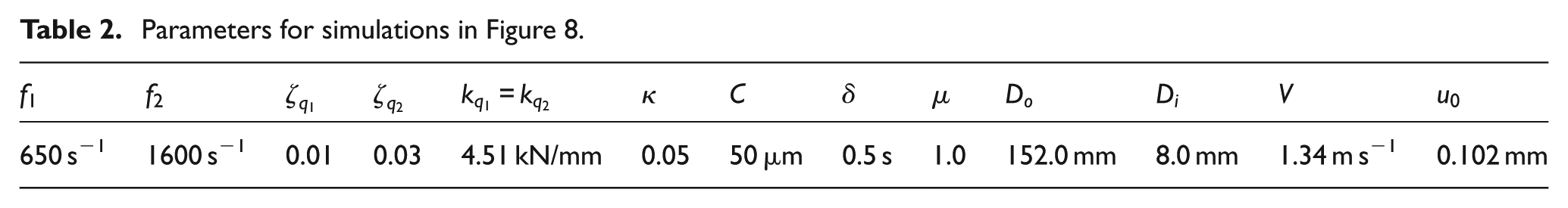
Model results: 2DOFa (o→i) acceleration. Parameters given in Table 2. Increasing Δ: (a) Δ = 0%, (b) Δ = 10% and (c) Δ = 20%.
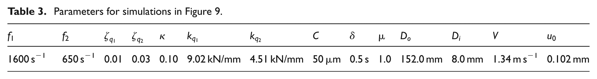
Model results: 2DOFb (o→i) acceleration. Parameters given in Table 3. Increasing Δ: (a) Δ = 0%, (b) Δ = 10% and (c) Δ = 20%.
Discussions
SDOF model
The data of Figure 6(a) suggest that the tool can be excited everywhere in the inspected bandwidth in the early part of the facing pass, and the dominant mode (DM) (∼650 Hz) can also be seen to become significant in the middle of the pass. Figure 7 shows results for SDOF (Figure 1),
Parameters for simulations in Figure 8.
Parameters for simulations in Figure 9.
2DOFa and 2DOFb models
In 2DOFa, both vibrational modes are allotted to the tool, while in 2DOFb, one mode is allotted to the tool and workpiece each. These models also predicted greater propensity for chatter at larger diameters. A likely reason is that at larger diameters, a greater number of vibrational waves occur in each rotation of the workpiece and the mismatch in phase of
In the former, SSV suppresses only the lower frequency mode while suppressing both the lower and higher frequency modes in the latter. In the former, the sporadic cessation of vibration is more frequent than in the latter. In Figures 8(a) and 9(a), one can see the cessation and then reactivation of the low frequency mode in the early part of the cut indicating mode interaction is expected to occur in the early part of the cut and not in the middle of the cut as in Figure 6(a). These facts taken together indicate that the true process physics of SSV is not really captured through the 2DOFa and 2DOFb models.
Some reasons may be speculated for the disagreement. The model for
Conclusion
The article studies the process dynamics in CSF. The temporal model of SSV intrinsically needed and the resulting time-varying process delay was derived and experimentally validated. Exploratory facing tests in a nickel alloy were performed with and without extrinsic SSV to understand chatter evolution. A SDOF and 2DOFa and 2DOFb were formulated and solved using the modified MOS. Tentative agreement was reached for experimental data for SDOF without SSV. However, with SSV, the tool workpiece interaction was more complex that chatter evolution could not be completely captured with the SDOF or the 2DOFa and 2DOFb models.
Footnotes
Appendix 1
Appendix 2
Acknowledgements
The authors thank UTRC for kindly allowing publication of this article. Eric Wold and Owen Gilbert of Connecticut Center for Advanced Technology are thanked for helping with the experimentation. Miroslav Baric and Konda Reddy Chevva, authors’ colleagues at UTRC, are acknowledged for discussions and the reviewers for their valuable input.
Declaration of conflicting interests
The author(s) declared no potential conflicts of interest with respect to the research, authorship and/or publication of this article.
Funding
The author(s) received no financial support for the research, authorship and/or publication of this article.