
Abstract
In this study, a new strategy is presented to increase the machining stability due to chatter suppression for boring and turning machining processes. The proposed approach is based on varying the position of stability lobes via changing mechanical properties of the tool body such as the mass and stiffness. Because of the shape of stability lobe diagrams, having a tool with a tunable stability lobe diagram can be useful to alter an unstable condition to a stable condition. For this purpose, a structure for the tool body is designed that is consisted of a hollow body with a core as a tunable screw inside it. As the core gets in or out, it changes the mass and stiffness of the tool body that leads to change the position of stability lobe diagram. In order to study the effect of designed structure on stability, the structure is simulated using a validated finite element time domain model. The time domain simulation shows a considerable improvement in stability of process. The strategy is experimentally applied to the process via modulation of the tool structure in the machining process to validate the simulation results. The experimental results have a high coincidence with theory and show a good improvement in stability.
Introduction
In the recent decades, machine tool vibration, that is also called chatter, has been a limitation for industrial machining. Chatter causes a poor surface finish, tool wear and decreasing of the tool life period. 1 Chatter also leads to reduce the production rate that will increase the production cost. Many researchers have widely studied chatter in machine tools in order to identify and control this phenomenon for improving the machining performance. A state-of-the-art review for machine tool chatter is presented by Quintana and Ciurana 2 giving a classification for chatter suppression methods to increase the machining stability process. Also, some techniques for the chatter stability prediction, chatter detection and chatter control, especially for the turning process, are reviewed by Siddhpura and Paurobally. 3
Chatter suppression methods are generally divided into active and passive control approaches. Active approaches are applied via control of the machine tool structure or machining parameters. Structural control systems use a feedback control system for vibration suppression of tool body or machine tool structure. These systems are consisted of sensor, actuator and controller units. Control algorithms, such as proportional–integral–derivative (PID), state space and fuzzy, are used by researchers in order to design these systems based on the dynamic modeling of the structure. A state-of-the-art review of active structural control strategies for a variety of machining processes using active materials such as piezoelectric materials, magnetostrictive materials, magnetorheological and electrorheological fluids as actuators and even sensors is presented by Park et al. 4 In order to suppress chatter in the milling process, in a more recent study,5,6 an active control system, using optimal control strategies, is designed, simulated and experimentally validated via a mechatronic system integrated into the spindle unit. Another chatter reduction method for boring and turning processes is proposed by Da Silva et al. 7 that is applied using piezoelectric patches in the tool holder connected to a passive shunt electrical circuit. Active structural control can also be applied to the structure via attachment of active vibration absorbers. Active absorbers studied by Ganguli et al.8,9 have variable damping as the control parameter for chatter suppression in turning and milling operations. Another tuned vibration absorber with variable stiffness is also studied for the milling process by Moradi et al. 10 that is effective over a wide range of chatter frequencies. Active structural control approaches are much effective, but expensive and complicated with professional usage and maintenance.
In the active process control approaches, machining geometry or machining parameters are changed purposively in order to avoid chatter. Online control of tool geometry for chatter suppression in turning process is investigated by Mei et al. 11 In this work, rake and clearance angles are changed due to online mitigation of chatter. Although, changing multiple machining parameters such as spindle speed besides cutting angle simultaneously can be more effective as investigated by Yang et al. 12 Variation of tool geometry may be easily applicable for turning and similar processes with one point of contact, but it might be a challenge for a milling tool with multiple contact points. However, offline chatter suppression is performed for a face milling tool via optimization of helix tool geometry by Yusoff and Sims. 13
The most popular active machining process control strategies are mainly depended on spindle speed variation for avoiding chatter. Spindle speed variation is applied to the machining process via a pseudo-random fashion 14 or sinusoidal.15,16 A formula is proposed to select the amplitude of spindle speed variation based on the internal energy analysis by Zhang et al. 17 Spindle speed variation with optimal amplitude of modulation besides an adaptive controller providing external force is investigated by Hajikolaei et al. 18 Spindle speed variation is also applied to the machining slowly and continuously to reach a stable zone on the stability lobe diagram in accordance with the lobe on the stability diagram where the process is located.19,20 Continuous spindle speed variation is also used as a chatter suppression strategy as it is investigated in the milling process by Bediaga et al. 21
Spindle speed variation methods seem to be effective for chatter suppression, but using these methods imposes a large inertial load to the rotating components of machine tool and also leads to decrease the tool life period as investigated by Albertelli et al. 22 The machining process stability does not merely depend on spindle speed and depth of cut, but it depends on other parameters like cutting angles as investigated in previous studies.11–13 The stability of the machining process in five-axis machining is determined by cutter orientations in addition to the depth of cut and spindle speed providing a posture stability graph by Wang et al. 23 . Choosing orientations only from the stable zone of the posture stability graph, chatter avoidance can be achieved without tuning other process parameters like spindle speed. Passive or offline vibration reduction methods are simple but effective methods and successfully applied for chatter reduction. These methods have limited abilities in comparison with active methods, but they are very simple to use and maintain, without much complications. These methods are applicable to the geometry, as mentioned before, or to the structure for chatter reduction. Tuned vibration absorbers, those are attached to the structure, are widely used for this purpose, for example, passive dynamic vibration absorbers attached to a boring bar on tool vibration is investigated by Miguelez et al. 24 to raise the minimum values of stable depth of cut on stability lobe diagrams. These dampers can also be attached to the workpiece such as the damper with a frictional component studied by Wang. 25 Also, multiple vibration absorbers attached to a collet chuck are used for chatter suppression in milling operations. 26 As a passive damping solution to minimize the vibration during milling operation on thin wall casings, tuned viscoelastic dampers are used by Kolluru et al. 27 focusing on the change in coupled interaction between tool and workpiece. Furthermore, for chatter suppression in turning, an optimal viscoelastic dynamic absorber is designed using non-linear optimization techniques by Bavastri et al. 28
Frictional dampers for increasing damping ratio of the system to achieve higher stability limits are other passive tools, as they are used for milling 29 and boring 30 operations.
In this article, a novel mechanism for chatter reduction is proposed that can be applied to the process via either active or passive approach. The main idea is taken from Smith et al., 31 which investigates the effect of milling tool length on metal removal rates. This article shows that sometimes longer tools can provide higher metal removal rates than shorter tools. The reason is change in frequency of the tool, due to the length, that changes the position of the stability lobe diagram. Therefore, for a specific point, on the stability lobe diagram, the frequency of the tool can be selected in a way that the most stable zone matches that point. Since online variation of the tool length during a machining process is a very challenging problem, in this article, a different mechanism is proposed for the tool structure to vary the tool frequency. The proposed structure is mainly consisted of a moving core inside the tool body. Online control can be applied to this structure, but in this article, as the first study, offline modulation is applied to the process to increase the machining process stability and material removal rate. The effect of this mechanism is investigated through numerical time domain simulation and experimental testing.
Modeling and simulation of the structure
As mentioned above, the proposed structure in this article is consisted of a moving core inside an axial hole in the tool body. In order to make the core moving inside the tool body, the core is designed as a bolt inside the axial hole of the tool body, and the hole is threaded as well. The threads of the bolt and the hole must have a very exact tolerance to fit properly. A schematic of this structure is shown in Figure 1 as a sectioned view for better understanding. The tool is clamped inside the fixture and as it is illustrated in Figure 1 the total length of the tool body (L) is obtained to be L = Lc + Lf, where Lc and Lf are, respectively, clamped and free lengths of the tool. The parameter Lt gives the length of threaded hole on free part of the tool length that is measured from the start of free length to the end of the hole. The parameter Lh is a variable parameter that gives the hollow length of the tool body that depends on the position of the bolt, for example, if Lh/Lt = 0, it means that the bolt is completely screwed inside the tool body as it reaches the end of the hole that makes the tool body similar to a solid body, and if Lh/Lt = 1, the bolt is completely screwed out of the hole and the tool body is a hollow body. The proportion Lh/Lt can be varied between 0 and 1 to create different natural frequencies of the tool body.
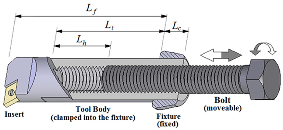
Sectioned view of the tool body, clamped to the fixture, with a bolt as a moving core inside it.
In order to investigate the effect of the proposed mechanism on the boring process, a time domain model is established and simulated. The model of cutting force is taken from the classical model presented by Tobias et al. 32 that gives the chatter force imposed to the tool tip in radial direction (Fy) as the following equation

where
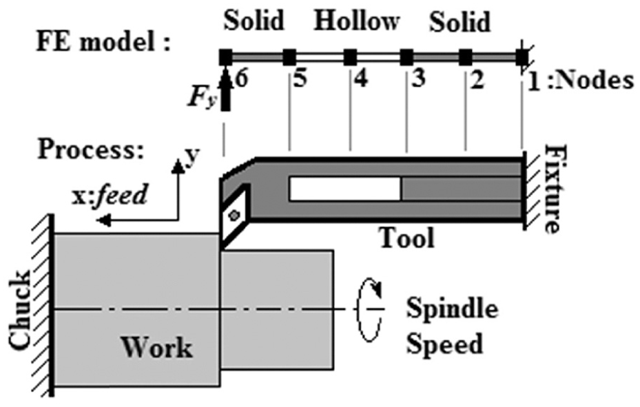
The boring process with finite element modeling.
The solid and hollow elements are different in section area and moment of inertia. In order to calculate the area or moment of inertia for a hollow section, the area or moment of inertia of the hole should be subtracted from the solid section. The system model is now presented as the following
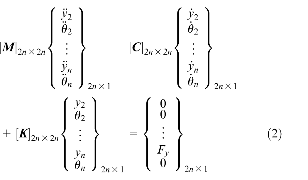
where [

where [
Hereon, a common boring tool is considered as a real case for modeling and numerical investigation of the effect of the proposed mechanism. The tool body is in cylindrical form with diameter of D = 25 mm and free length of Lf = 250 mm. Note that the total length of the real tool is about L = 340 mm, and 90 mm of its length is clamped inside the fixture as Lc. The length of the hole inside the free length of the body is equal to Lt = 190 mm with a diameter of about 13 mm that becomes d = 14 mm accounting the depth of threads. Note that the geometry of the hole is limited because of the tool body dimensions. The same geometry is considered for the core bolt. The material for the tool body and bolt is considered to be made of steel with elasticity modulus of E = 210 GPa and density of r = 7800 kg/m3.
Mass and stiffness matrices are built and the tool is modeled with five Euler–Bernoulli beam elements (n = 5) due to a convergence analysis based on first natural frequency
Finite element model convergence analysis and validation due to the first natural frequency of the tool.
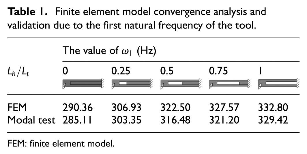


FEM: finite element model.
The damping ratios for first, second, third and the fourth modes of the tool, for different cases of Lh/Lt, are extracted from modal test to be, respectively, about 0.018, 0.01, 0.007, and 0.005. Having damping ratios the damping matrix ([
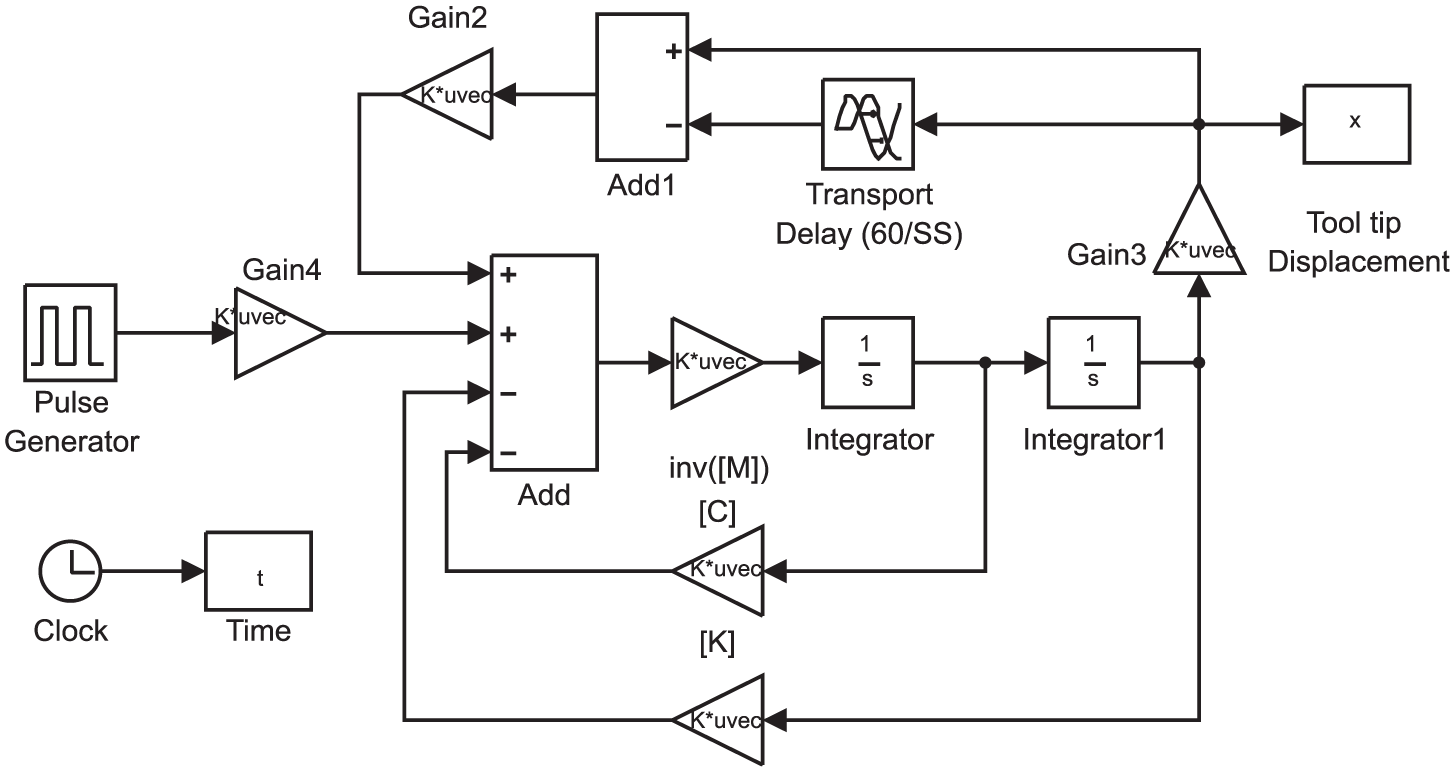
Time domain simulation of the boring process using Simulink of MATLAB.
Figure 4 illustrates the stability lobe diagrams, obtained from the time domain simulation, for different ratios of Lh/Lt. It can be seen that having the ability to change the ratio of Lh/Lt, makes it possible to have more stable zone on stability lobe diagram, that is, for each spindle speed a ratio of Lh/Lt can be found that will give the biggest value for the maximum stable depth of cut. Figure 4 illustrates that the proposed mechanism divides the stability lobe diagram into three zones: stable zone, unstable zone and the stabilizable zone. The stabilizable zone is consisted of machining speeds and depths of cut those are stable or can be stabilized via tuning of the tool. As a sample, consider a point on the stability lobe diagram with spindle speed of 3000 r/min and depth of cut equal to b = 0.6 mm. Figure 4 shows that this point is above the stability limit for Lh/Lt = 0, 0.25 and 1, but it is under stability limit for Lh/Lt = 0.5. Therefore, this point can be stabilized via tuning the core to achieve Lh/Lt = 0.5.
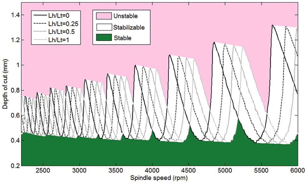
Different SLDs for different values of Lh/Lt, obtained by time domain simulation.
Figure 5 shows the displacement of the tool tip due to the vibration in the time domain for different values of Lh/Lt. It can be seen that the boring process at spindle speed of 3000 r/min is more stable when Lh/Lt = 0.5 rather than solid or hollow tool bodies. Similar results can be deduced for other spindle speeds. For some other samples, consider spindle speeds of 3770, 4580 and 5250 r/min on stability lobe diagrams illustrated in Figure 4. For spindle speed of 3770 r/min, the highest stable depth of cut is achievable on stability lobe diagram of the solid tool or when Lh/Lt = 0. This is due to the position of this spindle speed that is below the peak of stability lobe diagram of the solid tool. Similarly, spindle speed of 4580 r/min is below the peak of the stability lobe diagram of the tool with Lh/Lt = 0.5. The same condition can be seen for spindle speed of 5250 r/min that is below the peak of stability lobe diagram of the hollow tool with Lh/Lt = 1. For other spindle speeds which are not below a peak of stability lobe diagrams, the stability limit can also be increased by tuning of the tool, for example, for spindle speeds of 5250–5560 r/min, the maximum stable depth of cut can be achieved by Lh/Lt = 1 and for spindle speeds of 5560–5650 r/min, the maximum stable depth of cut can be achieved by Lh/Lt = 0.
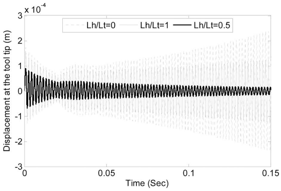
Displacement due to the tool tip vibration in time domain for different values of Lh/Lt, spindle speed: S = 3000 r/min and depth of cut: b = 0.6 mm.
In this section, the effect of proposed mechanisms for achieving higher stability limits in boring process is investigated theoretically via time domain modeling and simulation. The results denote the effectiveness of the method. The mechanism needs to be experimentally applied to a boring process for assurance about its performance. The experimental results are discussed below.
Experimental results
As mentioned before, a modal test is performed for model validation that guaranteed the accuracy of modeling. In order to show the effectiveness of the proposed approach for stabilization of the boring process, an experimental cutting test is performed via sound analysis chatter detection. 33 The structure is manufactured using spark machining of the tool body to shape an accurate axial hole inside it. Both hole and the bolt are threaded fine with a pitch of 0.9 mm to be exactly fitted. The hole inside the tool body is tapped using a FP4ME computer numerical control (CNC) milling machine and the screw is threaded using a TC-20 threading lathe CNC machine. The dimensions and material properties of the manufactured structure are the same as the modeled structure in previous section (Figure 6(a)). The boring tool with moveable core is installed on a HCS-32B CNC lathe machine tool to be evaluated cutting an aluminum cylindrical workpiece via sound analysis (Figure 6(b)).
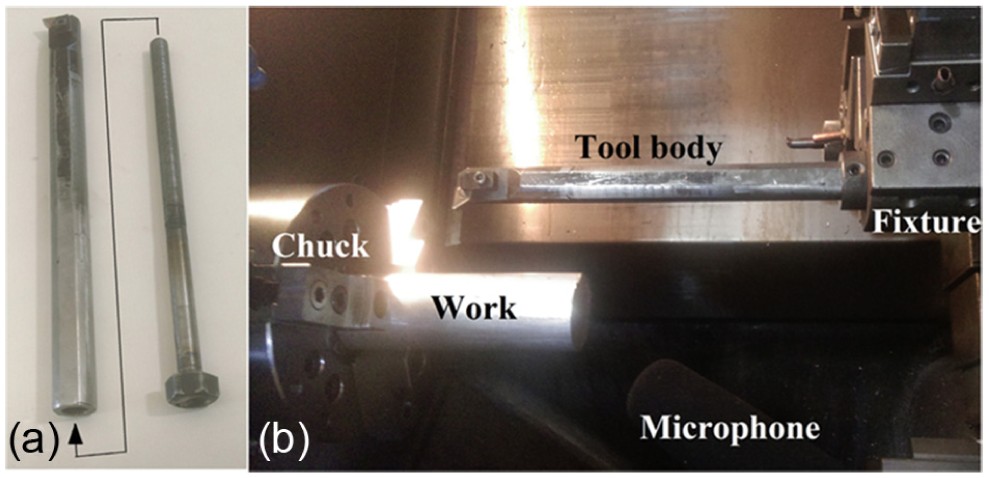
(a) The structure of fabricated tool and (b) the experimental setup for cutting test.
In order to investigate the effect of mechanism experimentally, some working points from the stabilizable zone of Figure 4 are chosen to be tested in different conditions of the structure (Lh/Lt = 0, 0.5 and 1). In all of these points, the depth of cut is b = 0.6 mm and the spindle speeds equal to 3000, 3800, 4600 and 5400 r/min are experimentally tested. Figure 7 is an enlarged view of Figure 4, which shows the position of these points due to the obtained stability lobe diagrams. In Figure 7(a), it can be seen that at spindle speed of 3000 r/min, the working point with b = 0.6 mm is below the stability lobe diagram for Lh/Lt = 0.5 and above the stability lobe diagram for Lh/Lt = 0. Therefore, it is expected that the boring process is stable in this point for Lh/Lt = 0.5 and it is unstable for Lh/Lt = 0. Similar result can be deduced from Figure 7(b) that shows the boring process is stable at spindle speed of 3000 r/min and b = 0.6 mm for Lh/Lt = 0 and it is unstable for Lh/Lt = 0.5 and 1. Also noting Figure 7(c), it is observed that the working point for spindle speed of 4600 r/min is stable for Lh/Lt = 0.5 and 1 and unstable for other values of Lh/Lt. From Figure 7(d), it is similarly deduced that the process for spindle speed of 5400 r/min and b = 0.6 mm will be stable for Lh/Lt = 0 and unstable for Lh/Lt = 0.5 and 1. In order to avoid redundancy, the case Lh/Lt = 0.25 is not discussed; however, this case can be investigated to obtain similar results just like the others.
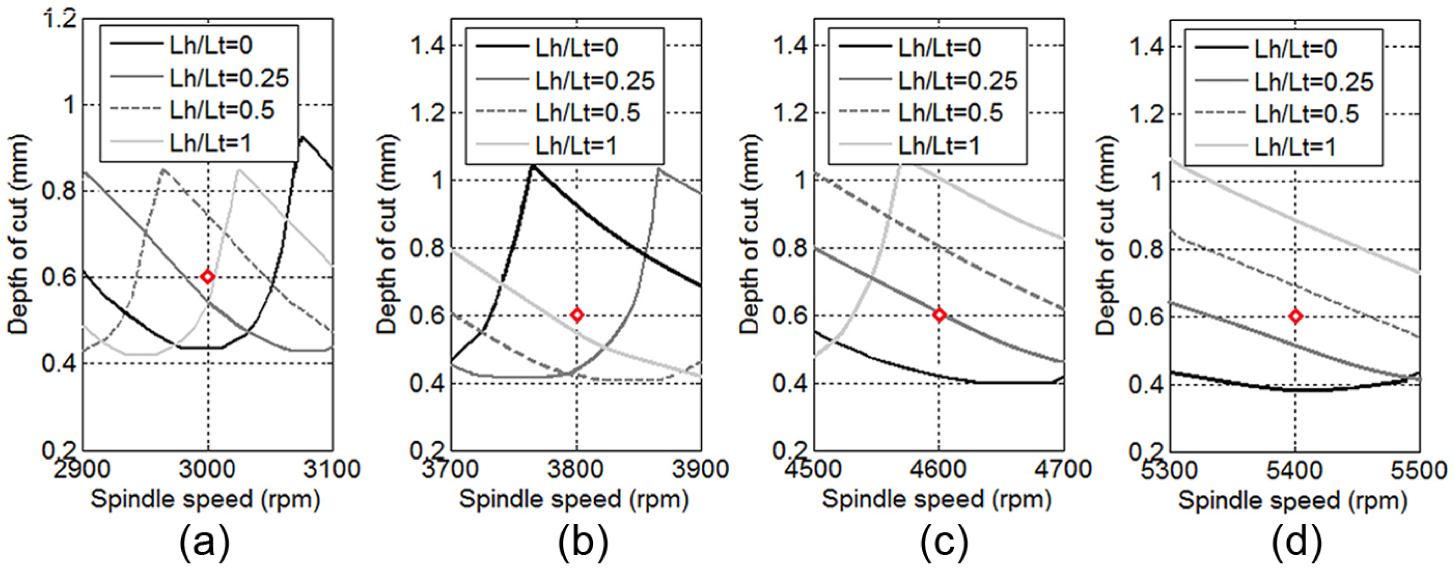
The position of selected working points with b = 0.6 mm as the depth of cut and spindle speeds of (a) S = 3000, (b) S = 3800, (c) S = 4600 and (d) S = 5400 r/min.
The sound of machining process is recorded via a microphone as a 16-bit mono wav file with 44.1 kHz sampling frequency and analyzed in the frequency domain using MATLAB FFT.
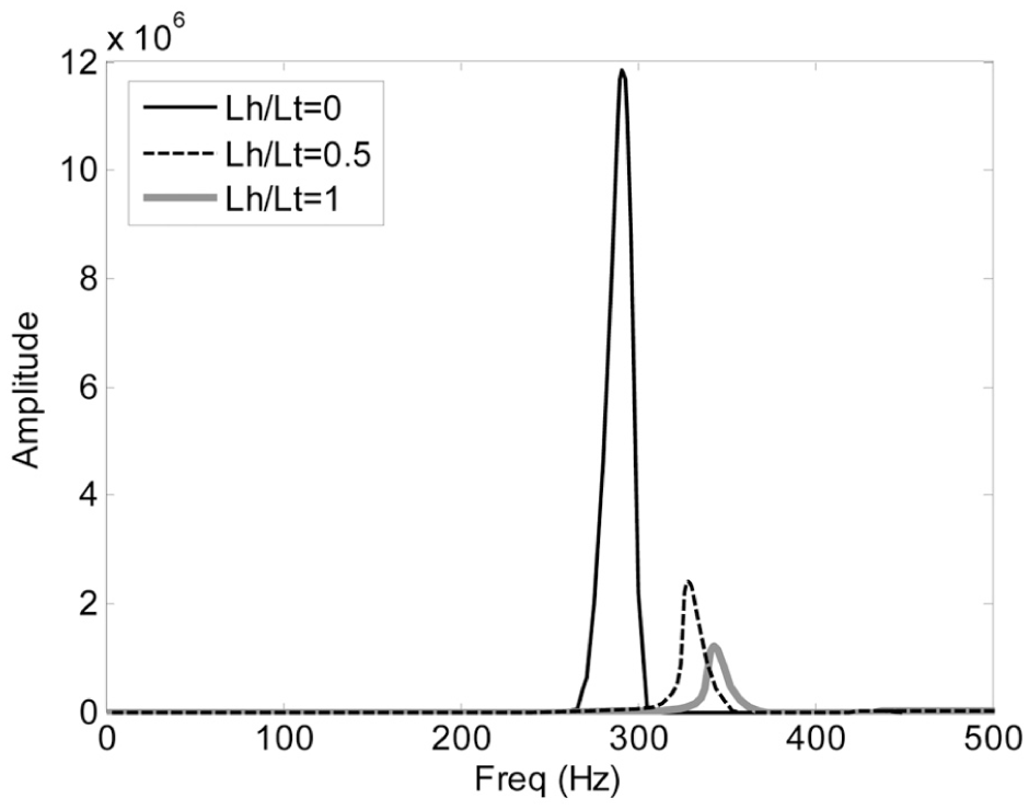
As a sample of experimental results, resulted frequency spectrums are depicted in Figure 8. In Figure 8, the frequency spectrum of the process sound for spindle speed of 3000 r/min and b = 0.6 mm is shown, where the maximum amplitude in chatter frequency, about the first natural frequency, belongs to the case Lh/Lt = 0 and the minimum amplitude belongs to the case Lh/Lt = 0.5. It is deduced that the tool with Lh/Lt = 0.5 can alter the process from an unstable zone to a stable zone, as it is investigated in modeling section. Also, the process seems to be nearly unstable for Lh/Lt = 1.
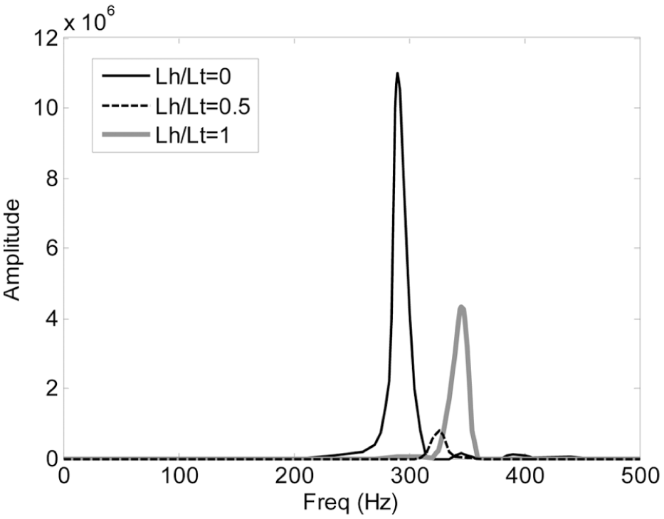
The frequency spectrums of process sound for different values of Lh/Lt, spindle speed: S = 3000 r/min and depth of cut: b = 0.6 mm.
Similar results shown in Figures 9–11 are experimentally obtained for spindle speeds of 3800, 4600 and 5400 r/min, respectively. The frequency spectrums shown in Figure 9 show that for spindle speed of 3800 r/min and b = 0.6 mm, the maximum amplitude in chatter frequency occurred when Lh/Lt = 0.5 and the minimum amplitude is achieved for solid tool body or when Lh/Lt = 0.
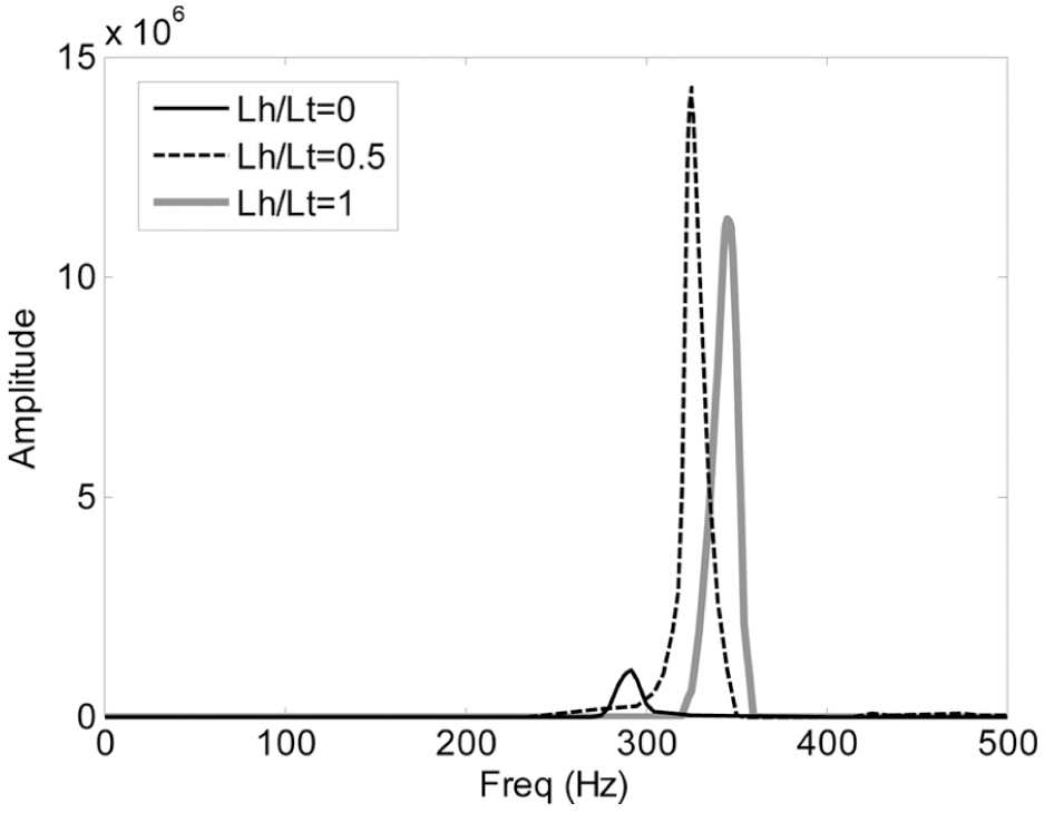
The frequency spectrums of process sound for different values of Lh/Lt, spindle speed: S = 3800 r/min and depth of cut: b = 0.6 mm.
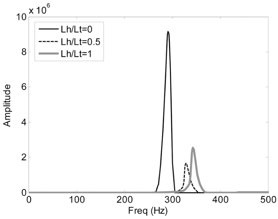
The frequency spectrums of process sound for different values of Lh/Lt, spindle speed: 4600 r/min and depth of cut: 0.6 mm.
The frequency spectrums of process sound for different values of Lh/Lt, spindle speed: S = 5400 r/min and depth of cut: b = 0.6 mm.
Figure 10 shows that the most stable boring process for spindle speed of 4600 r/min and b = 0.6 mm can be achieved via when Lh/Lt = 0.5. It is observed that the process is stable for a hollow tool (Lh/Lt = 0) as well.
As it was expected, due to the amplitudes of sound process, Figure 11 shows that the stable boring process for spindle speed of 5400 r/min and b = 0.6 mm can be achieved via hollow tool or when Lh/Lt = 1.
The resulted surface finish on workpiece is also shown in Figure 12 for spindle speed of 3000 r/min and b = 0.6 mm. It can be seen that the most smooth surface finish is obtained by tuning the structure to achieve Lh/Lt = 0.5, where the process is expected to be stable (Figure 12(c)). The process is unstable when Lh/Lt = 0 that represents a solid traditional tool (Figure 12(a)) and it is marginally stable when Lh/Lt = 1 (Figure 12(b)).
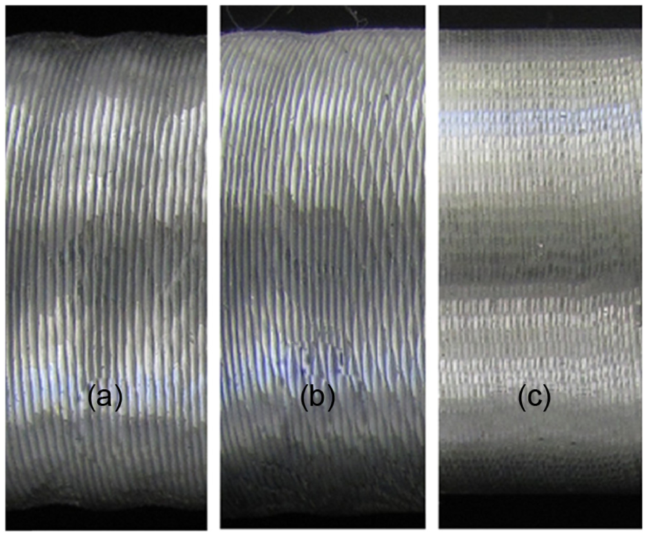
The resulted surface finish on workpiece for spindle speed of S = 3000 r/min and b = 0.6 mm: (a) Lh/Lt = 0 (unstable condition), (b) Lh/Lt = 1 (marginal stable condition) and (c) Lh/Lt = 0.5 (stable condition).
Noting both audio analysis and surface finish vision, similar results are concluded from experiments for other investigated cutting conditions. For these conditions, S = 3800, 4600 and 5400 r/min with b = 0.6 mm, the most stable machining processes are observed when Lh/Lt = 0, 0.5 and 1, respectively. The obtained results are in a good coincidence with modeling results and show the effectiveness of the proposed method.
Conclusion
In this article, a new method is proposed for chatter suppression based on changing natural frequency of the tool via a moving core inside the tool body. Changing natural frequency of the tool leads to change the position of the stability lobe diagrams. Thus, in a cutting condition for a specified spindle speed and depth of cut, the stability condition of the process can be altered to achieve more stability. The proposed mechanism is applied to a boring tool for showing its performance. The mechanism is modeled in the first step using a finite element model that is validated by modal test results. Modeling and simulation results show a considerable improvement in machining stability zone on stability lobe diagram. For the machining case that is investigated in this article, stability zone on stability lobe diagram is increased about 20%. This increasing in stability can be achieved by tuning the core position. After modeling, the mechanism is experimentally tested through sound frequency analysis chatter detection. Experimental results validate the modeling results and show the effectiveness of the proposed mechanism clearly. The novel proposed mechanism in this article opens a new scope in chatter suppression methodology.
In this study, as the first step, the mechanism is applied to the boring process in a passive way, as a tunable parameter, while it can also be applied to the machining process as a semi-active strategy for online chatter suppression via changing mass and stiffness in the chatter equation instead or beside variation of tool geometry and spindle speed. A weakness of the proposed method is its limited capability that can be improved using active control for the structure in future works. The core can be online modulated continuously or varied harmonically similar to previous studies.14–20 This mechanism can also be applied to any other kind of machine tools with slender tools, such as endmills. It is simple to fabricate and use in every factory. Despite the spindle speed variation, it does not impose any momentum to the heavy, rotating parts of the machine tool and it seems to have no direct effect on cutting edges as studied by Albertelli et al. 22
Footnotes
Appendix 1
The obtained values for mass and stiffness matrices of the tool body are as the following.
For Lh/Lt = 0, we have
For Lh/Lt = 0.25 we have
For Lh/Lt = 0.5, we have
For Lh/Lt = 0.75, we have
For Lh/Lt = 1, we have
Acknowledgements
The authors express their gratitude to Ahmad Moumivand (father), MSc, and Ali Moumivand (son), MSc, the managers of Marpich Bakhtar Company (MBC) in Kermanshah, Iran, for the experimental results. The authors also do appreciate engineer Sahab Moradi and Technician Mehdiabadi for their assistance in this project.
Declaration of conflicting interests
The author(s) declared no potential conflicts of interest with respect to the research, authorship and/or publication of this article.
Funding
The author(s) received no financial support for the research, authorship and/or publication of this article.