
Abstract
As a common phenomenon, chatter is one of the most important factors that inhibit the improvement of productivity and deteriorate the machined surface quality in milling process. In this article, the mathematical model of the dynamic machining process is first constructed with multi-delays, in which the effect of the cutter’s helix angle on the chatter is considered. And a new integral interpolation method is proposed to predict the stability lobes. Based on this method, the mathematical model which is divided into two parts is calculated respectively with an interpolation method and an integration method. Using the Floquet theory, the stability limits of the dynamic milling system for an arbitrary point can thus be precisely predicted. Subsequently, the convergence rate of this integral interpolation method is analyzed. In order to verify the mathematical model, the stability lobes with uniform and variable cutter pitch angle are computed and the results show a good agreement with published experimental data; also one experiment is conducted to validate the proposed model and the method. Simultaneously, the simulation of a stability lobe with non-zero helix angle is also performed and the results validate the fact that the proposed method is capable of predicting stability limits with high accuracy. Finally, the influences of the cutter and process parameters such as helix angle, pitch angle, down-milling or up-milling and radial cutting depth on the milling chatter are analyzed.
Introduction
In milling process, the resulting surface’s quality is particularly important for some complex key parts and especially for those parts that need to maintain a long work life in poor conditions. However, the chatter often leads to some negative influences on the machining process, such as poor surface quality, low material removal rate 1 and damage of the structure 2 . Therefore, for real nonlinear system, the structure vibration/chatter should be modeled. 3 And in machining process, two extreme cases always happen in the schedule of milling parameters, the first is that the choice of process parameters is over-conservative and the other is to determine those process parameters only depending on the experience of workers. For these reasons, the issues of cutting stability, including the generation mechanism of the chatter and high-accuracy prediction of the stability lobes, are attracting increasingly attentions in order to obtain a good combination of process parameters.4 –9
During the milling process, the dominant reason for the chatter is the dynamic interactions between the cutting tool and part.10 –14 For example, the material left by the current cutting edge may be cut by the 1st, 2nd, 3rd,…,nth cutter edge previous to the current one. If the material is cut by the 1st previous cutter edge, the single regenerative effect of chatter vibration occurs; otherwise, the chatter with multi-delays is induced. 15 Actually, the chatter with multi-regenerative effect is more common due to the reasons of always existing cutter runout and the usage of the cutter with non-uniform pitch angle. Many researchers have made substantial efforts on the aspect of milling stability prediction. The control equation of the chatter with single regenerative effect is first presented by Tlusty and Polacek 16 and Tobias. 17 H Moradi et al. 18 analyze the cutting forced vibration of the milling process using this theory. B Balachandran and colleagues19 –21 take the dynamic cutting process as a nonlinear system and the stability limits are analyzed. Y Altintas and colleagues22 –24 and E Budak and colleagues25 –28 formulate the dynamic system as a series of delay-differential equations (DDEs), which has been become a classical model used to compute stability lobes by researchers. They transform this model from time domain to frequency domain utilizing Fourier transformation method. Then, using the zero-order Fourier expansion term, the expressions in frequency domain can be simplified. Finally, a explicate equation is obtained to calculate the relationship between axial limit milling depth and the spindle’s rotational speed under the condition of a radial cutting depth, and then stability lobes are constructed from this equation.
It is found that the process of the transformation from time domain to frequency domain has the problem of precision loss for predicting stability lobes; so the calculation method using Floquet’s theory in time domain is presented. 29 Utilizing this theory, the time domain discrete methods with finite element ideology are introduced. Insperger and colleagues30 –33 have made significant efforts on this aspect, and the semi-discretization methods (SDM) with different order are presented by them to predict the stability lobes. The method in the literatures 31 has been proved by Catania and Mancinelli 34 and has already aroused more and more attentions. In order to improve the prediction accuracy and computation efficiency, some promising methods are also proposed. Ding et al.35 –37 present a new full-discretization method (FDM). Zhang et al. 38 introduce a variable-step interpolation method for milling chatter stability prediction with multiple delays. He also studies stability analysis in milling of thin-walled workpieces with emphasis on the structural effect. 39 Luo et al. 40 research material removal process optimization for milling of flexible workpiece considering machining stability. Zaghbani et al. 41 use the stability technology on a robotic machining system. In our previous works,42,43 a high order full-discretization method is proposed to predict stability lobes with high accuracy. Huang et al. 44 present a liner approximation of acceleration method for stability lobes prediction.
The chatter induced by multi-regenerative effect is also studied and analyzed. The literatures38,42,43 have introduced the cutter runout’s effect on the milling systems. And researchers find that the cutter runout not only affects the actual pitch angles but also affects the actual cutting depths. That means when cutter runout exists, the actual pitch angle is not equal to the ideal cutter pitch angle and the actual cutting depth is not equal to the ideal cutting depth. As a result, this will induce the multi-regenerative effect when chatter happens in the milling process. Insperger et al. 45 find that the cutter runout has little effect on the stability limits, but has great effect on the chatter frequencies. This is proved using our method in previous works. 43 Using some special cutters with non-uniform distribution of cutter edges, the chatter with multi-regenerative effect can be depressed more easily in machining process compared with the process machined using the cutter with uniform distribution of cutter edges. Altintas and Budak 22 find this phenomenon and then give an classical example which has been proved utilizing experiments. In this example, the cutter with the variable pitch angle of 70°-110°-70°-110° is taken to mill a block, and a fact has been found that sometimes using the cutter with variable pitch angle is helpful for the stability of the milling process. And this example and view are adopted in many literatures26,35 –38,42,43 including the method using the time domain discretization method. In Altintas and Budak’s 22 literature, they find that the helix angle of the cutter has no effect on the stability lobes of the milling process. This principle is correct in special conditions such as small radial cutting depth. 34 The researchers in Altintas and colleagues,46,47 Dombovari and Stepan 48 and Eftekhari et al. 2 also find this problem and they consider the helix angles’ effect on the stability lobes. Wan et al. 49 modify the mathematical model which can consider the effect of the cutter helix angle on the stability lobes, and some important conclusions are given.
In this work, a mathematical model considering multi-regenerative effect combining the cutter’s helix angle is deduced as the governing equation of the chatter in machining process. A new method to compute the stability lobes using this mathematical model is presented. Then, this governing model is divided into two parts for the prediction of the stability limits, the first part is simplified using interpolation method and the other one is simplified utilizing integration way. For next step, the convergence rate of this method is analyzed. And four examples are conduced to verify the validity of the method. The first one considers uniform pitch angle of the cutter. The second example takes variable pitch angle into consideration. The helix angle of the cutter is combined in the third example to verify the validity of the mathematical model. These examples’ data have been proved using the experiments in the literatures. One experiment is conducted in the last example to verify the model and the method. The results show that the method proposed in this article can predict the stability lobes with high accuracy. Finally, some parameters’ effects on the stability lobes are analyzed.
Governing equation
The classical mathematical model of the chatter in the milling process ignores the cutter helix angle’s effect. That means the helix angle of a cutter is taken as zero degree. And this situation cannot happen in real machining process. Therefore, the traditional model for the chatter should be made some proper modification. Figure 1 shows the chatter induced by multi-regenerative effect for a simple cutter with non-zero helix angle.
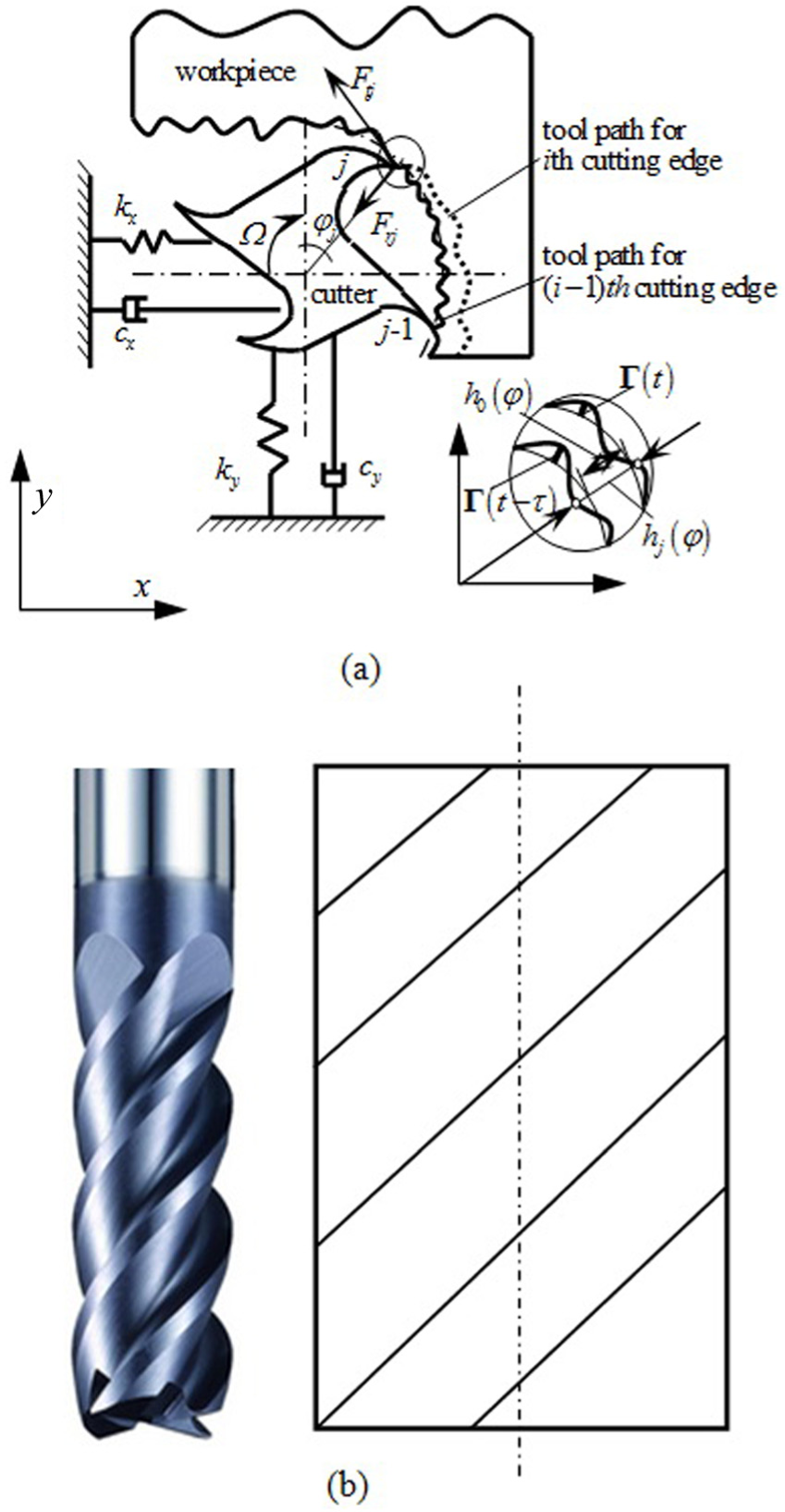
(a) Schematic diagram of dynamic milling system and (b) the simple end cutter with developed diagram of the cutter edge about the cutter axis.
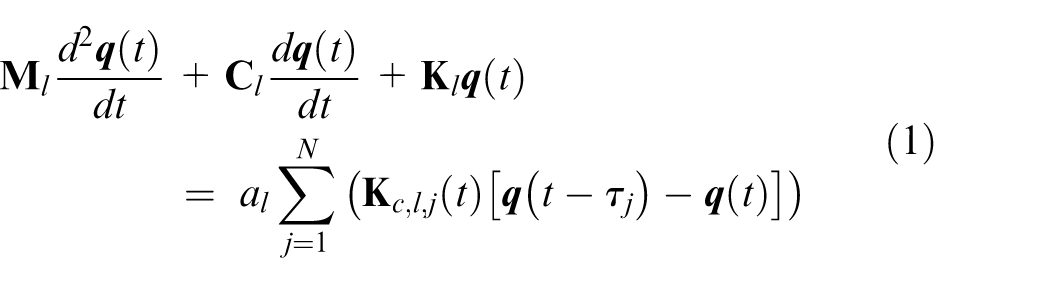
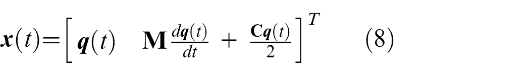
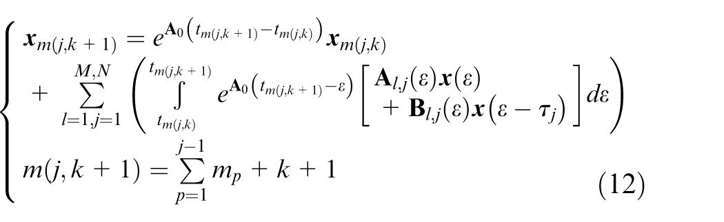
Figure 1(a) stands for the dynamic behavior of the milling process for a cutter with zero degree of cutter helix angle. However, for the simple cutter in Figure 1(b), the schematic diagram in Figure 1(a) cannot stand for the dynamic milling system again. Therefore, the cutter should be divided into a series of cutting elements along the cutter axis, and then every cutting element can be taken as a small cutter with zero cutter helix angle. In other words, the dynamic behavior of every cutting element can be represented using Figure 1(a). Therefore, for lth cutting element, the mathematical model of dynamic milling system can be expressed using the equation in our previous work 43
In this equation,
where M is the amount of the cutting elements included by the cutter;
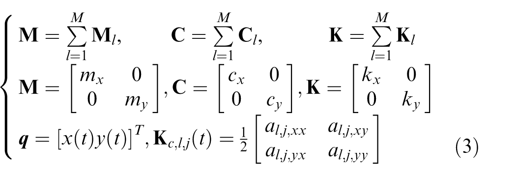
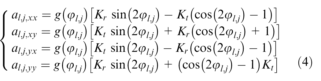
Kt and Kr are the static average cutting force coefficients along the tangent and radial direction of the cutter, respectively; (mx, my), (cx, cy) and (kx, ky) are the elements along x and y direction for the matrixes
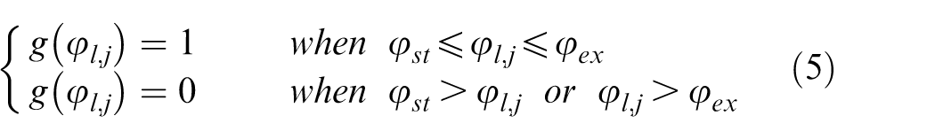
where

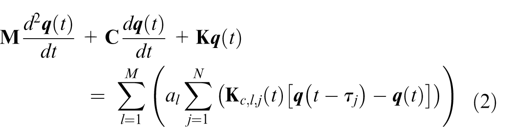
When equation (2) is obtained, the simple cutter’s dynamic behavior with non-zero helix angle can be studied. Therefore, the computation of equation (2) becomes a key for studying the stability lobes of a common cutter with non-zero helix angle.
Integral interpolation method
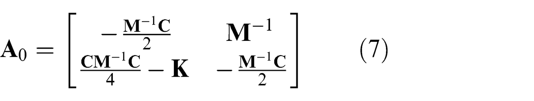
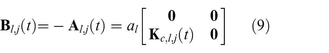
In order to predict the stability lobes, we introduce a new way using integral interpolation method; this method provides a new ideology combining the advantages of the integration and interpolation theories. First, we should simplify equation (2) using the following equation
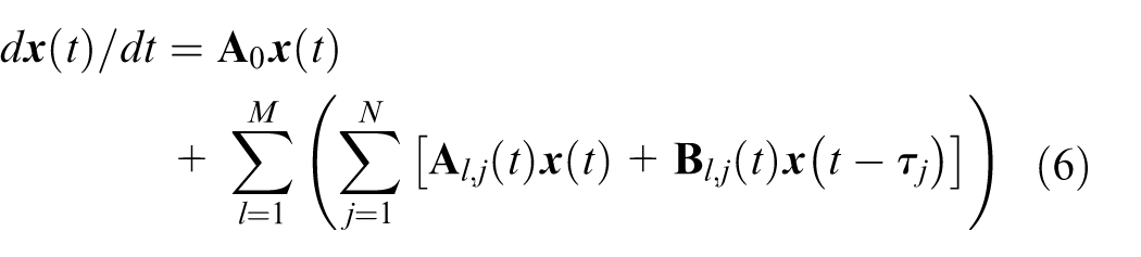
where the constant matrix
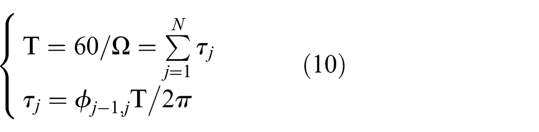
The spindle rotational speed is Ω. Then, the rotational period T of the spindle can be obtained. Each cutter edge’s period can also be computed using
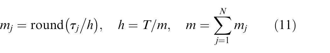
where h is time span for the time intervals round() stands for the rounding operation, such as round(4.2) = 4 and round(3.6) = 4.
For every time interval in the spindle period, the solution of equation (6) can be expressed using special formula. Here, taking the kth time interval in the jth cutter edge’s period as an example, this formula can be evaluated using
With ϵ ∈ [tm(j,k), tm(j,k + 1)],
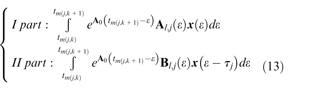
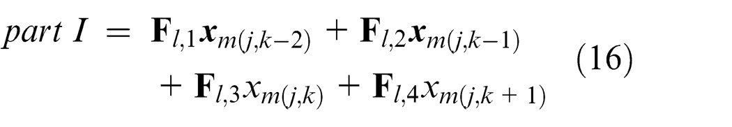
The first part can be simplified utilizing the interpolation method and the second part can be simplified using integration theory. It must be point out that part II can be taken as part I, and then part I is changed into part II.
And here, for the first part, we use the third-order Lagrange or Newton interpolation method, if using the Lagrange method. Here,
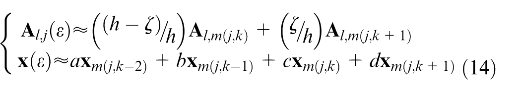
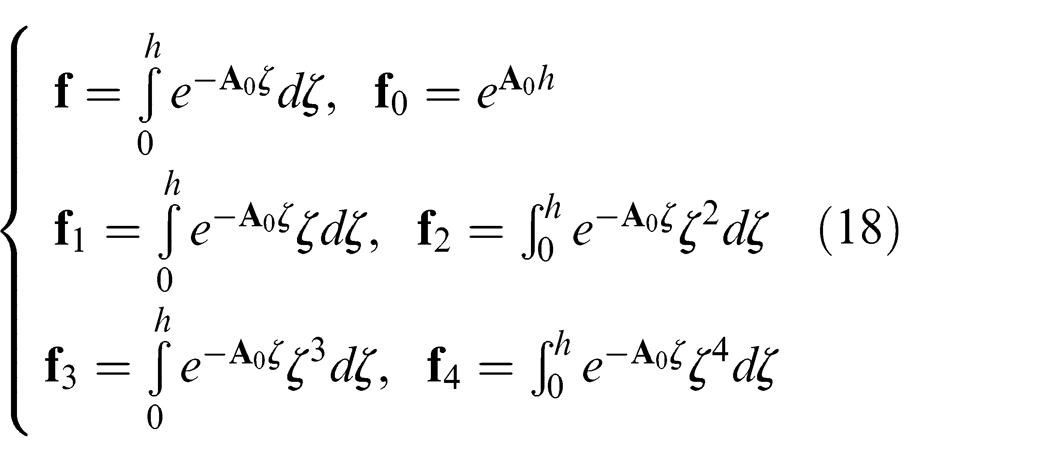
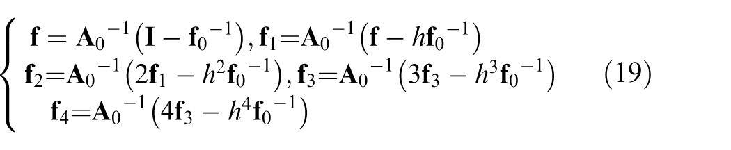
With ζ ∈ [0, h],
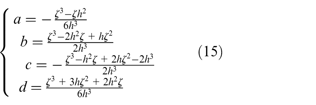
And
Thus, the first part in equation (13) can be calculated using the following analytical expressions
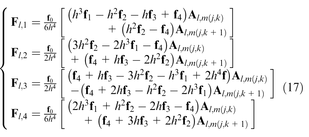
where
And
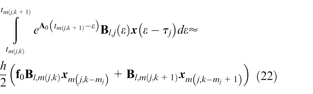
For the second part, the numerical integration method is used in this article, two-point integration method is adopted to simplify this part. And the simplification equation can evaluated utilizing the formula with
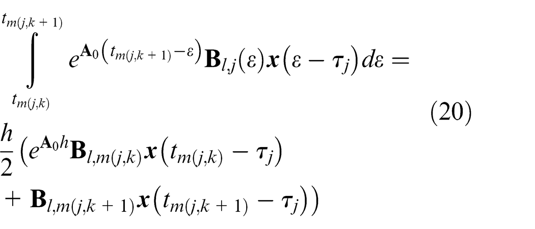
Then, for the reason of the periodic function of the
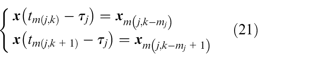
Therefore, equation (20) can be expressed in another way, which is
Finally, equation (12) can be evaluated using following equation after simplification of part I and part II with formulas from equations (14) to (22)
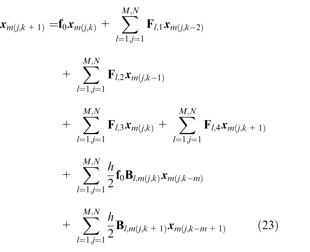
Then, equation (23) can be expressed after merging the same items with the formula
With
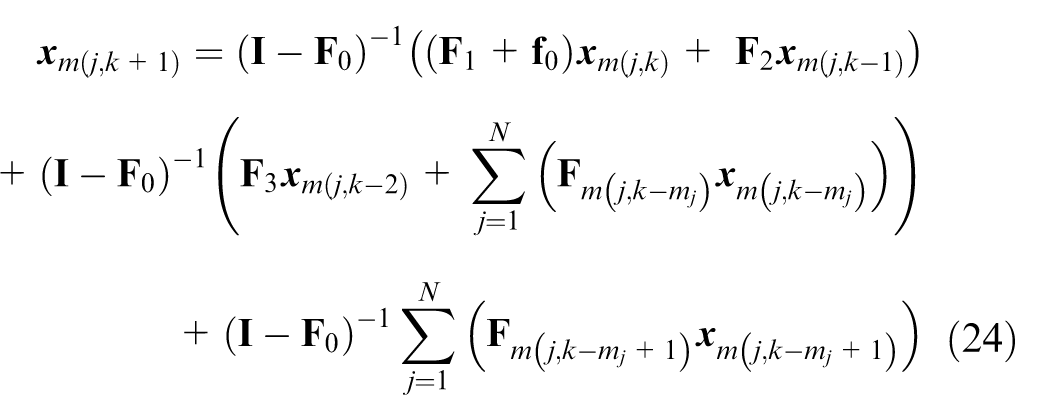
Then, equation (24) named as iterated function can be expressed in matrix form
In this equation, the column vector
The matrix
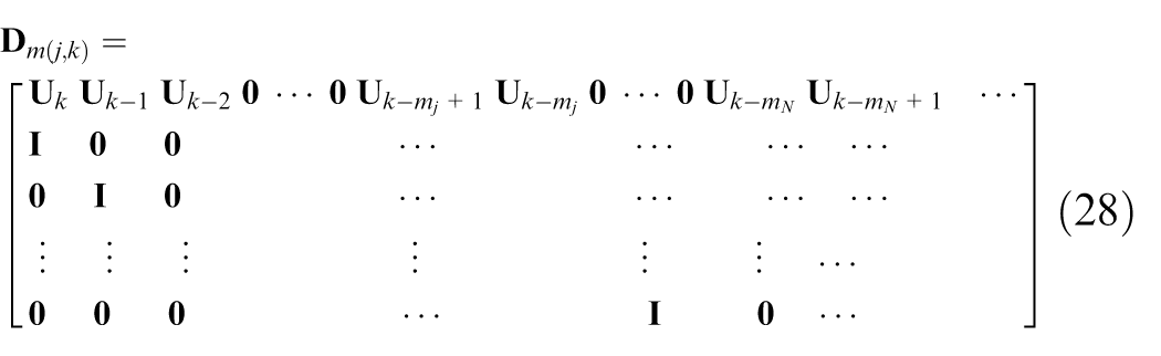
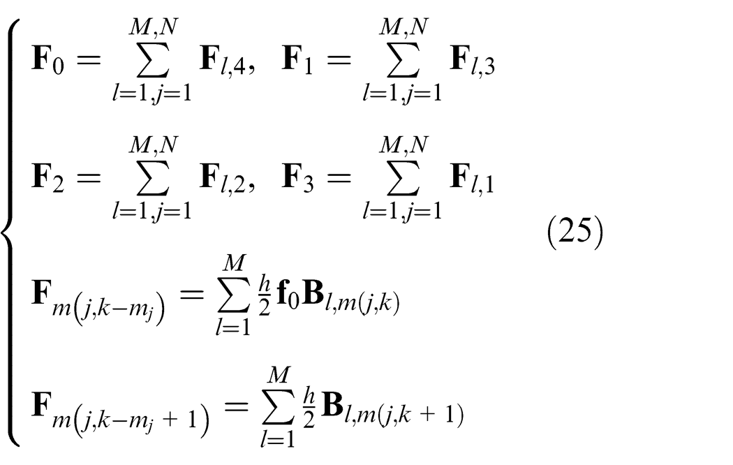
The parameters in above equation can be calculated utilizing following formulas
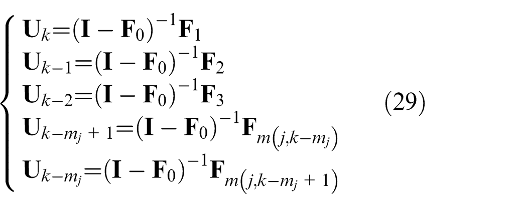
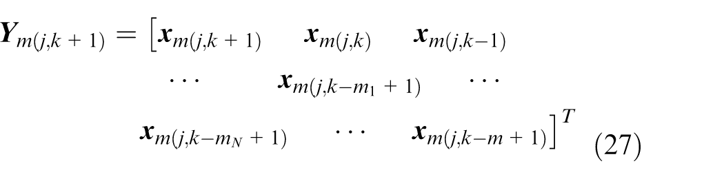
After iterated function (28) is known, the column vector

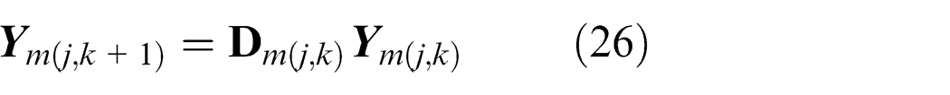
A new matrix

Thus, using the above transition function and Floquet theory, the stability lobes with multiple delays can be calculated.
Convergence property of the integral interpolation method
As an important factor which influences the computation time and efficiency, the convergence of the critical eigenvalues should be studied. Here, the 1-degree-of-freedom (DOF) down-milling process is chosen and the parameters of the dynamic machining system are
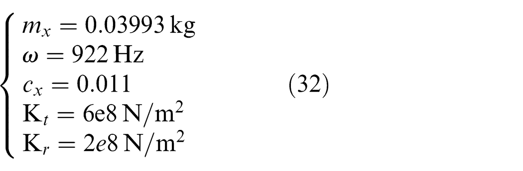
The cutter has two cutter edges. Figure 2 shows the relationship between the modulus of the critical eigenvalues |u| and the number m of the time intervals. Four groups of the machining parameters in Figure 2 are chosen as follows: A: {0.5, 4 mm, 9130 r/min}, B: {0.5, 5 mm, 4980 r/min}, C: {0.5, 6 mm, 2965 r/min}, D: {0.5, 7 mm, 2380 r/min}. The first parameter for these groups is the ratio between radial cutting depth and the cutter’s diameter, the second one is the axial cutting depth and the last one is the rotational speed of the cutter about the spindle.
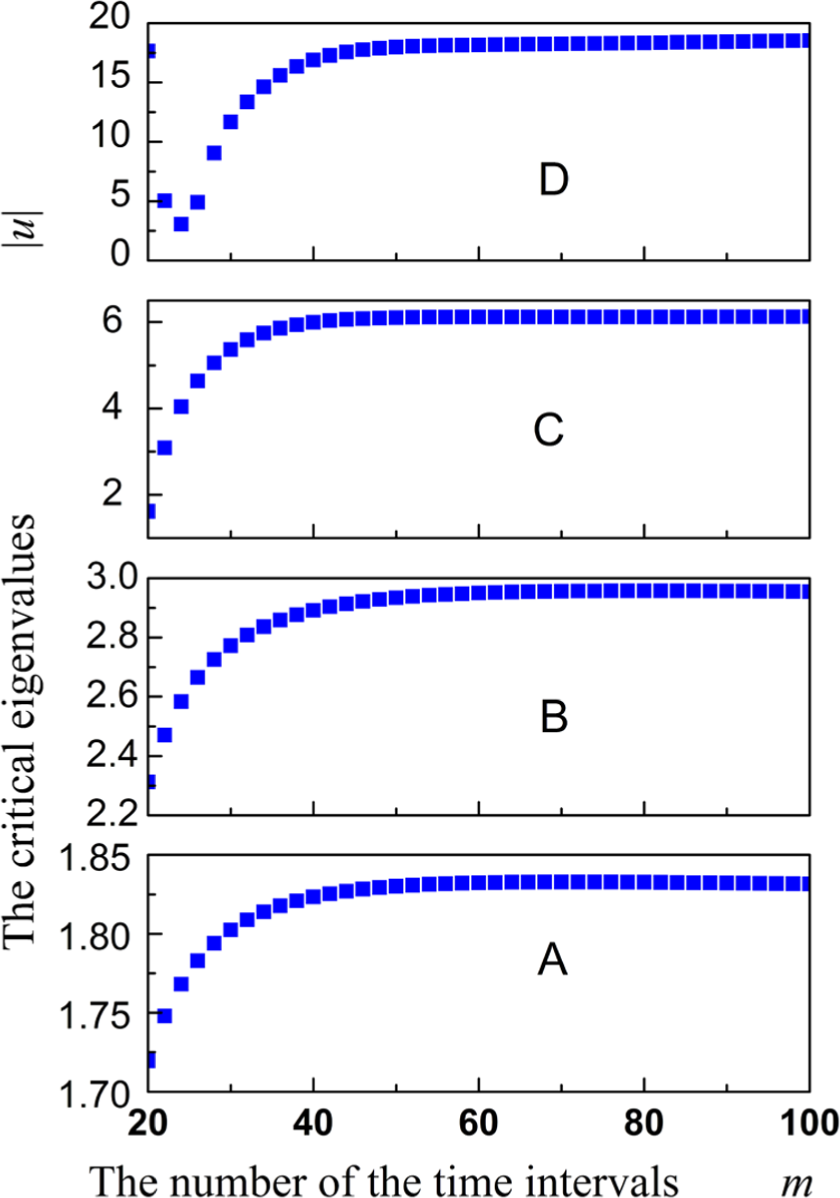
Convergence property of the method presented in this article.
For these examples, the convergence of the critical eigenvalues |u| for presented method in this article can be observed in Figure 2. The critical eigenvalue |u| is taken as the function of the time intervals number m. The plots show that how the critical eigenvalues |u| converge to a fix value. The difference ratios between the critical eigenvalues |u| when m = 40 and m = 60 are 0.004848 for A, 0.02011 for B, 0.01407 for C and 0.074796 for D.
Model and method verification
Stability lobes prediction for uniform pitch cutter with zero helix angle
The validity of the method presented in this article is verified using the experiment data in the literature. 27 The 2-DOF dynamic milling system is chosen and the properties of the system machined by the cutter which contains three cutter edges are illustrated in Table 1, half-immersion (up-milling) case are chosen.
Parameters of the dynamic system.
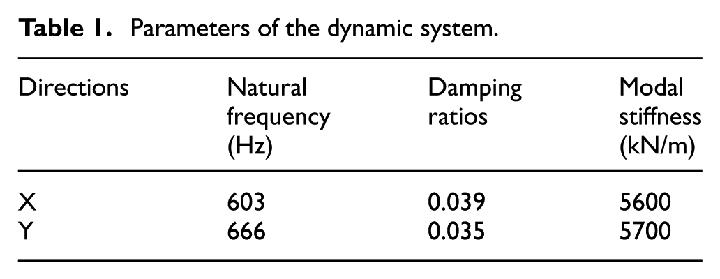
The cutting force coefficients are Kt = 600 MPa, Kr = 42 MPa. The experiment result expressed in the literature 27 and the predicting stability lobe utilizing the proposed method are illustrated in Figure 3. This stability limit lobe predicted by the presented method agrees well with that presented in the literature.
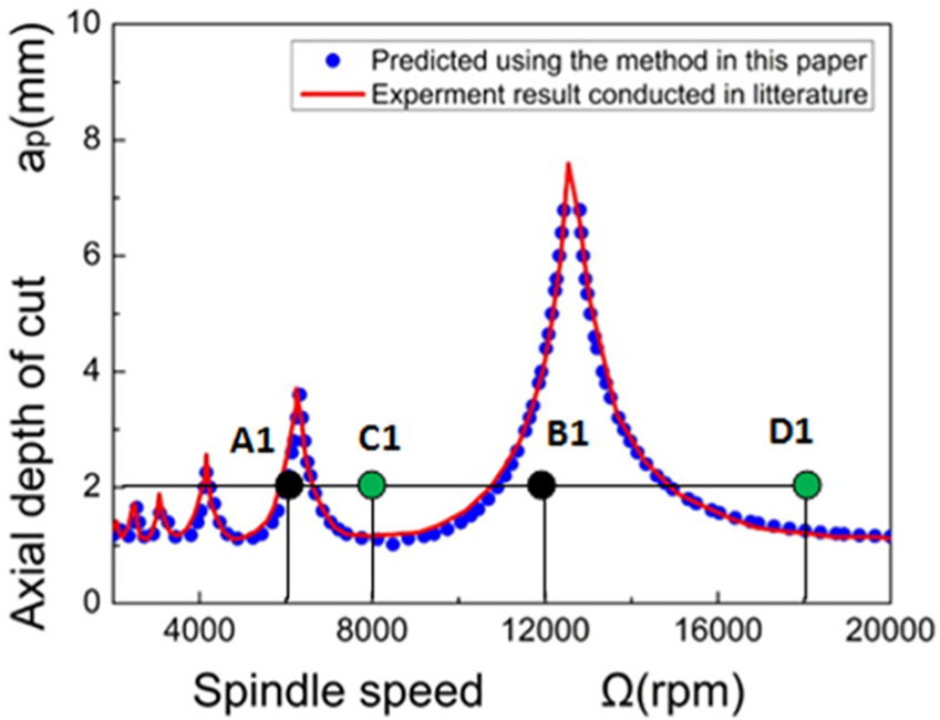
Comparison of the method in this article and that in the literature. 28
And, four points containing
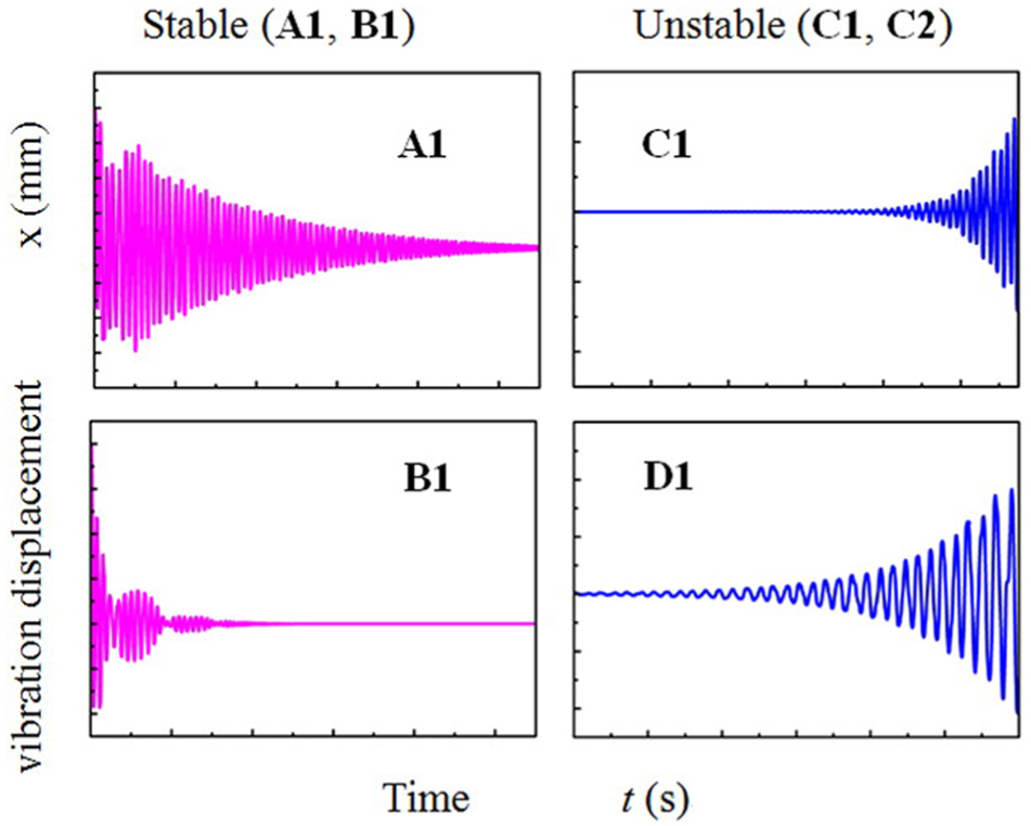
Simulation of vibration displacement in x-axis direction.
Stability lobes prediction for variable pitch cutter with zero helix angle
The dynamic system with variable pitch angle cutter can suppress the self-excited vibration and improve the limit of the dynamic system. The dynamic system in Altintas et al.’s 23 paper is used to verify the validity of the proposed method in this article. The parameters of the dynamic system are illustrated in Table 2.
Parameters of the dynamic system.
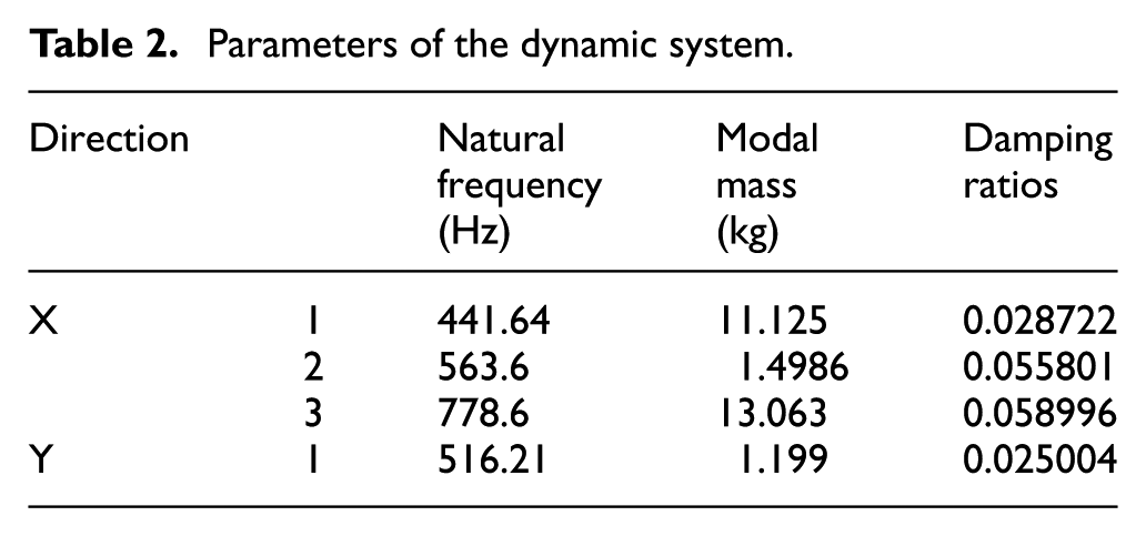
The ratio between radial cutting depth and cutter diameter is 0.5, the pitch angle of cutter is 70°-110°-70°-110°, the number of cutter edge is N = 4, the radius of the cutter is R = 9.525 mm, and the cutting force coefficients are Kt = 679 MPa and Kr = 249.193 MPa. Then the stability lobes are predicted using the Altintas’ method and the proposed method. The computational results are shown in Figure 5.
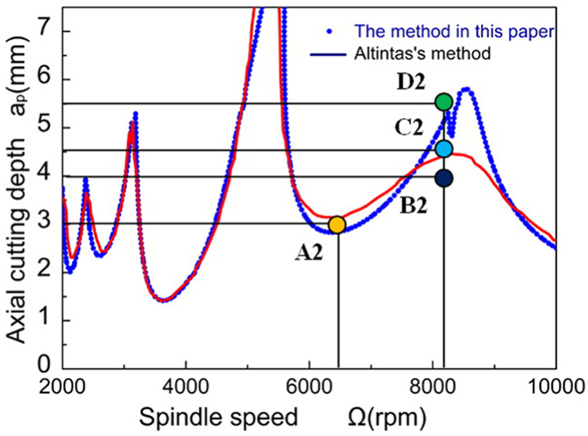
Comparison of the stability lobes predicted by literatures’ method and the proposed method.
Four points {
The vibration displacements are simulated and illustrated in Figure 6. It can be seen that the displacements for points
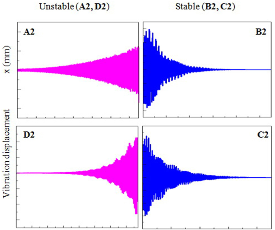
Simulation of vibration displacement in x-axis direction for the points in Figure 5.
Uniform pitch cutter with non-zero helix angle
In order to verify the validity of the presented modal, a system with the non-zero helix angle in Wan et al.’s 49 literature is chosen. The end mill with three cutting edge, helix angle of 30° and the diameter of 16 mm are selected to mill the aluminum alloy 7050. The parameters of the dynamic system are shown in Table 3.
Parameters of the dynamic system.
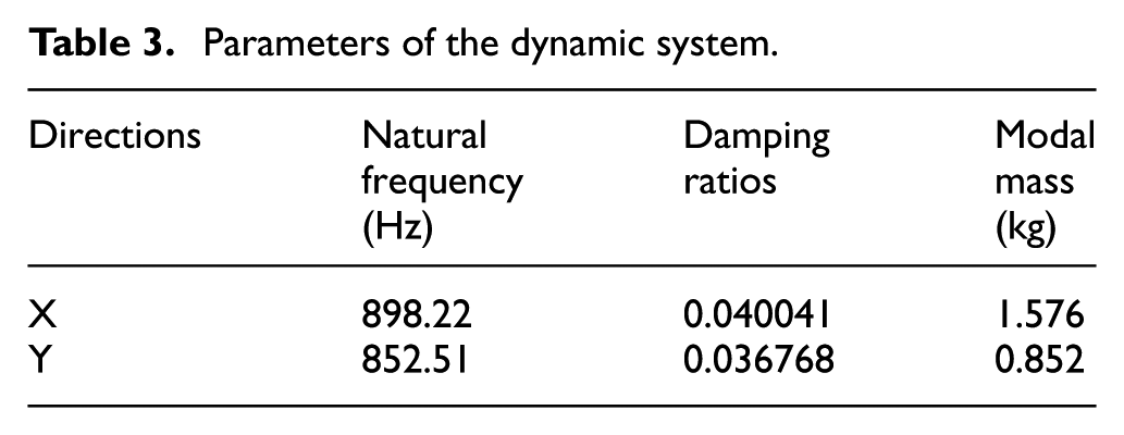
The cutting force coefficients along tangent and radial direction are as follows: Kt = 1209.355 MPa, Kr = 501.095 MPa. Down-milling process is conducted, and the radial cutting depth is 5 mm. The axial cutting depth is divided into 60 small elements along the cutting axis. Then, the stability lobe using the model is predicted by the method in this article, and this stability lobe is compared with that in Wan et al.’s 49 paper. The results are verified in his paper by experiments and shown in Figure 7, it can be seen that the stability lobe predicted using the model in this article is consist with stability lobes predicted by Wan. Therefore, the model in this article is valid for the cutter with the non-zero helix angle.
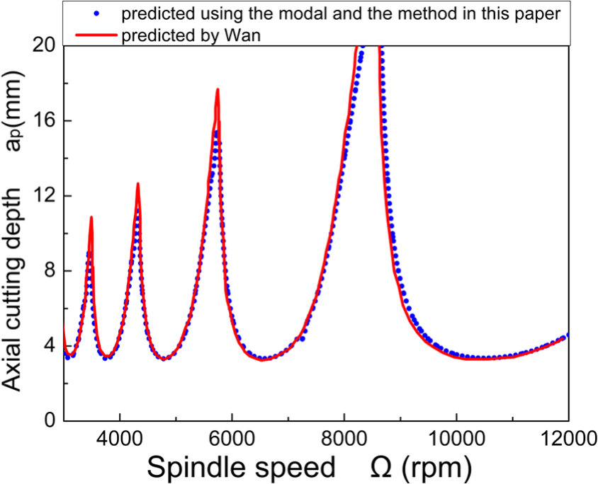
Stability lobes of the dynamic system with the cutter: helix angle of 30°, three cutting edge and the diameter of 16 mm.
Experimental verification
An experiment is conducted using thin-wall part which is taken as 1-DOF dynamic system, for the reason that the stiffness in thickness direction is more smaller than that in the other directions. The parameters of the dynamic system can be seen in Table 4.
Parameters of the dynamic system.
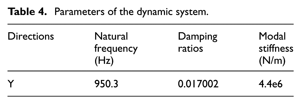
The diameter of the cutter is 12 mm, the helix angle of the cutter is 45°, the cutting force coefficients are Kt = 1625e6 MPa and Kr = 533e6 MPa, and the ratio between radial cutting depth and cutter diameter is 0.02. Down-milling process is adopted.
The results are shown in Figure 8. In this experiment, the parameter combinations of spindle speed and axial cutting depth are given as (2500 r/min, 6 mm), (2500 r/min, 12 mm), (3250 r/min, 6 mm), (3250 r/min, 12 mm), (4000 r/min, 6 mm), (4000 r/min, 12 mm), (4750 r/min, 6 mm) and (4750 r/min, 12 mm). The experimental results prove that the process parameters under the stability limit curve, namely (4750 r/min, 6 mm) and (4750 r/min, 12 mm), are stable, and the parameter combinations over the stability limit curve, namely (2500 r/min, 6 mm), (2500 r/min, 12 mm), (3250 r/min, 12 m), (4000 r/min, 6 mm) and (4000 r/min,12 m), are also unstable in real machining. The point (3250 r/min, 6 mm) is stable, whereas this point is above the stability lobes. The reason for this may be this point is too close to the stability curve and these points that close to the curve are influenced by the environment more easily. These show that the proposed method is of valid and effective.
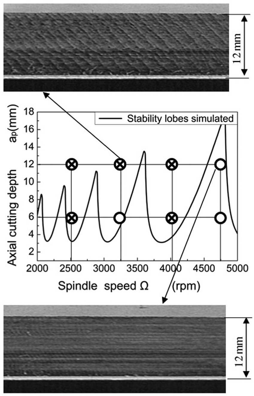
Experimental verification of the mode.
Parameters’ effect on the stability lobes
Utilizing the modal in this article, the parameters such as up or down-milling, helix angle and radial cutting depth’s effect on the stability lobes are studied. Here, the classical example using the variable pitch angle {70°-110°-70°-110°} cutter in section “Stability lobes prediction for variable pitch cutter with zero helix angle” is taken as the example to analyze the effect of these parameters on the stability lobes.
Up-milling and down-milling
In this section, the effect of up- or down-milling’s effect on the stability lobes is studied using some parameters. And three group parameters concluding the cutter’s helix angle β and the ratio between the radial cutting depth and the cutter diameter aD are chosen, these parameters are (a) {β = 45°, aD = 0.4}, (b) {β = 30°, aD = 0.6} and (c): {β = 0°, aD = 0.5}. Then, three graphs are plotted using these three group parameters in Figure 9(a)–(c).
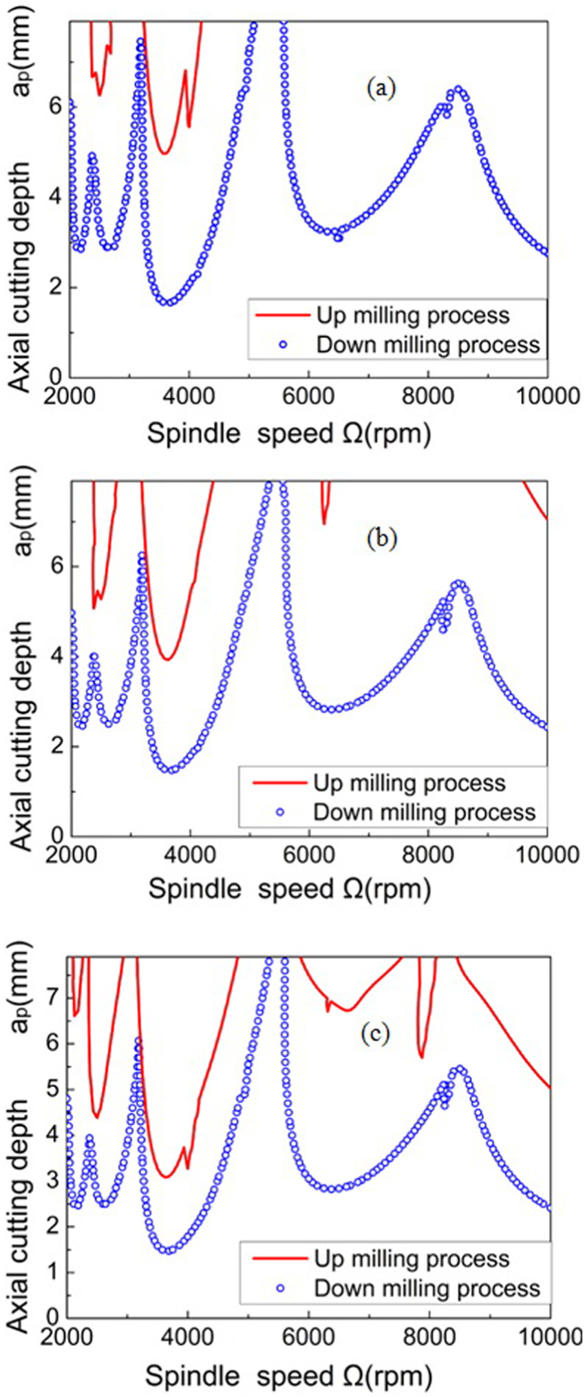
Up- or down-milling’s effect on the stability lobes: (a) helix angle is 45°, aD = 0.4; (b) helix angle is 30°, aD = 0.6 and (c) helix angle is 0°, aD = 0.5.
Some phenomenon can be found in Figure 9; they are as follows:
Different milling direction (up- or down-milling) has great influence on the stability lobes. For all the lobes in (a), (b) or (c) of Figure 9, the stability lobes are different from each other.
Up-milling process is more helpful for the dynamic system’s stability. For all figures in (a), (b) and (c) of Figure 9, the stability lobes of up-milling process are higher than that of the down-milling process.
The cutting force for the cutter edge of up-milling process changes from zero to maximum during the machining process, whereas the cutting force for the cutter edge of down-milling process changes from maximum to zero. Therefore, up-milling process has smaller impact on the machining system compared with down-milling process for the above two reasons. Therefore, up-milling process has smaller effect on the machining system compared with down-milling process. This is probably the reason why up-milling process is more helpful for keeping the system stable.
Helix angle
Three group parameters are chosen as: aD = 0.1 with β = 0°, 30°, 45° and 60°; aD = 0.5 with β = 0°, 30°, 45° and 60° and aD = 0.9 with β = 0°, 30°, 45° and 60°. Then, the stability lobes with these parameters are predicted using the model and the method in this article. And these stability lobes’ curves are illustrated in Figure 10.
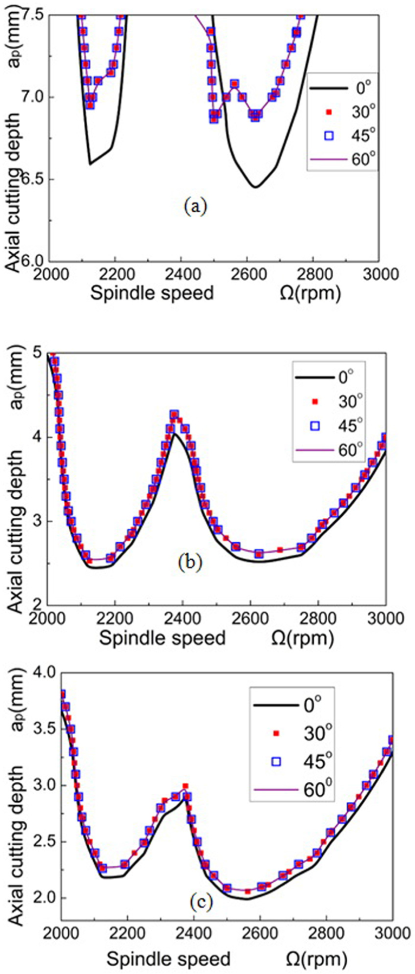
Influence of the helix angle on the stability lobes: (a) aD = 0.1, β = 0°, 30°, 45° and 60°; (b) aD = 0.5, β = 0°, 30°, 45° and 60° and (c) aD = 0.9, β = 0°, 30°, 45° and 60°.
The first phenomenon in Figure 10 is that the helix angle has effect on the stability lobes, and the possible reason for this maybe the helix angle induces the change of the instantaneous uncut chip thickness for ith cutter edge, whereas when helix angle is 0, the instantaneous uncut chip thickness is fixed for ith cutter edge.
The second phenomenon can be found that when helix angle is larger than 0° and smaller than 30°, helix angle has obvious influence on the stability of the dynamic system. However, when helix angle is larger than 30°, the helix angle’s effect on the stability lobe is small. The third phenomenon is that the larger of the aD, the smaller effect of the helix angle on the stability lobes.
Radial cutting depth
In this section, different cutting depths are chosen to analyze the effect of the axial cutting depth on the stability lobes. Here, the parameters are chosen as follows: aD = 0.5, β = 30°; aD = 0.6, β = 30°; aD = 0.7, β = 30°; aD = 0.8, β = 30°; aD = 0.9, β = 30° and aD = 1.0, β = 30°. Then, the stability lobes are predicted using the presented method and illustrated using three-dimensional picture in Figure 11.
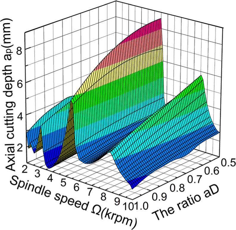
Effect of the radial cutting depth on the stability lobes.
It can be found that as the radial cutting depth increases, the limit of axial cutting depth decreases at the same spindle rotational speed. As the radial cutting depth increases, the cutting forces increase, and the cutting force coefficients change simultaneously. This may be the reason for the decrease of the axial cutting depth limit as the increase of radial cutting depth.
In order to investigate the radial cutting depth’s influences on the axial cutting depth limit, the relationship curves between the radial cutting depths given as form of aD from 0.5 to 0.9 and the axial cutting depth limit at different spindle speeds are studied. These curves are illustrated in Figure 12. From this figure, a truth can be found that the relationship between axial cutting depth limit and aD cannot be expressed by a line. The reason for this may be that when radial cutting depth increases, the cutting forces and the cutting force coefficients change nonlinearly.

Relationship between radial cutting depth and the axial cutting depth.
Conclusion
A mathematical model of the dynamic system combining the effect of the cutter helix angle is deduced in this article, and then, a new integral interpolation method using this model to predict the stability lobe is introduced. Subsequently, the properties of this method are analyzed. And three examples are used to verify the validity. Utilizing the method, some key parameters’ effects on the stability lobes are analyzed. Finally, the following conclusions can be obtained:
The model of the dynamic system in this article can combine the effect of the cutter’s helix angle. The cutter is divided into a series of cutting elements along the cuter axis. Each cutting element in machining process is taken as a dynamic system; then combining all the elements’ control equation, the model of the cutter’s dynamic system can be obtained.
The prediction method of stability lobes in this article can be used in the dynamic system with the multi-regenerative chatter. This article takes the multi-regenerative chatter as a focus to study, the mathematical model which can be used for the multi-regenerative delays is built.
The influence of the helix angle on the stability of the dynamic system is studied. A phenomenon can be found in the example that when the helix angle is larger than 0 and smaller than the 30°, the effect of the helix angle on the stability of the dynamic system is obvious. However, when the helix angle is larger than 30°, the helix angle has little influence on the stability of the dynamic system.
The milling direction of the machining process has great effect on the stability lobes. Especially, the up-milling process is more helpful for keeping the system stable.
The three-dimensional stability lobes are computed for special cutting condition. It can be found that as the radial cutting depth increases, the limit of axial cutting depth decreases at the same spindle rotational speed.
Footnotes
Appendix 1
Declaration of conflicting interests
The author(s) declared no potential conflicts of interest with respect to the research, authorship, and/or publication of this article.
Funding
The author(s) disclosed receipt of the following financial support for the research, authorship, and/or publication of this article: This research is supported by NSFC (Nos 51475148, 51205112 and 11405044), Foundation of He’nan Education Committee (No. 15A460025) and by Doctoral Fund of Henan Polytechnic University (No. B2014-034)