
Abstract
Variation in the geometric and surface features of segmented chips with an increase in the volume of material removed and tool wear has been investigated at cutting speeds of 150 and 220 m/min at which the cutting tools fail due to gradual flank wear and plastic deformation of the cutting edge, respectively. Among the investigated geometric variables of the segmented chips, slipping angle, undeformed surface length, segment spacing, degree of segmentation and chip width showed the different variation trends with an increase in the volume of material removed or flank wear width, and achieved different values when tool failed at different cutting speeds. However, the chip geometric ratio showed a similar variation trend with an increase in the volume of material removed and flank wear width, and achieved the similar value at the end of tool lives at cutting speeds of both 150 and 220 m/min regardless of the different tool failure modes. Plastic deformation of the tool cutting edge results in severe damage on the machined surface of the chip and significant compression deformation on the undeformed surface of the chip.
Keywords
Introduction
The segmented chip (as shown in Figure 1) is the typical chip produced when machining titanium alloys;1–3 its geometric features include segment spacing (L), depth of saw-tooth (
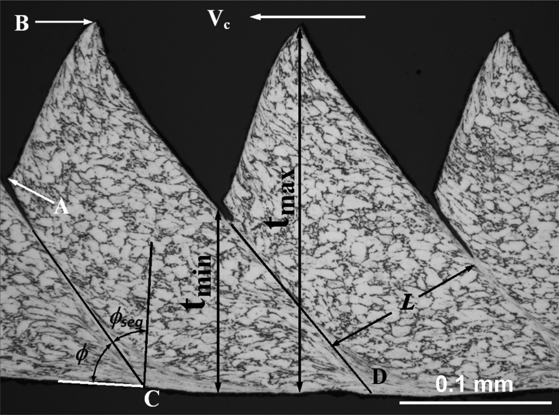
Geometrical features of segmented chip made by machining of Ti-6Al-4V alloy at a cutting speed of 150 m/min.
The effect of cutting speed on the chip geometry depends on a number of process parameters including the range of cutting speeds. Segment spacing,6,11 degree of segmentation (segmentation index)7,11 and the chip roughness ratio10,12 increase with cutting speed during the transition from irregular to regular segmented chips and reach their constant values at a critical cutting speed,
In addition to cutting speed, feed and tool geometry also play an important role in the geometry of the segmented chip. 8 Chip geometry can be changed dramatically from segmented to continuous chip by an increase in workpiece temperature before it enters the primary shear zone by laser beam preheating the workpiece locally in front of cutting tool during laser-assisted machining. 6 The effect of high temperature of workpiece before it enters the primary shear zone due to preheating by external heat source is different from the effect of the high temperature at the cutting zone due to high cutting speed; the former changes the deformation behaviour during chip formation. 6
The geometric features of the segmented chip are also found to be affected by an increase in the volume of material removed at a cutting speed of 150 m/min at which tool failure is characterized by gradual flank wear, 4 which is one of the dominant tool failure modes attributed to dissolution–diffusion, abrasion and attrition mechanisms.15,16 Diffusion results in surface weakening and embrittlement of the cutting edge of tool due to loss of carbon17,18 and the pulling out and removing of tungsten carbide (WC) particles from tool surface due to loss of cobalt. 19 WC particles pulled out from the tool surface remain at the interface between tool’s flank face and newly machined surface of the workpiece and the interface between tool’s rake face and the newly machined surface of the chip, which causes tool wear by abrasion and attrition. Changes in chip geometric variables are associated with the change in tool geometry and an increase in cutting temperature with an increase in the volume of material removed. 20 With an increase in cutting speed to 220 m/min, the cutting tool failed due to excessive maximum flank wear as a result of plastic deformation of the cutting edge due to the high cutting temperatures and high pressure at the cutting edge. 21 The changes in chip geometric features due to plastic deformation of the cutting edge are found to be different from those due to gradual flank wear and are presented in this research.
Materials and experimental procedures
The workpiece material used in this study is the Ti-6Al-4V alloy; its chemical composition, microstructure and hardness can be found elsewhere.4,21
A tungsten carbide (WC–Co) insert containing 3 wt% cobalt was used in this study, and its mechanical and thermal properties are listed in Table 1. The rake angle of the insert was +15° and the entry angle was 45°. With the inclination of −6° in the tool holder, the effective rake angle for this study was +9°. The optical image of cross section and cutting edge surface observed by scanning electron microscopy (SEM) of the as-received insert is shown in Figure 2.
Mechanical and thermal properties of the WC–Co cutting insert used in this study.
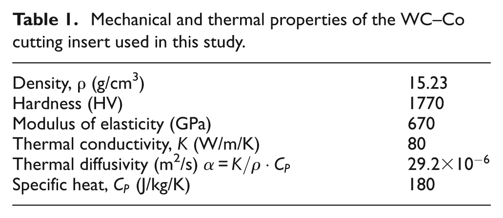
(a) Optical image of cross section and (b) SEM image of cutting edge of the as-received cutting insert for this study. 21
The cutting insert with entry angle of 45° was chosen for straight turning to produce a 45° chamfer, on which a laser beam can radiate for preheating of the workpiece in front of cutting tool for authors’ previous research on laser-assisted machining.6,22–24 The authors kept using this insert for this study in order to compare the geometric features of the segmented chip made by conventional machining with those of the chips made by laser-assisted machining.
Straight turning was conducted under dry cutting condition at cutting speeds of 150 and 220 m/min with a constant depth of cut of 1 mm and feed of 0.28 mm because of the distinctive tool failure modes observed at these two cutting speeds. 21 The cutting was interrupted and the chip was collected in every 5.2 cm3 of material removed in order to investigate the effect of the development of tool wear on the change in chip geometry. The geometric variables investigated in this study are illustrated in Figure 1.
As described in the authors’ previous publications,3,4,6,12 the collected chips were cut into short segments with a length of about 3 mm and then mounted with epoxy in such a way that they have been erected on their longitudinal edges in order to make the cross section after polishing straight across its length as shown in Figure 1. The geometric variables were measured from the cross section of polished chips, and the results listed in this study are the average of 50 measurements for each chip geometric variable. The polished chips were etched with Kroll’s reagent to reveal the geometric features and microstructures of the chips. SEM was used to observe the free surface and machined surface of the chips collected with the different volumes of material being removed. Change in chemical composition on the chip surfaces was identified with X-ray energy dispersive spectroscopy (EDS).
Chip temperature at the cutting zone was measured by an infra-red camera (FLIR A40) during cutting in order to characterize variation of chip temperature with tool wear. The emissivity of the workpiece alloy was obtained through the following two steps: 12 (1) a workpiece alloy sample was spot-welded with thermocouples and heated in a furnace up to the target temperature without surface oxidation, and (2) the appropriate emissivity of the workpiece alloy was selected to ensure the temperature of the heated workpiece measured from the infra-red signal agrees with that measured by the thermocouples.
Results and discussion
Tool failure modes
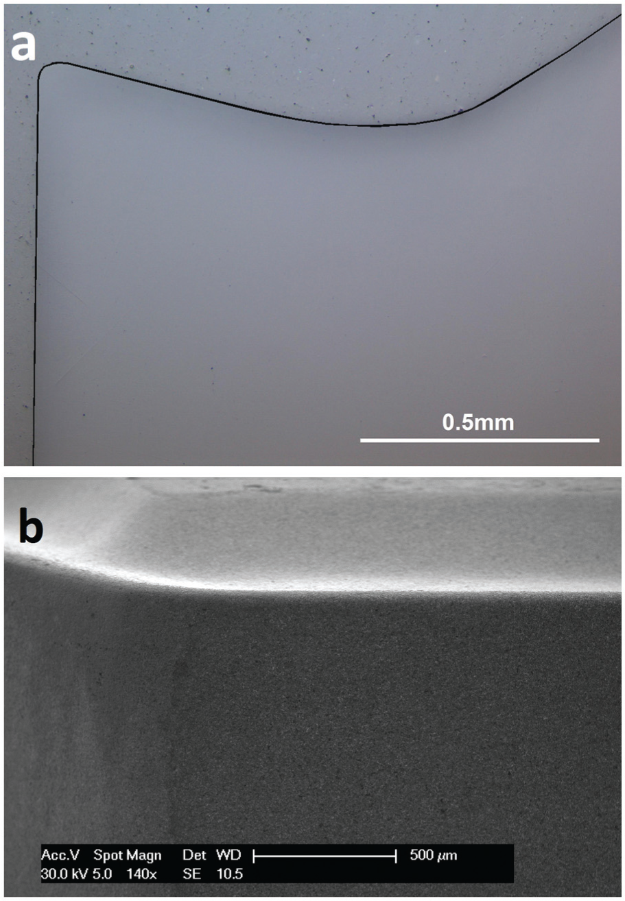
Flank wear, crater wear, plastic deformation of cutting edge, chipping and notching are found to be the principal tool failure modes when machining titanium alloys with carbide tools.15,17,25,26 Flank wear is the typical gradual tool failure mode at low cutting speed, and plastic deformation of cutting edge is a catastrophic tool failure mode at high cutting speed. 21 The cross sections and surfaces of cutting edges after tool failure with 57.2 and 20.8 cm3 of material being removed at cutting speeds of 150 and 220 m/min, respectively, are shown in Figure 3. Significant amount of material is lost from the tool’s rake face at a cutting speed of 150 m/min (Figure 3(a)), whereas the cutting edge is significantly pushed upwards as a result of plastic deformation at a cutting speed of 220 m/min (Figure 3(b)).
(a, b) Optical images of cross sections and (c, d) SEM images of surfaces of cutting tool edges after the tool failed at cutting speeds of (a, c) 150 m/min and (b, d) 220 m/min.20,21 The broken lines in (a) and (b) are the profile of the cutting edge of the as-received cutting insert extracted from Figure 2(a).
The evolutions of flank wear and chip temperature with an increase in volume of material removed are shown in Figure 4. Rapid growth of flank wear width with volume of material removed at a cutting speed of 220 m/min is attributed to the plastic deformation of cutting edge due to oversized chip built-up edge at the tool’s nose corner 21 as marked by an arrow in Figure 3(d), whereas the flank wear gradually increases with an increase in volume of material removed up to 46.8 cm3 at a cutting speed of 150 m/min.
Evolution of (a) flank wear width and (b) maximum chip temperature with an increase in volume of material removed at cutting speeds of 150 and 220 m/min. 21
The maximum chip temperature was found to increase with an increase in the volume of material removed as shown in Figure 4(b); the rate that the maximum chip temperature increased with the volume of material removed at a cutting speed of 220 m/min was much higher than that at a cutting speed of 150 m/min.
Variation of the cross-sectional geometry of the segmented chip
Effect of volume of material removed
The cross sections of the chips produced at the beginning of the cut (the volume of material removed is between 0 and 5.2 cm3) and at the end of tool life (the volume of material removed is between 15.6 and 20.8 cm3 for a cutting speed of 220 m/min and between 52.0 and 57.2 cm3 for a cutting speed of 150 m/min) at cutting speeds of 220 and 150 m/min are shown in Figure 5. It was observed that the chip morphology changed with an increase in volume of material removed, and the change in chip geometry is different at different cutting speeds as summarized in Figures 6 and 7. The change in chip formation is the result of an increase in the cutting temperature (as indicated by the increase in the maximum chip temperature as shown in Figure 4(b)) and the progressive change of the tool geometry due to tool wear. 27
Cross-sectional images of chips made at cutting speeds of (a, b) 220 m/min and (c, d) 150 m/min after removing the volume of material (a, c) between 0 and 5.2 cm3, (b) between 15.6 and 20.8 cm3 and (d) between 52.0 and 57.2 cm3.
Variation of slipping angle in the segmented chips with volume of material removed at cutting speeds of 150 and 220 m/min. Error bars show ±1 standard deviation.
Variation of (a) segment spacing, (b) chip geometric ratio, (c) degree of segmentation, (d) length of undeformed surface and (e) chip width of the segmented chips with the volume of material removed at cutting speeds of 150 and 220 m/min.
There is no observable difference in deformation in the segmented chips (as shown in Figure 5(a) and (c)) and chip geometric features (as shown in Figures 6 and 7 for slipping angle, chip geometric ratio, degree of segmentation and segment spacing) when the volume of material removed is between 0 and 5.2 cm3 at cutting speeds of 150 and 220 m/min, which agrees with the previous conclusion that the size and spacing of the segments are independent of the cutting speed3,8,28 within the cutting speed range of
However, significant shear deformation was found on the undeformed surface and machined surface in the chips made at the end of tool life with a total volume of material removed reaching 20.8 cm3 at a cutting speed of 220 m/min (marked by A and C in Figure 5(b)) and only on the machined surface of the chip obtained at the end of tool life with a total volume of material of 57.2 cm3 being removed at a cutting speed of 150 m/min (marked by C in Figure 5(d)). This indicates that severe friction occurred between tool’s flank face and workpiece and between the tool’s rake face and the flowing chip when the tool reached its life at a cutting speed of 220 m/min and only between the tool’s rake face and the flowing chip when the tool reached its life at a cutting speed of 150 m/min.
In addition to the change in deformation during chip segmentation with an increase in volume of material removed, significant changes in slipping angle and geometric features of the chips made at cutting speeds of 150 and 220 m/min occurred with an increase in volume of material removed as shown in Figures 6 and 7. The slipping angle started to gradually decrease with an increase in the volume of material removed when the total volume of material removed was greater than 26.0 cm3 and reached 48.6° at the end of tool life after the total volume of material removed was 57.2 cm3 at a cutting speed of 150 m/min. Furthermore, the standard deviation of the slipping angle did not change with an increase in volume of material removed at a cutting speed of 150m/min.
At a cutting speed of 220 m/min, the slipping angle started to increase with an increase in the volume of material removed when the total volume of material removed was greater than 10.4 cm3 and reached 65.5° at the end of tool life after the total volume of material removed was 20.8 cm3 (as shown in Figure 6). The segments became more irregular since the standard deviation of the slipping angle increased from 2.7° after the volume of material being removed was 5.2 cm3 to 4.3° after the total volume of material being removed was 20.8 cm3. This indicated a dramatic change in tool cutting edge due to the plastic deformation as shown in Figure 3(b).
The effect of volume of material removed on segment spacing, undeformed surface length, degree of segmentation and geometric ratio of the segmented chip and chip width is shown in Figure 7. At a cutting speed of 150 m/min, the segment spacing, undeformed surface length, degree of segmentation and geometric ratio were 114 µm, 132 µm, 0.46 and 0.84, respectively, at a volume of material removed of 5.2 cm3 and started to decrease with an increase in the total volume of material removed of 5.2, 5.2, 5.2 and 26.0 cm3, respectively, and reached their minimum values of 82 µm, 100 µm, 0.39 and 0.79, respectively, at the total volume of material removed of 36.4 cm3 following which all the four geometric variables increased with the volume of material removed. The segment spacing, undeformed surface length, degree of segmentation and geometric ratio were 91 µm, 119 µm, 0.45 and 0.95, respectively, when the tool reached its life with the total volume of material of 57.2 cm3 being removed.
The segment spacing, undeformed surface length, degree of segmentation and geometric ratio of the chip made at a cutting speed of 220 m/min with the volume of material removed between 0 and 5.2 cm3 were 111 µm, 130 µm, 0.46 and 0.83, respectively, which are almost identical to those of the chips made at a cutting speed of 150 m/min at the same volume of material removed between 0 and 5.2 cm3. However, the segment spacing, undeformed surface length and the degree of segmentation decreased, and the chip geometric ratio increased with an increase in the volume of material removed up to the end of tool life. At the end of tool life (the total volume of material removed was 20.8 cm3), the segment spacing, undeformed surface length, degree of segmentation and geometric ratio are 82 µm, 100 µm, 0.37 and 0.94, respectively.
The chip width at a cutting speed of 150 m/min increased slightly with the volume of material removed (as shown in Figure 7(e)) because the edge of the chip became rough (formation of a burr on the chip edge) and increased thermal expansion of the cutting tool edge due to the higher cutting temperature with an increase in total volume of material removed (evolution of tool wear) as shown in Figure 4(b). The rough edge of the chip is produced because the cutting edge became blunt as a result of tool wear and the chip built-up edge, 21 which can make the workpiece surface rough. However, the chip width dramatically reduced when the total volume of material removed was greater than 10.4 cm3 at a cutting speed of 220 m/min because of the severe plastic deformation of the cutting edge. 21 The effective depth of cut was reduced, which made the finishing diameter of the workpiece larger than the pre-set diameter because of the reduction in chip width. This proves that the surface finish and/or dimensional accuracy may deteriorate due to excessive tool wear.
Effect of flank wear
Figure 8 shows the maximum chip temperature and geometric variables measured in Figures 4(b) and 7 plotted against the average flank wear width measured in Figure 4(a) in order to investigate the effect of flank wear on chip formation.
Effect of flank wear width on (a) maximum chip temperature, (b) segment spacing, (c) chip geometric ratio, (d) degree of segmentation and (e) length of undeformed surface of the segmented chips with tool failure modes of gradual flank wear at a cutting speed of 150 m/min and plastic deformation of the cutting edge at a cutting speed of 220 m/min.
The maximum chip temperature increased with an increase in flank wear width at cutting speeds of both 150 and 220 m/min as shown in Figure 8(a); the difference in the maximum chip temperature between the two cutting speeds was diminished with an increase in flank wear width. This indicates that the chip temperature strongly depends on the tool wear.
The segmented spacing, degree of segmentation and undeformed surface length showed clear two-stage variation with minimum values achieved at flank wear width of 0.185 mm when the tool failed due to the gradual flank wear mode at a cutting speed of 150 m/min, whereas these geometric variables gradually decreased with an increase in flank wear width when plastic deformation of cutting edge dominated tool failure at a cutting speed of 220 m/min.
It should be noted that the geometric variables of segmented spacing, degree of segmentation and undeformed surface length reached the different values at the end of tool lives when the tool failed with these two different failure modes.
Some geometric features such as segmented spacing and size are strongly dependent on rake angle of cutting insert. 8 The two-stage variation of the geometric variables at a cutting speed of 150 m/min is attributed to the variation of rake angle of cutting insert during cutting. 4 Rake angle increased at early stage of gradual flank wear because of the effect of chip built-up edge 29 and loss of material on the tool rake face; 21 the minimum values of the segmented spacing, degree of segmentation and undeformed surface length were achieved when the rake angle reached its maximum value (about 18.7°) at the flank wear width of 0.185 mm.
The continuous reduction in segmented spacing, degree of segmentation and undeformed surface length at a cutting speed of 220 m/min is attributed to the continuous increase in rake angle; the maximum rake angle (about 19.2°) was achieved at the end of tool life because the cutting edge was pushed upwards due to plastic deformation as shown in Figure 3(b).
However, variation of chip geometric ratio with flank wear width shows a single trend for both tool failure modes (Figure 8(b)). The chip geometric ratio did not change significantly when the average flank wear width is below 0.20 mm, and it was the greater than 0.94 when the average flank wear width reached its limit of tool life criterion (0.3 mm) for both tool failure modes.
It has been clearly shown that the chip geometric ratio is the only geometric variable that can characterize the tool failure regardless of its failure mechanisms (plastic deformation of cutting edge and gradual flank wear at cutting speeds of 220 and 150 m/min, respectively) because the chip geometric ratio increases with an increase in the local temperature of workpiece before it enters the cutting zone. This agrees with the observation during laser-assisted machining where workpiece material is heated locally by a laser beam in front of cutting tool. 6 The tool reaches its life due to either plastic deformation of the cutting edge or gradual flank wear when the chip geometric ratio is greater than 0.94 probably because the local temperature of workpiece before it enters the cutting zone is higher than a limit as the result of an increase in cutting temperature due to an increase in tool wear20,27 as shown in Figures 4(b) and 8(a).
SEM observation of surfaces of the segmented chips
Free surface of the segmented chips
The free surface of a typical segmented chip shows lamellar characteristics as shown in Figure 9. Each segment consists of two surfaces: an undeformed surface (A) and slipping surface (B) whose cross sections correspond to line marked with A and B, respectively, in Figure 5. The undeformed surface was produced by the flank face of the cutting tool when the chip was separated from the workpiece in the previous revolution of cut, while the slipping face of the chip was produced during the segmentation in the current revolution of the cut.
Undeformed surfaces (A) and slipping surfaces (B) on the free surface of segmented chip made at a cutting speed of 220 m/min with (a) a new tool with the volume of material removed between 0 and 5.2 cm3 and (b) worn tool with the volume of material removed between 15.6 and 20.8 cm3.
There is no observable difference on the free surface of the chips made at a volume of material removed between 0 and 5.2 cm3 at a cutting speed of 220 m/min as shown in Figure 10(a) and (b) compared with the free surface of the chips made at the same volume of material removed at a cutting speed of 150 m/min, 4 which can be explained by the fact that the chip segmentation is caused by the same mechanism at the two cutting speeds because of the very small differences in chip temperature (≈30 °C as shown in Figures 4(b) and 8(a)) 12 and flank wear width (<10 µm as shown in Figure 4(a)) during the initial short cuts at these two cutting speeds. The slipping surface is dominated by plastic deformation dimples and the undeformed surface consists of sliding lines and a row of elongated dimples (marked by an arrow in Figure 9(b)) because the chip was removed from workpiece through the growth of voids in the previous revolution at the location of the dimples. 4
SEM photographs of (a, c) slipping surfaces and (b, d) undeformed surfaces of segmented chips made at a cutting speed of 220 m/min. (a) and (b) are from the volume of material removed between 0 and 5.2 cm3 and (c) and (d) are from the volume of material removed between 15.6 and 20.8 cm3.
At the end of tool life with the volume of material removed between 15.6 and 20.8 cm3 at a cutting speed of 220 m/min, the deformation on the slipping surface (Figure 10(c)) showed the similar viscous behaviour with that observed on the slipping surfaces of the chips made by laser-assisted machining with a new tool 6 and dry machining with a worn tool at the end of tool life when the volume of material removed was between 52.0 and 57.2 cm3 at a cutting speed of 150 m/min; 4 this is because the local temperature of workpiece is significantly high before it entered the cutting zone and segmentation as shown in Figures 4(b) and 8(a).
The undeformed surface of the chips made with a volume of material removed between 15.6 and 20.8 cm3 at cutting speed of 220 m/min showed a significant folding effect in the cutting direction as shown in Figure 10(d), which proves that significant compressive deformation occurred on the undeformed surface during segmentation. Unlike the chips made by the worn tool at the end of its life at a cutting speed of 150 m/min, there are no plastic deformation dimples found on the undeformed surface of the chips made by the worn tool at the end of its life at a cutting speed of 220 m/min because of the different tool failure mechanisms. 4
Machined surface of the chip
Similar to the observations associated with the chips made by a new tool with the volume of material removed between 0 and 5.2 cm3 at a cutting speed of 150 m/min, 4 the machined surface of the chips made by a new tool with the volume of material removed between 0 and 5.2 cm3 at a cutting speed of 220 m/min showed periodically distributed sliding regions and slipping regions (marked with C and D, respectively, in Figure 11(a) and (b)) along the length of chip. The sliding region showed sliding lines which were produced due to the friction of the flowing chip over the tool’s rake face. The surface on the slipping zone between two sliding zones was characterized by plastic deformation dimples.
SEM photographs of the machined surface of chips made at cutting speed of 220 m/min. (a) and (b) are from the volume of material removed between 0 and 5.2 cm3 and (c) and (d) are from the volume of material removed between 15.6 and 20.8 cm3.
A significant amount of dark areas were observed inside the dimples in the slipping regions on the machined surfaces of the chips made with a volume of material removed between 0 and 5.2 cm3 (Figure 11(b)). These areas were identified as rich in carbon by EDS elementary analysis and is due to deposition of TiC layer removed from the tool’s rake face during segmentation. 4
With an increase in the total volume of material removed up to 20.8 cm3 at which the cutting tool reached its life at a cutting speed of 220 m/min as the result plastic deformation of cutting edge, 21 a dramatic change was observed on the machined surface of the chips. The middle region of the machined surface showed significant damage with severe scratches (as shown in Figure 11(c) and (d)), which is believed to be produced due to friction as the chip moved over the plastically deformed cutting edge. A significant amount of particles were observed in the scratch region (as identified by an arrow in Figure 11(d)), and these particles were identified as WC as shown in Figure 12; they were removed from the cutting tool by the flowing chip. The detached WC particles may result in more material lost from the rake face wear due to the severe attrition wear caused by these abrasive WC particles. 15
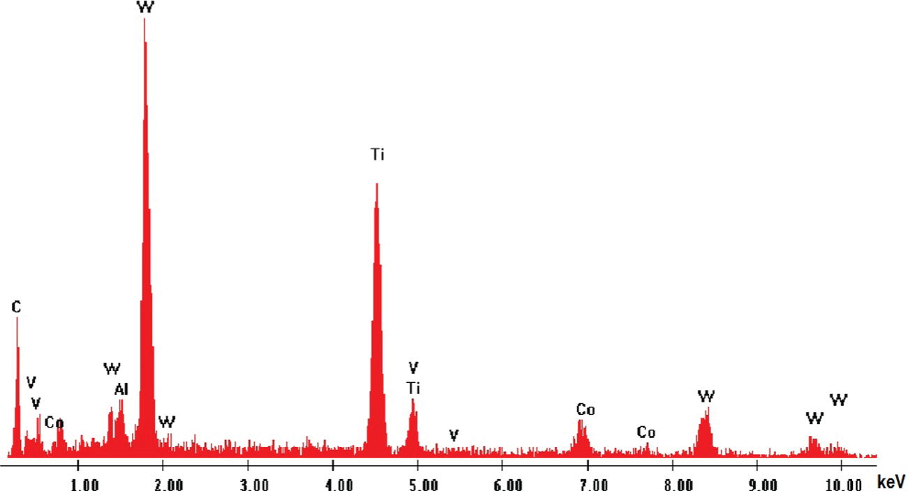
EDS spectra for particles in Figure 11(d).
Conclusion
The geometric and surface features of segmented chips produced by a new tool are the same for a low total volume of material removed at the two cutting speeds of 150 and 220 m/min investigated here.
Variations in the chip geometric variables including slipping angle, undeformed surface length, segment spacing, degree of segmentation and chip width with an increase in volume of material removed are different when the cutting speeds range between 150 and 220 m/min due to the different tool failure modes at these cutting speeds.
The undeformed surface length, segment spacing, and degree of segmentation show two-stage variation with an increase in average flank wear width at a cutting speed of 150 m/min at which the tool fails due to gradual flank wear, whereas these geometric variables gradually decrease with an increase in average flank wear width at a cutting speed of 220 m/min at which the tool fails as a result of plastic deformation of the cutting edge. The values of undeformed surface length, segment spacing and degree of segmentation at the end of tool lives are different at the different cutting speeds.
Chip geometric ratio varies with an increase in the volume of material removed or flank wear width in the similar trend at both cutting speeds of 150 and 220 m/min. The chip geometric ratio increases to above 0.94 when the tool reaches its life due to either plastic deformation of the cutting edge at a cutting speed of 220 m/min or gradual recession of the cutting edge at a cutting speed of 150 m/min.
The difference in the segmented chip made by a worn tool at the end of its life at a cutting speed of 220 m/min compared with segmented chips made by a worn tool at the end of its life at a cutting speed of 150 m/min is that the undeformed surface of the chip shows significant compression deformation and the machined surface of the chip shows a region with severe damage in which a significant amount of WC particles are observed because of the plastic deformation of the cutting edge.
Footnotes
Acknowledgements
The authors acknowledge the facilities, and the scientific and technical assistance, of the Australian Microscopy & Microanalysis Research Facility at the RMIT Microscopy & Microanalysis Facility, RMIT University.
Declaration of conflicting interests
The author(s) declared no potential conflicts of interest with respect to the research, authorship and/or publication of this article.
Funding
This work was supported by the Defence Materials Technology Centre (DMTC) and the Queensland Centre for Advanced Materials Processing and Manufacturing. The DMTC was established and is supported under the Australian Government’s Defence Future Capability Technology Centres Programme.