
Abstract
Variation of cutting forces has been investigated and correlated with the development of tool wear during dry machining of Ti-6Al-4V alloy at cutting speeds of 150 and 220 m/min, respectively. Both the average and maximum flank wear increased more significantly with volume of material removed at higher cutting speed. The tool failure mode is flank wear at both cutting speeds; however, the mechanisms for the excessive flank wear are different. The average width of flank wear reaches the criterion at cutting speed of 150 m/min after 57.2 cm3 of material has been removed as a result of the gradual recession of cutting edge due to crater wear, which led to significant rise of feed force only at the end of tool life. Both average width and maximum width of flank wear exceeds the criteria at cutting speed of 220 m/min after 20.8 cm3 of material has been removed because of severe plastic deformation of cutting edge at the nose radius, which resulted in dramatic increase in all three components of cutting forces at the end of tool life. The cutting edge at the nose radius was pushed up from the flank face in the chip flow direction due to the oversized built-up edge-induced compressive stress applied from the flank face.
Keywords
Introduction
With their unique mechanical, physical and chemical properties, such as high strength-to-weight ratio, ability to retain strength at high temperature and strong corrosion resistance, titanium alloys are in increasing applications in aerospace and chemical engineering industries.1,2 However, machining titanium alloys is a high-cost process because of the long machining time and short tool life, 3 which impacts the application of titanium alloys. The cutting speed allowed to machine Ti-6Al-4V alloy with reasonable tool life is about 30 and 60 m/min by using high-speed steel (HSS) tools and cemented tungsten carbide tools, respectively, 2 which is much lower than that allowed to machine aluminum alloys; this is mainly due to the unique characteristics of titanium alloys.
The low thermal conductivity of titanium alloys (7.3 W/m/K for Ti-6Al-4V alloy) results in the large proportion of the heat generated during the machining processes being conducted into the cutting tool rather than being carried away by the discarded chip. 4 Hence, the cutting temperature is significantly high, and dramatically increases with increasing cutting speed. 5 Another reason for the poor machinability of titanium alloys is the small tool-chip contact area on the tool’s rake face, which consequently leads to high stress at the cutting edge. 4
Performance of a cutting tool during machining titanium alloys depends on the mechanical, physical and chemical properties of the tool material at high temperature and high pressure.6,7 It has been proven that the straight tungsten carbide (WC/Co) tools are the most suitable cutting tools for machining titanium alloys because of their high hardness at high temperature, good thermal conductivity, toughness and cost effectiveness.4,8
Straight tungsten carbide tools generally contain a small amount of cobalt (Co) as binder to bond carbide particles together to sustain the high cutting pressure. Flank wear, crater wear, chipping and notching as common tool failure modes have been reported when machining titanium alloys with carbide tools due to the mechanisms of dissolution–diffusion, adhesion, abrasion and attrition.3,4,9 –12
Tool material is gradually lost from its flank face and rake face due to flank and crater wear. Flank wear is believed to be due to abrasion wear between the newly generated work surface and flank face adjacent to the cutting edge, whereas the crater wear is the result of exchange (redistribution) of atoms (Co and C) across the tool-chip interface boundary by the dissolution–diffusion mechanism. 13 Carbon diffusion results in carbon deficiency in the subsurface region, which becomes brittle,4,14 whereas the cobalt diffusion leads to the pulling out and removing of WC particles, which is much more deleterious to the hardness and wear-resistance of cutting tool edge than the diffusion of tungsten and carbon.13,15 Therefore, the cobalt diffusion dominates the crater wear mechanism.
Both flank and crater wear are significantly accelerated with increase in cutting speed because of the significant softening of cutting tool material and increase in diffusion rate at the higher cutting temperature as a result of increase in cutting speed.16,17
Cutting forces are affected not only by cutting conditions such as cutting speed, feed, depth of cut, tool geometry and cooling conditions18 –27 but also by cutting time,20,28 –30 cutting distance 31 and tool wear. 21 Increase in volume of material removed with prolonged machining leads to increase in cutting forces because the geometry of cutting edge is altered as a result of built-up edge and tool material loss at the cutting edge. Good correlation between cutting forces and flank wear can be used to predict the tool life and monitor tool wear with the information of cutting forces.32 –36 However, crater wear may reduce cutting forces if the working rake angle increases at the early stage of machining.36,37 Hence, the variation of cutting forces with tool wear is dependent on the tool wear mode and is complicated.
In addition to tool wear, plastic deformation of cutting edge also occurs. Plastic deformation of the cutting edge in metal cutting is due to the high concentration of compressive stresses and temperature, both of which are localized at the small chip-tool contact area on the rake face. 38 Plastic deformation occurs when the cutting insert does not have sufficient flow strength to maintain its shape at high cutting temperature 39 and cutting speed. 40 Astakhov believes that plastic deformation of the cutting edge is the predominant cause of premature tool failure during high-speed cutting of hard-to-machine materials because it deteriorates the dimensional accuracy of the machined part. The plastic deformation of cutting tool is characterized as lowering of the cutting edge as a result of high-temperature creep 41 or depression of the rake face of the cutting tool. 42 Greater plastic deformation occurs in the Co phase resulting in the tearing-off of carbide grains. 41
Two mechanisms that contribute to the tool failure mode of flank wear, named as plastic deformation and recession of cutting edge, have been produced at different cutting speeds during dry turning of Ti-6Al-4V alloy in this study. The mechanisms and changes in tool geometry associated with these two types of tool wear are investigated, and the correlation of cutting forces with evolution of tool wear is presented for both types of tool failure.
Workpiece material, tool and experimental procedures
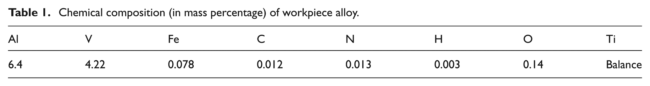
The workpiece material used in this study is Ti-6Al-4V alloy, and its chemical composition is listed in Table 1. The hardness of this workpiece tested at load of 500 gf was in the range of 312–340 Hv0.5 with an average of 325 Hv0.5.
Chemical composition (in mass percentage) of workpiece alloy.
The optical microstructure of the workpiece alloy after etching with Kroll’s reagent is shown in Figure 1. It contains primary alpha (α) phase (marked with A) with average size of 10.9 µm, granular beta (β) phase (marked with B) and α/β colony region (marked with C) with average sizes of 1.9 and 8.3 µm, respectively. The spacing of the lamellar structure in α/β colonies is about 1.3 µm.
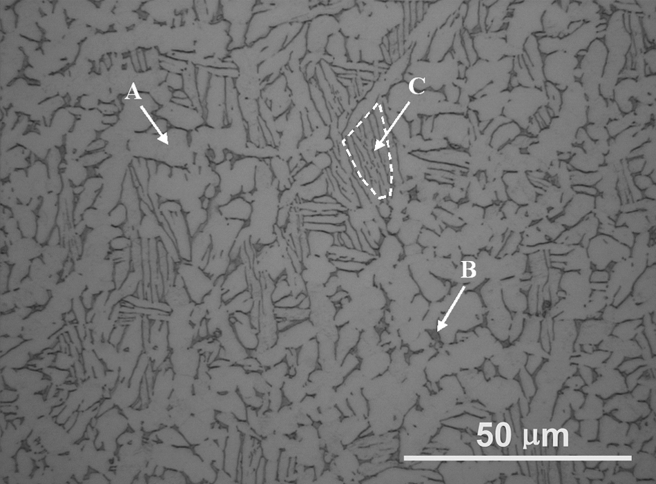
Optical microstructure of workpiece alloy used in the present study.
Turning was conducted with a carbide insert (CNMX1204A2-SMH13A) supplied by Sandvik. The rake angle of the insert was +15°, and the entry angle was 45°. With the inclination of −6° in the tool holder, the effective rake angle for this study was +9°.
Figure 2 shows the cross-sectional profile across the cutting edge, scanning electron microscopy (SEM) image and X-ray energy dispersive spectrum (EDS) of the as-received insert. The radius at the cutting edge is measured as 40 µm as shown in Figure 2(a), and the elements of tungsten (W), cobalt (Co), aluminum (Al) and oxygen (O) were found in the cutting insert by EDS elemental analysis as shown in Figure 2(c).
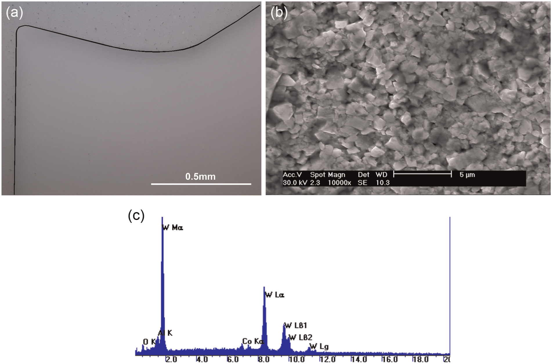
(a) Optical image of cross section of cutting insert, (b) SEM image and (c) EDS spectrum of the surface of cutting insert used for the present study.
During turning, cutting forces were recorded in X, Y and Z directions (as shown in Figure 3) with a three-component force sensor (PCB Model 260A01) to investigate the variation of cutting forces under different cutting conditions and the evolution of cutting forces with the tool wear. The cutting forces were calculated with the compensation of crosstalk between the three-component signals.
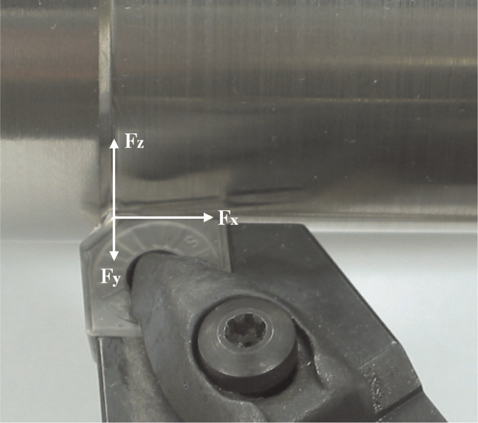
Image of setup of cutting tool and coordinating system for measuring the cutting forces.
Cutting was performed at cutting speeds of 150 and 220 m/min with the constant depth of cut of 1 mm and feed of 0.28 mm. The cutting speeds used in this research are much higher than the economic achievable cutting speed when uncoated carbide tool is used (around 60 m/min). The cutting was interrupted every 5.2 cm3 of material removed to investigate the development of tool wear and its effect on cutting forces.
The flank and rake faces of the worn tools were observed by using SEM to investigate the wear mechanisms, and EDS was used to identify the elemental changes on the tool’s faces as the result of tool wear.
Results
Development of tool wear
To accelerate tool wear during machining, a large feed of 0.28 mm was used in this experiment. The variation of average flank wear (VB) and the maximum flank wear (VBmax) with volume of material removed at cutting speeds of 150 and 220 m/min is shown in Figure 4. The measurement of flank wear followed ISO3685 standard, 43 as the width of the flank wear was measured from the position of the original major cutting edge in the cutting edge plane perpendicular to the major cutting edge as shown in Figure 5.
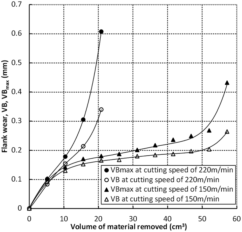
Variation of average flank wear (VB) and the maximum flank wear (VBmax) with volume of material removed at cutting speeds of 220 and 150 m/min.
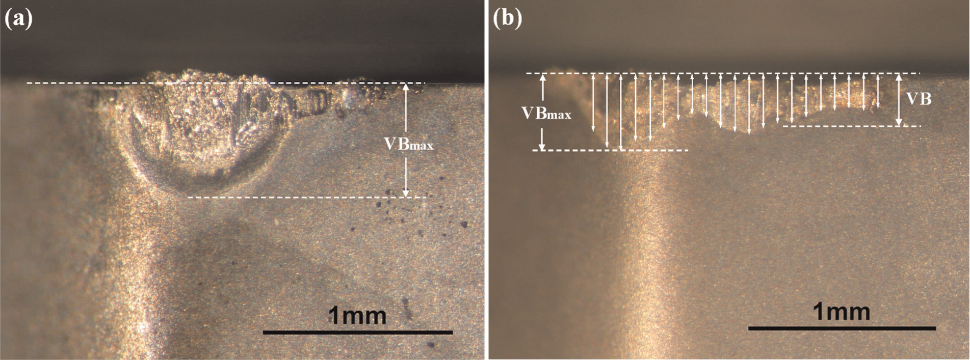
Images of flank faces of the cutting edges of tools after removing (a) 20.8 cm3 and (b) 57.2 cm3 of material at cutting speeds of 220 and 150 m/min, respectively.
Both the average and maximum flank wear increased dramatically and almost linearly with the volume of material removed at cutting speed of 220 m/min; however, they increased gradually, with the volume of material removed, from about 10.4 to 41.6 cm3 at cutting speed of 150 m/min, after the initial rapid increase with the volume of material removed from 0 to 10.4 cm3. Rapid increases in both the average and maximum flank wear occurred when the volume of material removed is greater than 46.8 cm3 at cutting speed of 150 m/min.
The flank faces of the tool’s cutting edges after 20.8 and 57.2 cm3 of material removed at cutting speeds of 220 and 150 m/min are shown in Figure 5. A large nose wear was found at the tool corner at cutting speed of 220 m/min, as shown in Figure 5(a), which is similar to the V-shaped non-uniform flank wear at the nose, 44 whereas tool material loss occurred across the cutting edge at cutting speed of 150 m/min (Figure 5(b)).
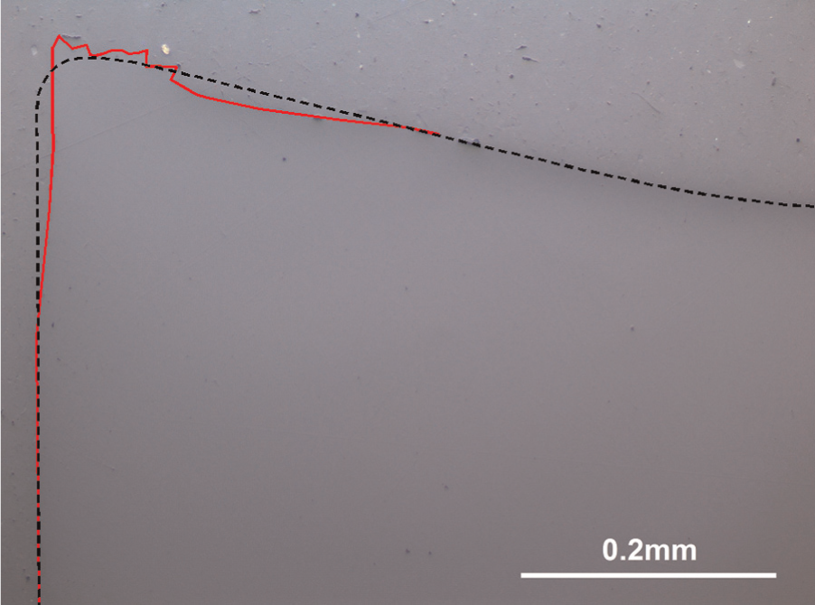
Figure 6 shows the cross sections of the cutting tool edges after 20.8 and 57.2 cm3 of material being removed at cutting speeds of 220 and 150 m/min. The broken curve is taken from Figure 2 and shows the outline of the cutting edge before cutting. It can be clearly seen that the cutting edge at cutting speed of 220 m/min after 20.8cm3 of material being removed was plastically deformed leading to the cutting edge being pushed up (as shown in Figure 6(a)). Significant tool material was removed from the tool’s rake face, which resulted in the cutting edge being much lower than its original outline at cutting speed of 150 m/min after 57.2cm3 of material being removed (see Figure 6(b)). The loss of tool material from the rake face is characterized by the depth of crater wear (KT) and recession of cutting edge (h) as marked in Figure 6(b).
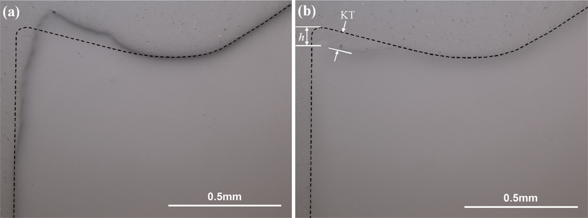
Cross sections of cutting tool edges after (a) 20.8 and (b) 57.2 cm3 of material being removed at cutting speeds of 220 and 150 m/min, respectively.
The change in the cutting edges due to plastic deformation and loss of material at cutting edge, as shown in Figure 6, resulted in the changes in cutting forces, which subsequently led to deterioration in both the surface finish and dimensional accuracy of the machined parts. Therefore, tool tests were stopped after 57.2 and 20.8 cm3 of material was removed at cutting speeds of 150 and 220 m/min, respectively, because the cutting tool was considered to reach its end of life because either the maximum or average flank was over or close to the criteria (average flank wear is over 0.3 mm or the maximum flank wear is over 0.6 mm) listed in the standard. 43 This shows again that increase in cutting speed changes the tool failure mode and dramatically reduces tool life.
Variation of cutting forces with tool wear
Cutting forces are found to vary with the extent of tool wear as shown in Figure 7. At the beginning of cut, the three components of the cutting force at cutting speed of 220 m/min are slightly lower than those at cutting speed of 150 m/min (the differences are about 16, 7 and 30 N for feed force, thrust force and the main cutting force, respectively), which could be the result of significant thermal softening due to the higher cutting temperature at higher cutting speed.
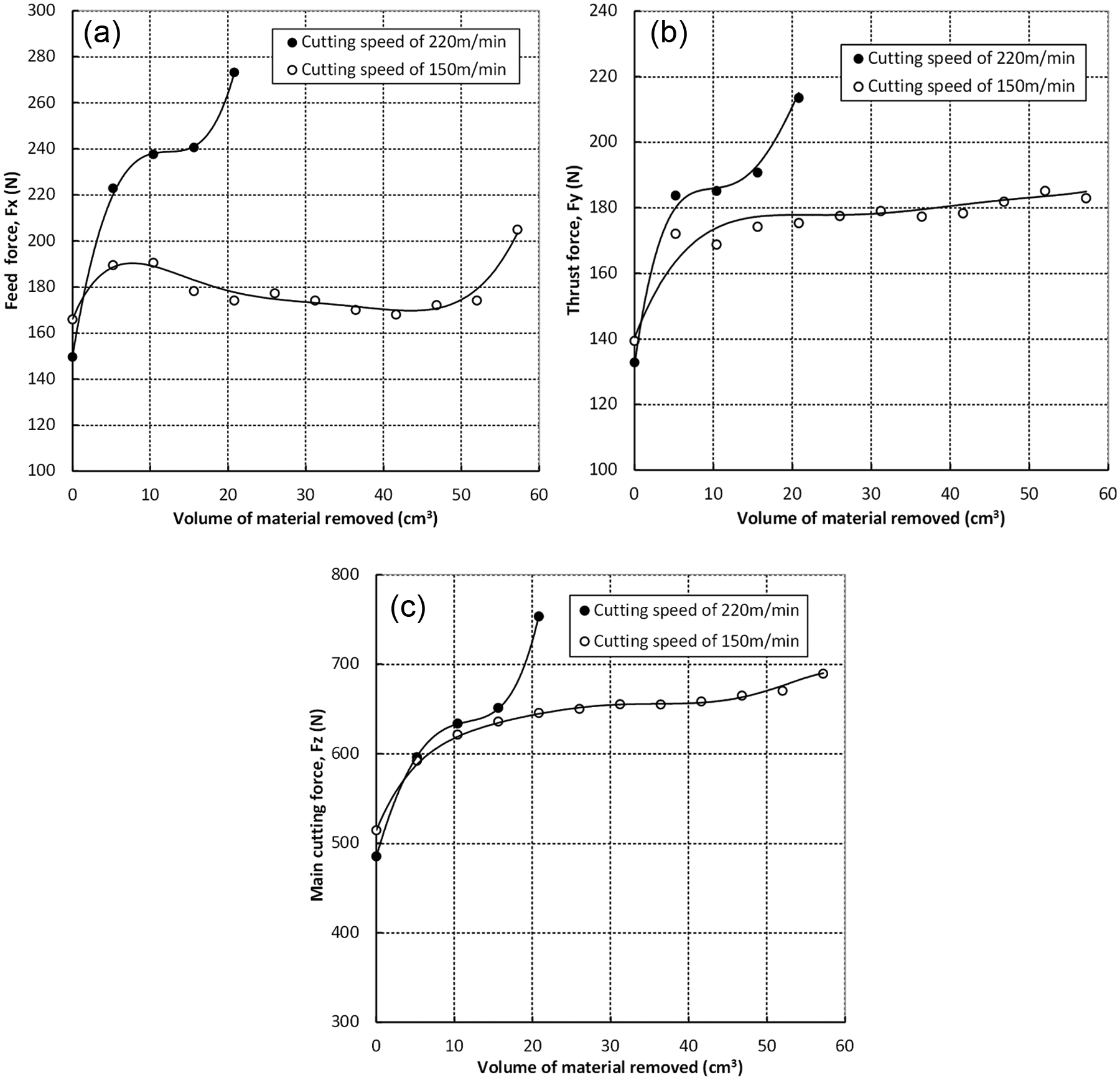
Variation of (a) feed force, (b) thrust force and (c) main cutting force with the volume of material removed at cutting speeds of 150 and 220 m/min.
All three components of the cutting force dramatically increased with increase in the volume of material removed up to about 5.2 cm3 for both cutting speeds of 150 and 220 m/min. The increases in feed force and thrust force were more significant at the cutting speed of 220 m/min than the increases in those forces at the cutting speed of 150 m/min. Hence, the feed force and thrust force during machining at the cutting speed of 220 m/min were significantly larger than those at the cutting speed of 150 m/min when the volume of material removed was greater than 5.2 cm3, whereas the main cutting force at the cutting speed of 220 m/min was significantly larger than that at the cutting speed of 150 m/min only when the volume of material removed was 20.8 cm3 at which tool reached its end of life at the cutting speed of 220 m/min.
Except the feed force at cutting speed of 150 m/min, all the cutting forces, after the initial significant increase, gradually increased with the volume of material removed up to 15.6 and 57.2 cm3 for cutting speeds of 220 and 150 m/min, respectively.
All three components of the cutting force dramatically increased when the volume of material removed was 20.8 cm3, the end of tool life at the cutting speed of 220 m/min, whereas only the feed force showed a significant increase at the end of tool life (the volume of material removed was 57.2 cm3) at the cutting speed of 150 m/min.
In contrast to the variation of the other components of the cutting force with the volume of material removed, the feed force at the cutting speed of 150 m/min was found to decrease slightly with increase in the volume of material removed from 10.4 to 41.6 cm3.
Discussion
During the metal cutting process, significant temperature rise occurs at the cutting zone due to the plastic deformation at the primary and secondary shear zones, friction between the tool’s rake face and flowing chip and friction between the tool’s flank face and workpiece. The cutting temperature is strongly dependent on the workpiece material’s properties (hardness, thermal conductivity, etc.), tool material (thermal conductivity) and cutting conditions (cooling approaches, cutting speed and feed etc.).16,17,45
At the same cutting conditions (cooling method, feed and depth of cut) for cutting titanium alloys, the cutting temperature dramatically increases with cutting speed, which plays a significant role in the tool failure mode and tool life.
Development of tool wear at medium cutting speed and its effect on cutting forces
At the cutting speed of 150 m/min, the tool material at the cutting edge is lost gradually from its flank and rake faces due to the mechanisms of abrasion, adhesion and dissolution–diffusion. The loss of tool material from the rake face resulted in the change in the tool’s rake angle during machining as shown in Figures 8 and 9.
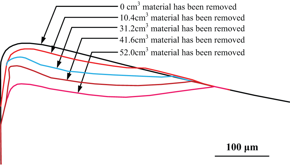
Cross-sectional profiles of the tools at cutting speed of 150 m/min after different volume of material have been removed.
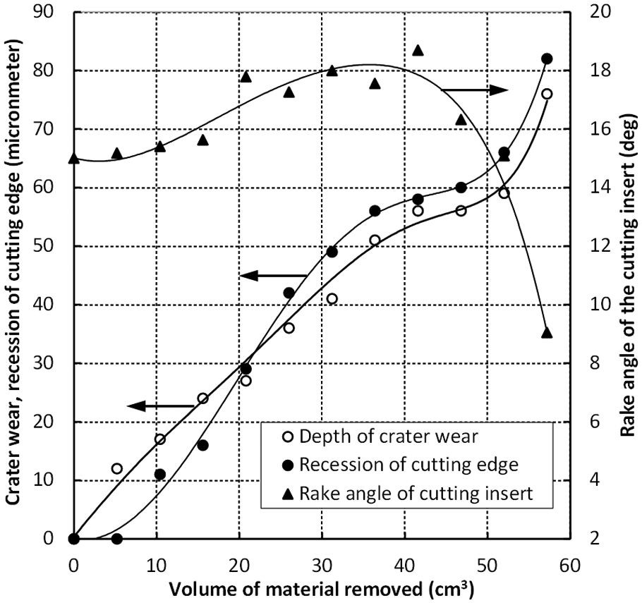
Variation of dimension and geometry of cutting insert with the volume of material removed at cutting speed of 150 m/min.
It can be seen that both the depth of crater wear and recession of cutting edge increase rapidly with the volume of material removed from 0 to 36.4cm3 and reach a steady state when the volume of material removed is between 36.4 and 46.8 cm3 at which the rake angle of the insert increases from its origin of 15° to its highest value of 18.7° due to the loss of tool material from the rake face. The further increase in volume of material removed results in a dramatic decrease in the rake angle, increase in crater wear and recession of cutting edge.
The flank wear at the cutting speed of 150 m/min is steady for the volume of material removed between 10.4 and 52.0 cm3, as shown in Figure 4; therefore, the main cutting force (Fz) and thrust force (Fy) are steady with the increase in volume of material being removed in that range (Figure 7). However, the increase in rake angle with the volume of material removed from 10.4 to 41.6 cm3, as shown in Figure 9, results in a reduction in the feed force (Fx) in that range of volume of material removed as shown in Figure 7. The abrupt increase in the feed force with the volume of material removed from 52.0 to 57.2 cm3 is believed to be due to the sudden reduction of rake angle of the cutting insert.
The SEM images of the tool cutting edge after 57.2 cm3 of material has been removed at the cutting speed of 150 m/min are shown in Figure 10. Chip built-up edges were formed along the cutting edge and on tool’s rake and flank faces due to the strong chemical reactivity between the cutting tool material and titanium at the cutting temperature over 500 °C3,46 The size of chip built-up edge is larger at the tool’s nose corner (marked with A in Figure 10(a)) and depth-of-cut line on primary cutting edge (marked with B in Figure 10(a)). A layer of Ti-rich metal is formed in the top of tool-chip contacted area on the tool’s worn rake face. The variation of the two principal elements, tungsten and titanium, at the tool-chip interface on the line EF in Figure 10(b) is shown in Figure 10(e). The titanium concentration is higher than 75% within 15 µm from the cutting edge due to the chip built-up edge. The titanium layer is thinner in the lower tool-chip contact region (in the region within 15–240 µm form the cutting edge) on the rake face and thicker in upper tool-chip contact area (beyond 240 µm form the cutting edge) on rake face, which might be due to the severe abrasion at the lower tool-chip contact region on the rake face and several shear in chip at the upper tool-chip contact area on rake face. This lower tool-chip contact region corresponds to the deep crater wear (as shown in Figure 10(c)). The Ti-rich layer is believed to be TiC formed as a result of reaction between the Ti from the workpiece and carbon from tool and adheres strongly to the tool (polycrystalline diamond (PCD) and carbide tools 24 ). The uniform TiC layer formed on rake face can minimize the mass transfer of constituents from the tool into the chip and consequently reduce the wear rate.2,12,30,47 –49 However, carbon diffusion results in carbon deficiency in the tool subsurface region, which becomes brittle. 14 The high cutting stress and severe cutting temperatures coupled with the brittleness of the tool substrate due to carbon diffusion may accelerate the chipping, flaking, cracking and fracture of the tool. 50
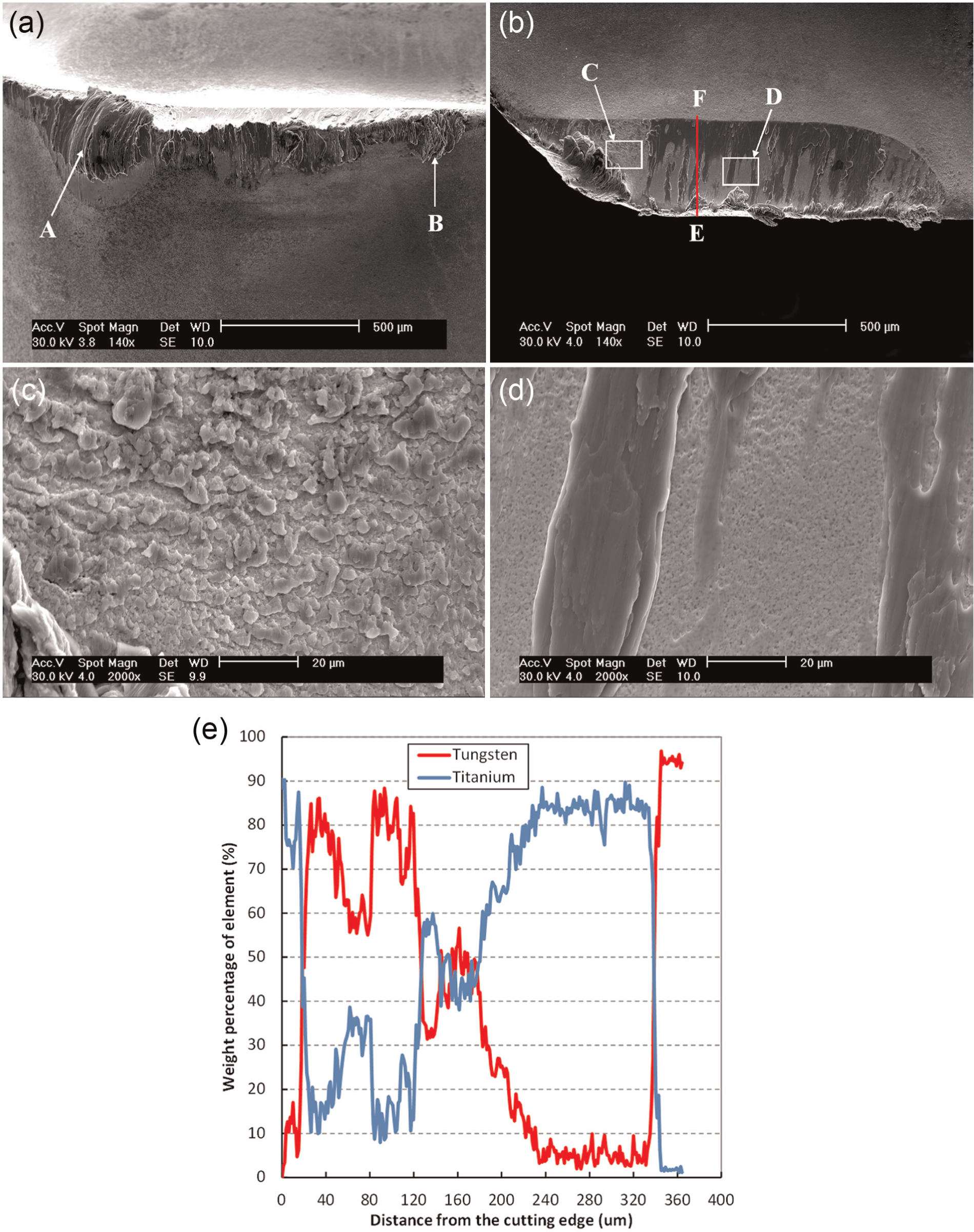
SEM images of (a) flank face and (b) rake face of cutting edge after 57.2 cm3 of material has been removed at cutting speed of 150 m/min. (c and d) are the enlarged selected areas C and D on (b). (e) is the variation of tungsten and titanium on the line EF on (b).
No severe chipping due to the detachment of chip built-up edge from the cutting edge has been found at the cutting speed of 150 m/min. The recession of cutting edge is roughly the same as the depth of crater wear, indicating that the mechanism of recession of cutting edge is the same as that of crater wear, that is, the result of tool material loss due to the combination of wear mechanisms of abrasion, adhesion, dissolution and diffusion. Significant loss of tool material from the rake face resulted in the smaller cross section area at the cutting edge (as shown in Figure 8) that is susceptible to catastrophic fracture if the chip built-up edge is oversized.
The surface of rake face behind the large chip built-up edge at the nose corner (Figure 10(c)) shows different features with those at the middle of depth of cut (Figure 10(d)). The latter shows clear sliding made by the flowing chip, while the former shows discontinuous Ti-rich fragments because the Ti-rich layer was broken into separated fragments due to plastic deformation at tool nose corner.
Effect of tool wear on cutting forces at high cutting speed
With increase in the cutting speed, cutting temperature increases dramatically because of extensive heat generation and reduction in heat conduction into the workpiece.5,41,51 Heat generated during machining tends to be concentrated at the cutting edge closer to the nose of the insert, 9 which leads to oversized built-up edge at the nose and depth of cut, where the principal cutting edge intersects the surface of workpiece during dry machining 19 due to the strong chemical reactivity of titanium with cutting tool materials. Figure 11 shows the significant chip built-up edge at the cutting speed of 220 m/min compared with Figure 8(a) after removing the same volume of material at the cutting speed of 150 m/min.
Cross section of the replicated tool after 10.4 cm3 of material has been removed at cutting speed of 220 m/min.
Cutting tool’s flank and rake faces after 20.8 cm3 of material was removed at the cutting speed of 220 m/min were observed with SEM and are shown in Figure 12. The built-up edge at the nose is much larger than that at the cutting speed of 150 m/min as shown in Figure 10. Both secondary flank face and rake face adjacent to the nose show that cracking occurs at the tool’s nose because of the large plastic deformation of tool at the nose (Figure 12(c) and (d)).
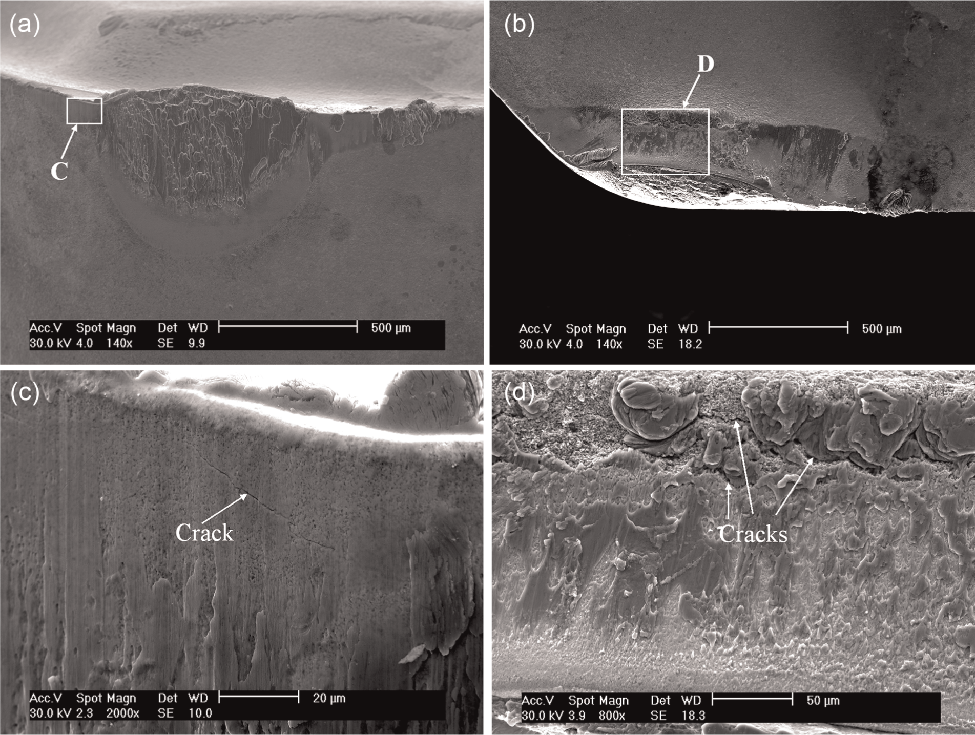
SEM images of (a) flank face and (b) rake face of the cutting edge after 20. cm3 of material has been removed at cutting speed of 220 m/min. (c and d) are the enlarged selected areas of C on (a) and D on (b) showing cracks on secondary flank and rake faces.
The cutting edge after 20.8 cm3 of material has been removed at the cutting speed of 220 m/min, as shown in Figures 6(a) and 12, is pushed up rather than lowered down as reported in the published literature.41,42 The mechanism for pushing up of the cutting edge is depicted in Figure 13. A chip built-up edge is welded on the flank face at the tool’s nose when cutting with high feed rate at high cutting speed due to the high maximum flank wear. 20 Both the stress on the cutting edge and temperature at the cutting edge increase with the growth of built-up edge, the increase in stress and reduction in the strength of cutting tool edge with increase in cutting temperature make it plastically deformed by pushing up. The crack at the nose, shown in Figure 12(c) and (d), is the result of high compressive stress in addition to the plastic deformation.
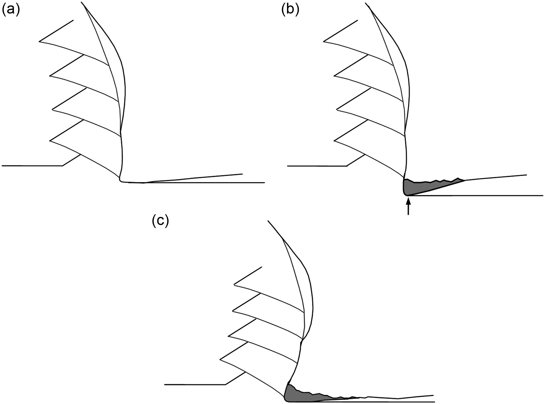
Illustration of the role of built-up edge on flank face in the plastic deformation of cutting edge, (a) cutting without built-up edge, (b) adhesion of built-up edge on flank face and (c) plastic deformation of cutting edge due to built-up edge.
The dramatic increase in cutting forces in all three directions when the volume of material removed is between 15.6 and 20.8 cm3 is the combined results of (1) the bending of the cutting edge at the nose which results in change in the chip flow angle and direction and (2) dramatic increases in friction between flank face and newly produced chamfer surface because of rapid increase of flank wear at nose radius.
The results of tool wear at both cutting speeds of 150 and 220 m/min show the importance of cooling the tool to reduce the diffusion wear and maintain the strength of the cutting edge for longer tool life when machining titanium alloys. Investigation of the effect of enhanced cooling on tool wear will be reported in a follow-up publication.
Conclusion
Investigation of tool wear during dry turning of Ti-6Al-6V alloy in this study draws the following conclusions:
Plastic deformation occurs at the tool nose, which leads to the cutting edge being pushed up rather than the lowering of cutting edge. The plastic deformation region is much smaller at the cutting edge at a cutting speed of 150 m/min after 57.2 cm3 of material has been removed compared with that at cutting speed of 220 m/min after 20.8 cm3 of material has been removed.
Average width of flank wear reaches the criterion due to the recession of cutting edge at the cutting speed of 150 m/min. The rapid increase in the recession of cutting edge and crater wear occurs when the volume of material removed increases from 46.8 to 52.0 cm3, which leads to dramatic reduction in the effective rake angle and increase in feed force only.
Both average width and maximum width of flank wear exceeds the criteria after cutting 20.8 cm3 of material at cutting speed of 220 m/min as a result of severe plastic deformation of the cutting edge caused by rapid increase in the size of built-up edge at tool nose on flank face. The cutting force increases dramatically in all three directions because of the combined effects of (1) change in the chip flow angle and direction and (2) dramatic increases in friction between flank face and newly produced chamfer surface because of rapid increase of built-up edge and flank wear at nose radius.
Footnotes
Acknowledgements
The authors acknowledge the facilities, and the scientific and technical assistance of the Australian Microscopy and Microanalysis Research Facility at the RMIT Microscopy and Microanalysis Facility, at RMIT University.
Declaration of conflicting interests
The authors declare that there is no conflict of interest.
Funding
This research received no specific grant from any funding agency in the public, commercial or not-for-profit sectors.