
Abstract
Previously cubic boron nitride (CBN) and ceramic inserts were used for the dry turning of heat-treated D3 tool steel with cutting speed beyond 200 m/min, suffers from severe tool wear and generation of high temperature at the interface. To overcome these shortcomings, a hybrid ceramic insert that is, Al2O3 + Ti (C,N) with coated (TiN) is used in dry turning of D3 tool steel (heat-treated). Use of the hybrid insert with a lower feed rate (0.04 mm/rev) and a minimum depth of cut (0.4 mm) improves the surface quality of the turning process by significantly reducing the tool wear and cutting forces requirement in a cutting speed range of 165– 175 m/min. Even though ceramic tool inserts have high wear resistance at elevated temperatures but it has limited impact strength. So, ceramics is only recommended for shocks and vibration-free high-speed cutting operations of hardened steel under a dry environment. The novelty of this article is the development of a wear map for the analysis and prediction of tool wear. The Scanning electron microscope studies of wear region elucidate that low tool wear that the predominant modes of wear for low tool wear cutting conditions are delamination and abrasion. Besides for higher tool wear the prevailing wear mode is a combination of abrasion as well as adhesion wear. It is perceived that our proposed methodology outperforms the state-of-the-art methods.
Introduction
The significant demand of industry is to produce a component from hardened workpiece material with reasonable dimensional tolerance and surface quality. Owing to the successful metal removal, improved surface quality, and dimensional precision, the turning of heat-treated steel (beyond HRC 45) within a dry environment has acknowledged significant interest as compared to conventional grinding. 1 The hard turning within a dry environment is one of the suitable metal removal methods to control the machining constraints viz. environmental pollution and turning cost. 2 Initially, Kumar et al. 3 performed a parametric analysis of horizontal turning of D2 steel by employing (Al2O3 + TiCN) hybrid ceramic insert. Further, the authors have addressed the issues that arise at the tool tip because of cutting forces and friction under an accelerated cooling environment. Later, this is manifested in the analysis performed by Grzesik et al. 4 wherein, an empirical model using the volume of chip removed and the magnitude of cutting speed was developed for flank wear prediction. But the initiation or propagation of tool wear was studied by Olander and Heinrichs. 5 In this study, cemented carbide grade H13A was considered for turning titanium alloys. The result revealed that the wear is shallow and happening on a very small scale which adds up to a larger crater. A further extensive study by Ramana et al. 6 investigated the machinability of A 286 alloy in turning by employing carbide tool inserts (both uncoated and physical vapor deposition (PVD) coated). The researchers observed that PVD-coated insert exhibits less tool wear as compared to uncoated one. But in another extensive study, Boing et al. 7 analyzed tool wear level and its correlation with the wear mechanism during turning of hardened steel (with six different levels of hardness) with a polycrystalline cubic boron nitride (PCBN) tool. In a study that set out to explore the impact of turning performance parameters while turning heat-treated D3 tool steel, various researchers have established an interrelationship between process parameters and process responses and also specified the range of process parameters to control tool wear along with other process outputs. The study has recounted that axial feed along with a depth of cut controls the heat developed on the tool’s surface, 8 while an ultimate cutting speed of 240 m/min was suggested to limit excessive wear on the TiN coated CBN tool insert. 9 In a minor study by taking advantage of CBN inserts in the course of turning of D3 tool steel, Bouchelaghem et al. 10 have established an interrelationship between the rate of tool wear, the surface roughness of the machined, the magnitude of cutting forces, and temperature in the machining region. In the latest methodological study, Bhemuni et al. 11 divulged that the nodal temperature rise in the cutting region is due to both depth of cut and axial feed, however, depth of cut as well as cutting speed are principally accountable for flank wear during machining of hardened D3 tool steel with a ceramic insert. While Aouici et al. 12 proposed the response surface methodology (RSM), as well as a desirability function-based optimization of response characteristics in the machining of heat-treated D3 tool steel with TiN coated hybrid ceramic inserts. Further, Bhemuni and Rao 13 have suggested RSM-based regression models for the analysis of turning of heat-treated D3 and H13 tool steel with a hybrid (Al2O3/TiC) ceramic insert. Similar analyses were also attributed for tool wear evaluation and performance study of process parameters on process responses. It is noticed that adhesion is the major mechanism of wear for hybrid tools in turning AISI 304 steel. 14 Further, the researchers have performed micro-turning using cermet insert and stated that optimum machining conditions to produce the minimum tool wear that is, 0.133 mm are cutting speed of 3459 rpm, with depth of cut 15 µm and axial feed rate 7.4 µm/rev. 15 While PVD coated TiAlxN super nitride on carbide tool is considered as the best alternative of CBN tool with comparable tool life and machining cost. 16 Similarly, the study revealed that smaller feed and greater cutting speed are recommended for better performance using alumina-based ceramic tool. 17 While axial feed rate is the most commanding machining parameter that controls the surface roughness and flank wear 18 and an increase in feed rate will result in the substantial increase of process responses. 19 It was also proposed that low surface roughness and minimum cutting forces can be accomplished using AlCrN coated inserts. 20 Further, the researchers proposed an alternative machining strategy during turning of Inconel-800 superalloy under minimum quantity lubrication condition and observed its performance over flood cooling due to its better control on parameters that is, cutting fluid and compressed air. 21 Apart from this, two primary tool wear mechanisms that is, adhesion and abrasion were noticed during machining of non-treated steel while adhesion wear mechanism for the calcium treated steel along with chipping of the cutting edge at longer tool live. 22 Despite the fact, Bustillo et al. 23 studied the outcome of a new machining strategy for accuracy improvement of the machine-learning model. In a major study, the researchers have investigated the performance of cryogenic treated CBN inserts, 24 carbide inserts, 25 and ceramic inserts 26 within the dry turning environment of C22 superalloy. A similar analysis was also performed to control thrust force and surface roughness by optimizing the process parameters using Taguchi technique. 27 In an in-depth study, Sagar et al. 28 observed the growth of flank wear and its influence on machining responses and noticed that the predominant mode of wear is adhesion. Further, Tian et al. 29 observed the carbide tool performance in dry turning of GH2132 superalloy. The study depicted that at low cutting speed, the predominant mode of wear is adhesion and abrasion and at the same time at high cutting speed the predominant mode of wear is adhesion. A similar analysis in the turning of AM alloy 30 was also performed to study the influence of process variables on process responses.
Further, the concept of a wear map to analyze various wear regimes is considered to be an effective approach to categorize various wear mechanisms. Initially, a graphical representation of tool wear is proposed by Trent. 31 While, the first qualitative tool wear-map is proposed by Yen and Wright 32 and demarcated the safety zone for machining. Further, a step has been taken by Kendall 33 and proposed a strategy for a safe operating region for cutting tools by overlapping possible boundaries onto the wear-mechanism map for steels. Later this wear map concept was implemented by Lim et al.34,35 and concluded a final wear map showing three major regions of machining conditions. 36 These are (i) least damage region, (ii) normal cutting region, (iii) finish turning region. A similar study was carried out by Liu et al. 37 using PVD-TiAlN coated carbide insert during turning of Inconel 625. The proposed map also indicates a safe zone to define the optimized range of parameters.
Collectively, the literature survey involving dry turning of D3 tool steel (heat-treated) with ceramic and various coated carbide inserts mostly highlights the parametric analysis. However, in most of the studies, it is reported that tool wear becomes very high when cutting velocities exceed 200 m/min. With CBN tool inserts the interface temperature rise is very high when cutting speed exceeds 200 m/min and beyond 240 m/min the tool wear is severe. Whereas turning of D3 steel with Al2O3/TiC mixed ceramic turning tool has reported a severe rise in interface temperature beyond a cutting speed of 180 m/min. So the use of CBN, the ceramic tool with TiC or TiN coating suffers from the following flaws (i) at a higher cutting speed that is, beyond 200 m/min, there is severe tool wear, (ii) at high cutting speed, with low feed rate & high depth of cut, the interface temperature rise is very high resulting in lowering of tool life, (iii) although feed rate has little influence on interface temperature generation at low to medium cutting speed higher feed rate resulted in poor surface quality. This has motivated us to investigate the turning of D3 heat-treated steel under dry environment using a ceramic insert that is, Al2O3 + Ti(C,N) with coated (TiN), so that desired level of surface quality with controlled tool wear can be addressed with a cutting speed lower than 200 m/min. So, the central focus of the current study is turning of D3 tool steel (heat-treated) using a ceramic insert that is, Al2O3 + Ti (C,N) with coated (TiN) within a dry environment. Hardened D3 tool steel is a unique material with superior resistance to wear and exhibits good strength and oxidation resistance and finds its applications in the manufacturing of tools that require high strength like blanking and forming dies, press tools, punches, bushes, etc. The selected hybrid insert has exceptional wear and temperature resistance due to the presence of coated (TiN). The presence of Ti (C,N) and TiN coating is likely to influence the mechanism of tool wear and surface quality. Because of wear resistance, hybrid ceramics tool insert is only recommended for shocks and vibration-free high-speed cutting operations of hardened steel under a dry environment. Hence, it becomes indispensable to analyze and characterize the different regimes of wear with the intention to get an insight into the mechanism of tool wear, and their control through cutting variables. In this paper, we have developed a tool wear map and proposed a study for tool wear analysis for this hybrid ceramic tool insert. The wear map developed will assist the user to estimate the approximate tool life for a given cutting condition. The design scheme of the research proposed in this study is shown in Figure 1.
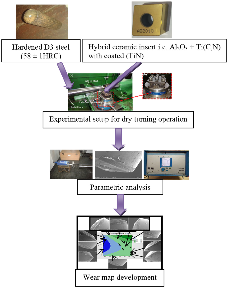
Design scheme of the research.
Materials and methods
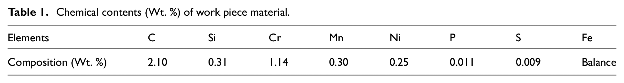
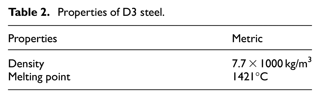
The experiments are performed to analyze the various mechanisms of tool wear in turning of D3 (ϕ70 × 500 mm with hardness 58 ± 1HRC) heat-treated tool steel under a dry condition with a ceramic tool insert that is, Al2O3 + Ti(C,N) with coated (TiN). Initially, the workpiece material selected for dry turning was subjected to heat treatment at about 920°C (austenitization temperature) for half an hour, followed by oil quenching. Subsequently, at 400°C tempering was performed for 2 h, and thereafter cooling was carried out to reduce the residual stresses and achieve a uniform structure. A typical workpiece hardness of 58 ± 1HRC was obtained after the heat treatment. The hardness of the workpiece was tested by using a Rockwell hardness tester. The chemical composition of D3 steel includes high carbon and high chromium, which exhibits good strength and oxidation resistance. The chemical compositions and physical properties are reported in Tables 1 and 2 respectively.
Chemical contents (Wt. %) of work piece material.
Properties of D3 steel.
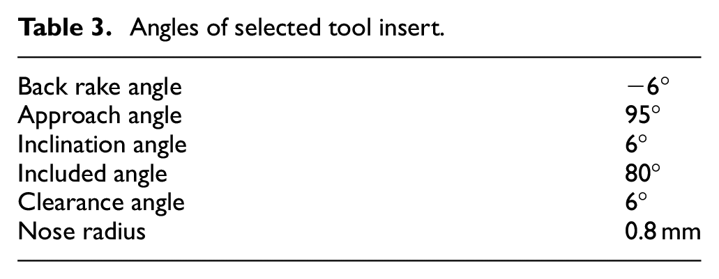
Further, the selected tool insert has a thin layer of TiN coating (1 µm) and is retained over a mixed ceramic substrate using the PVD process to improve its wear and fracture resistance in a dry machining environment. This combination of tool inserts and coating also provides significant economic benefits over the CBN tool. The insert (grade – CW2015, ISO designation – CNGA120408T02020) was mounted on the tool post (WIDIA make – ISO designation PCLNL 2525 M12) as depicted in Figure 2, and its angles are reported in Table 3.
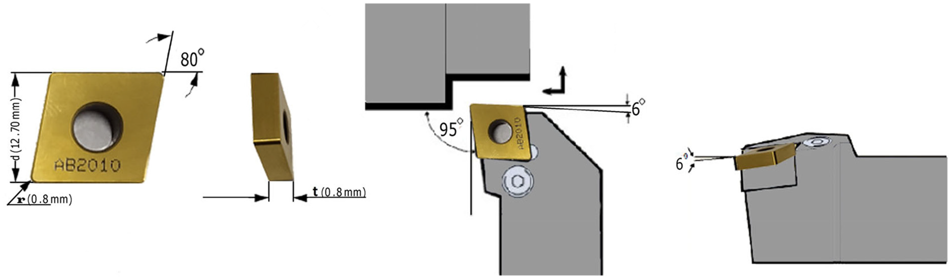
Tool insert and its dimensions.
Angles of selected tool insert.
Experimental details
In this study, a turret lathe with spindle power 6.6 KW (Make Kirloskar model Turn master – 35) was utilized for machining purposes (as shown in Figure 3(a)–(c)). The overall setup shows the workpiece clamped on the lathe chuck with its tool holder firmly mounted in place on the fixture and the fixture is connected with a lathe tool dynamometer for force measurements.
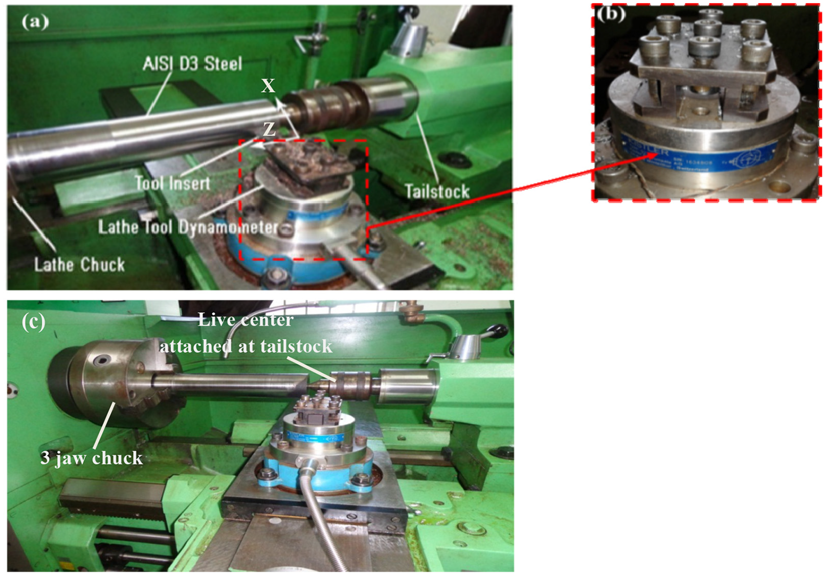
(a) Lathe machine setup for turning operation, (b) dynamometer, and (c) experimental setup.
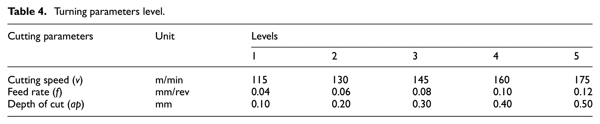
Several trails of hard turning experiments under a dry environment have been carried out as per the available literature to select the feasible range of the process variables (i.e. cutting speed, axial feed rate, and depth of cut). However, for the sake of simplicity, the range of the cutting parameters is decided according to the acceptable level of surface finish, material removal rate (MRR), and tool wear. The different cutting variables in conjunction with their variation levels are reported in Table 4.
Turning parameters level.
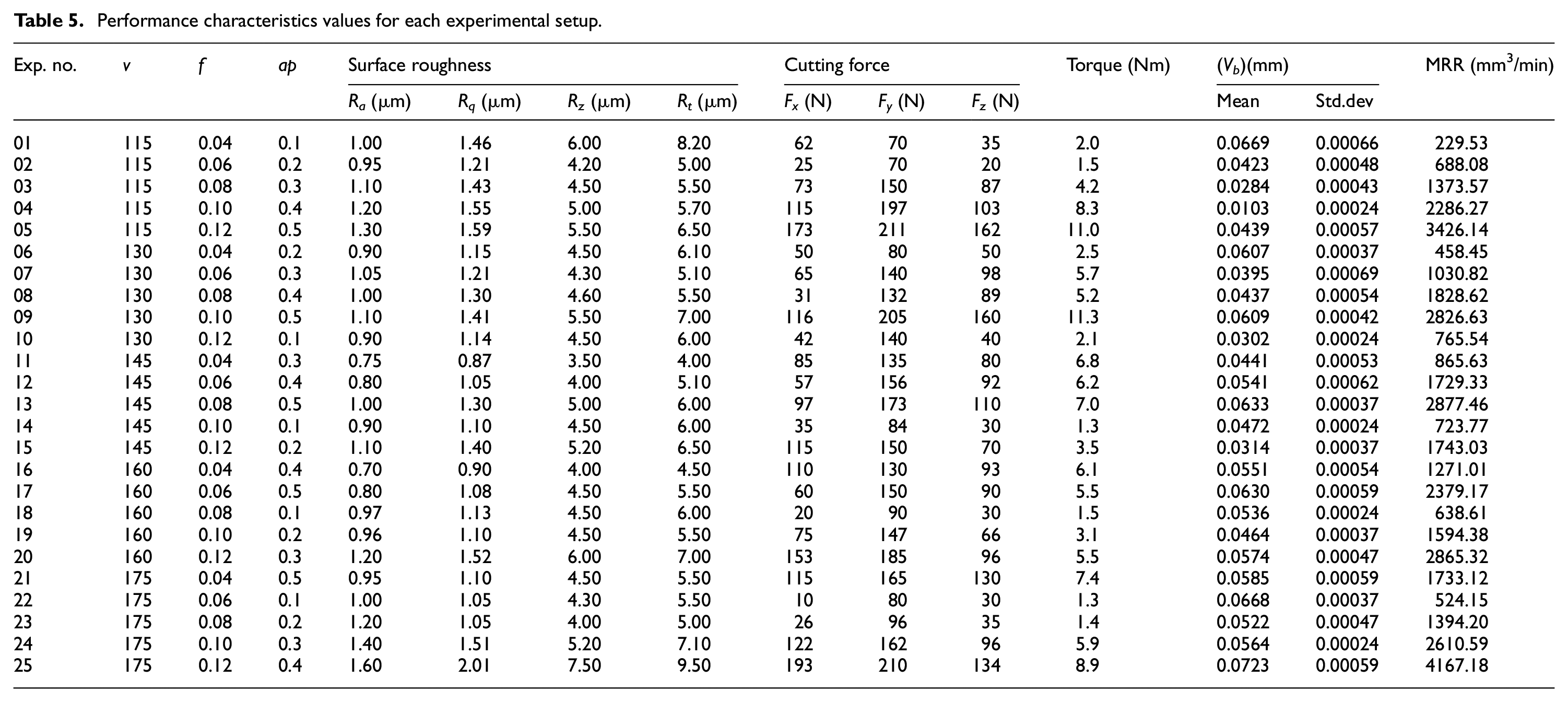
A sequential design of the experiment was planned according to the factorial design of experiment. The L25 (53) orthogonal array using Minitab-17 software was used to assure equal consideration of all levels of all factors for independent evaluation of the responses. In this study, the various response characteristics viz., surface finish, cutting forces, torque, tool flank wear (Vb), etc. are considered (considering mean after five repetitions of measurement) during hard turning (with a constant machining time of 10 min for each parametric condition using a separate new tool) under a dry environment. To quantify the roughness of the machined surface, well established stylus-type portable profilometer (Mitutoyo SJ-210) with skid force less than 400 mN and a measuring length of 17.5 mm was used. Various essential machined surface quality parameters like Ra (roughness average), Rq (root mean squared roughness), Rz (10-point height average of the profile), and Rt (maximum height of the profile) have been measured on the machined surface. A high accuracy dynamometer (KISTLER Type-9257B) with an amplifier (KISTLER Type-5070) has been used with a data acquisition system for measurement of different forces (viz. Fx (radial thrust force), Fy (tangential cutting force), and Fz (feed force)) as well as the torque. In this study, scanning electron micrographs (SEM of HITACHI make SU3500) equipped with energy-dispersive X-ray spectroscopy (EDS of Oxford INCA x-act model) pattern was used for tool wear characterization. The design scheme of the research is shown in Figure 1.
Results and discussions
Turning operation under dry environment was performed as per the pre-defined experimental plan and the output responses are recorded (Table 5). We reasoned that, by repeating the randomly chosen experiments from the result analysis, the reliability of the lathe machine was confirmed and this may be a technology-specific artifact involving variation in results within ±3%.
Performance characteristics values for each experimental setup.
Parametric analysis of tool wear
The tool wear in a single-point tool insert is confined within the flank surface, rake surface, clearance face as well as nose radius. Wear types disclose evidence about the extensive performance of machining operations. 38 Machining conditions, the temperature rise at the work piece-tool interface, effective chip control throughout the machining operation, surface quality requirements, etc. are primarily dependent on tool wear. This study depicts the control of tool wear through process variables during dry turning of D3 tool steel (heat-treated). The out-turn of different process variables on flank wear (Vb) at a high level (i.e. fifth level) of hold values is presented in Figure 4. It can be noticed from the contour plots that, Vb increases as the axial feed rate and depth of cut rises. It is also witnessed that, Vb rises at lower cutting speed, as well as axial feed rate but, declines with a corresponding increase in axial feed rate. Thus, from the study, it can be accomplished that axial feed rate is the controlling factor for Vb after cutting speed as well as the depth of cut. This is because of the high friction and temperature resulting from a higher axial feed rate and depth of cut. The SEM micrographs of tool flank wear (i.e. mean flank wear) are depicted in Figure 5(a) and (b) respectively.
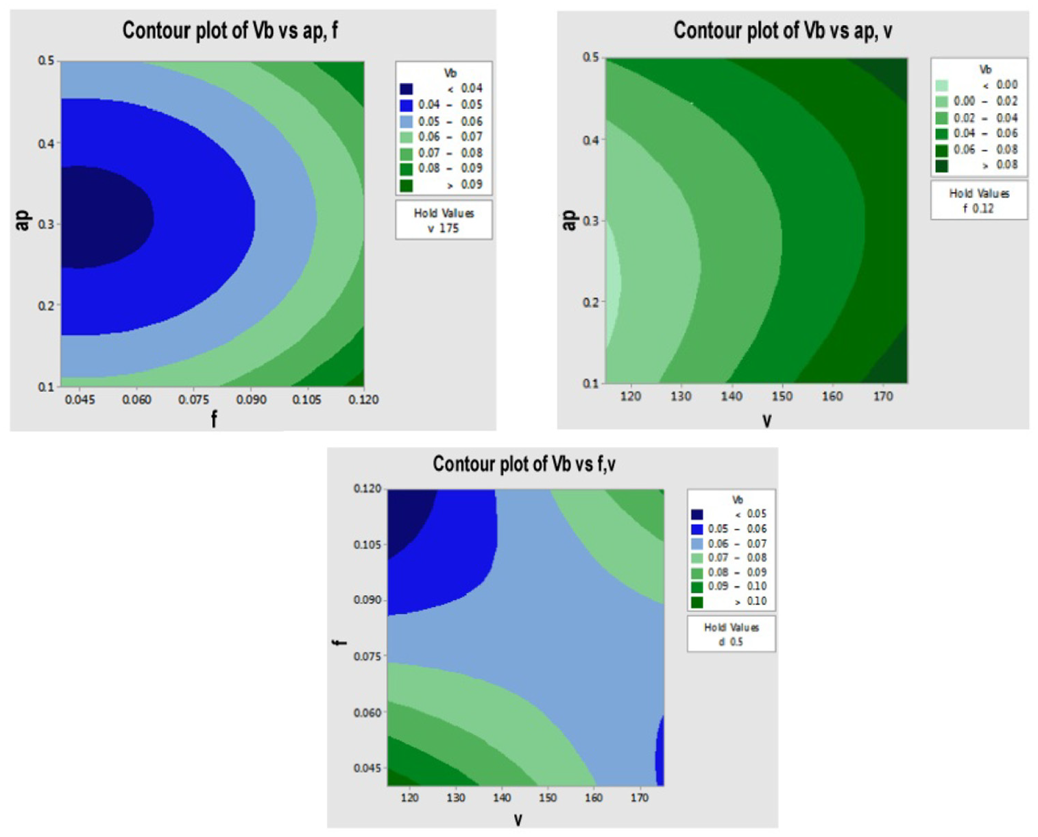
Response of flank wear (Vb) w.r.t. process variables.
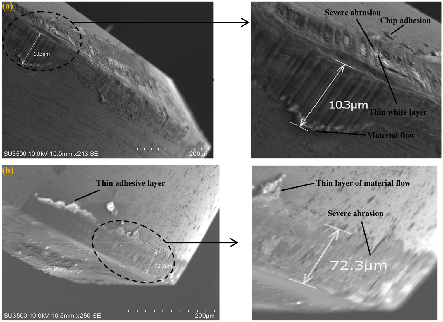
SEM micrograph of flank wear measurement at (a) v (115 m/min), f (0.10 mm/rev), ap (0.4 mm) and at (b) v (175 m/min),f (0.12 mm/rev), ap (0.4 mm).
The rise of flank wear as regards cutting speed is owing to the high friction prevailing at the chip-tool interface. At higher friction, there is an increase in pressure and temperature on the cutting edge of the insert. This confined heating leads to chipping and an increase of flank wear.39,40 In dry turning, high temperature at the cutting zone accelerates thermally activated wear (abrasion) of the tool due to work softening. In this case, the sticking of chips on the tool surface occurs owing to high friction at the chip-tool boundary. Also, abrasion wear phenomena on the tool surface are reported owing to high pressure on the tool. 9 Nevertheless, the data obtained using SEM to analyze the machined surface may provide more sensitive information for assessing the impact of cutting variables on the response characteristics. Figure 5(a) illustrates the flank wear on the tool surface. There is clear evidence of severe abrasion on the rake surface along with chip adhesion. Severe abrasion and a thin layer of material flow occur on the tool surface and the substantiation for this can be seen in Figure 5(b). This may be attributed to the fact that at high cutting speed and depth of cut severe abrasion and material flow occurred because of higher frictional heat generation. It is worthwhile to point out here that, thermal shock and plugging effect dominate at an elevated depth of cut and it leads to chip adhesion and severe crater wear on the tool rake surface (can be seen in Figure 6). A similar type of observations was moreover found in Sharma et al. 41 and Dureja et al. 42
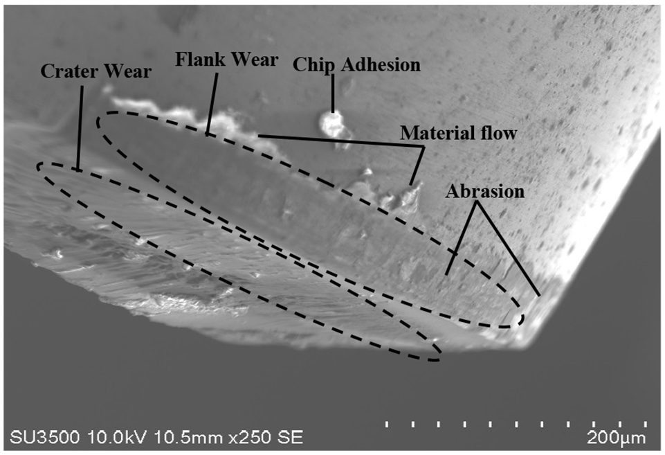
SEM micrograph depicting tool wear.
Similarly, in this study, severe abrasion patterns, material flow, etc. were also observed due to plastic deformation noticed on the flank face (because of high-temperature generation in dry turning) of the tool. Thus, a machining strategy for this type of tool-workpiece combination to achieve minimum tool wear can be a higher cutting speed along with a low depth of cut and axial feed rate.
Characterization of tool wear
The characterization of tool wear of the inserts was conducted by EDS analysis together with SEM images. Figure 7(a) and (b) shows the SEM image and EDS spectrum of worn tool inserts during experiment numbers 16 and 25 respectively. A slight color change was indicated near the nose radius, which may be due to mild adhesive wear. EDS analysis indicates the presence of Fe, C, O, Si, Al, Mn, Ti, Cr, and Mg elements on the tool surface. The elements Ti and Al form the cutting tool insert material while Fe, Mn, Si, and Cr were diffused from the workpiece after turning operation at a high cutting speed and axial feed. The diffusion of these elements occurred because of the prevailing temperature at the tool work-piece interface.
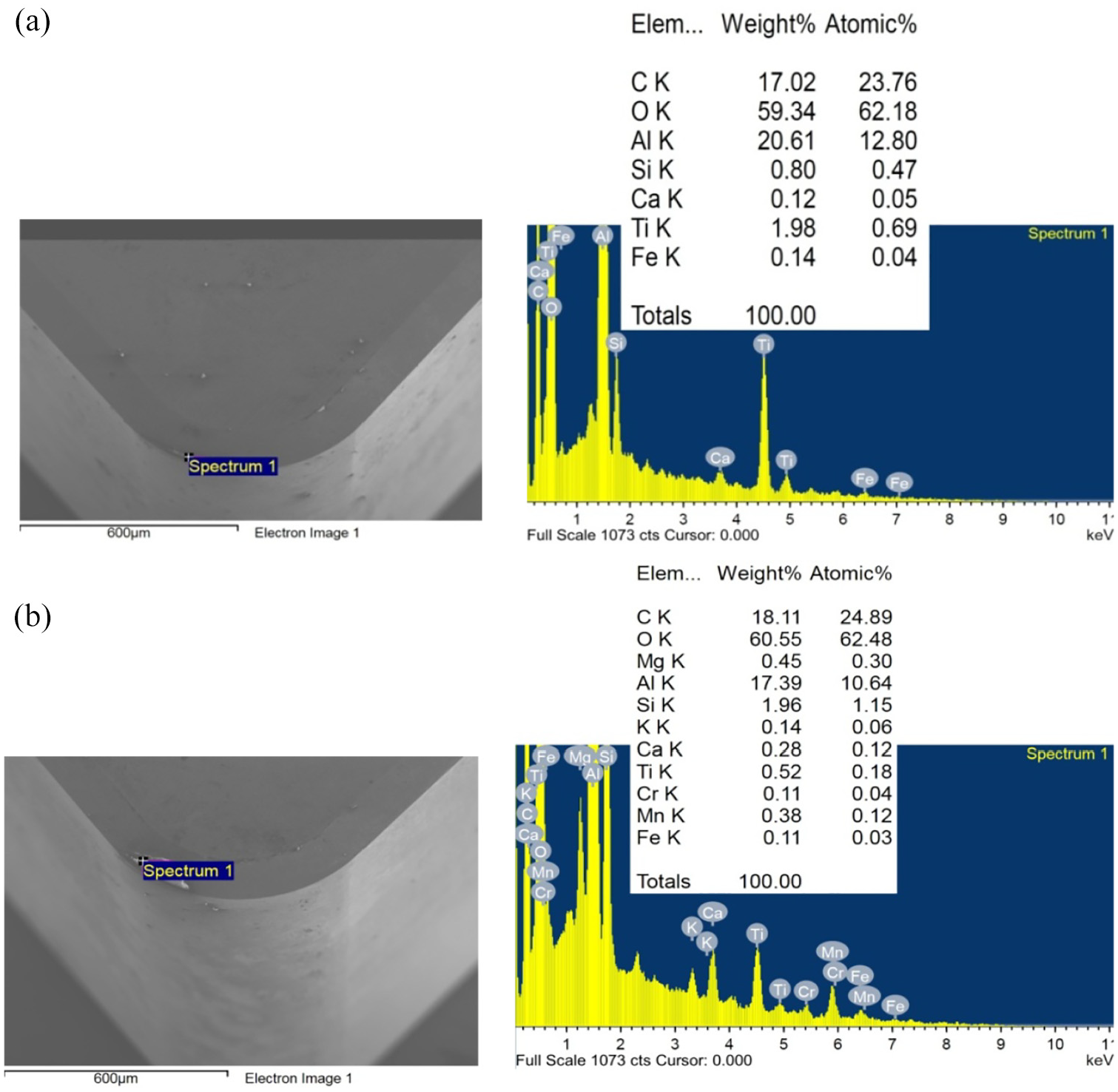
(a and b) Wear pattern with EDS spectrum at (a) v (160 m/min), f (0.04 mm/rev), ap (0.4 mm) and at (b) v (175 m/min), f (0.12 mm/rev), ap (0.4 mm).
The chemical compositions were evaluated at the selected spectrum under two separate cutting conditions (exp. #16 and #25). The EDS spectra presented here is discriminating the chemical composition of micro-particles. Figure 7(a) shows moderately low iron concentration as compared to a fairly high C and Al concentration. This may indicate the existence of aluminum in the form of oxides. However, the subtle presence of iron indicates lesser diffusion over the hybrid ceramic tool coating. Besides the existence of oxygen and carbon, aluminum is another major element in the spectrum as shown in Figure 7(b). The high content of Al (17.39 wt.%) indicates the presence of superficially oxidized particles near the nose radius.
Wear regimes
A wear-regime map provides a useful method of depicting the various regimes where a range of modes of wear dominate. Though hybrid ceramic tool has higher hot hardness and wear resistance, it is subjected to wear under high-speed cutting conditions (above 500 rpm). So, it becomes essential to explore the different modes of wear occurring in this type of tool insert. Most notably, this is the first study to our knowledge to develop a wear map, indicating the different wear regimes of mixed ceramic tools in dry turning of D3 steel. The wear map developed in this study is depicted in Figure 8.
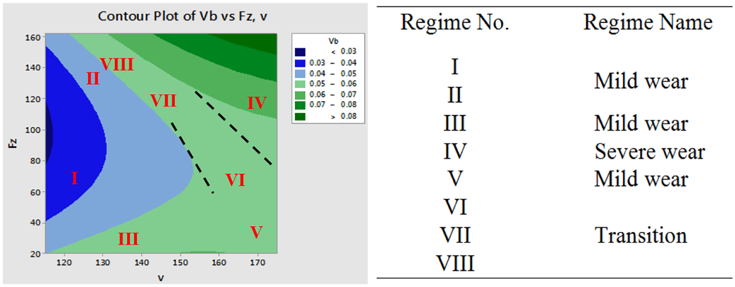
Contour plot with various wear regimes (wear map).
The map is plotted with feed force and cutting velocity. The dominating mechanism of wear and the subsequent regions on the map are shown distinctly. The mechanics of tool wear in the various regimes are discussed as follows.
Regime I – When the feed force is high at a comparatively low cutting speed range, the plastic flow dominated the wear mechanism (Regime I). It involves adhesion, shear, and development of subsurface cracks resulting in the formation of lamellar wear particles that is, delamination wear. Under low cutting speed, high feed force these plastically dominated wear mechanism prevails (Figure 9(a)).
Regime II – At a low cutting speed and high feed force, penetration of hard surface occurs, leading to high wear rate, formation of a thin layer with oxide particle, and development of material flow (as depicted in Figures 5(a) and 9(b)).
Regime III – At a lower feed force and low cutting velocity, the resulting wear rate is low due to lesser temperature release during the turning (mild wear). In this regime, mild feed marks as a result of rubbing of the chip can be observed on the SEM micrographs (Figure 9(b)).
Regime IV – High feed force and high cutting speed result in increased friction with high frictional heating. But due to inadequate thermal conductivity of ceramic material, partial heat is removed from the tool-workpiece boundary and it results in severe adhesion and abrasion wear (Figure 5(b)).
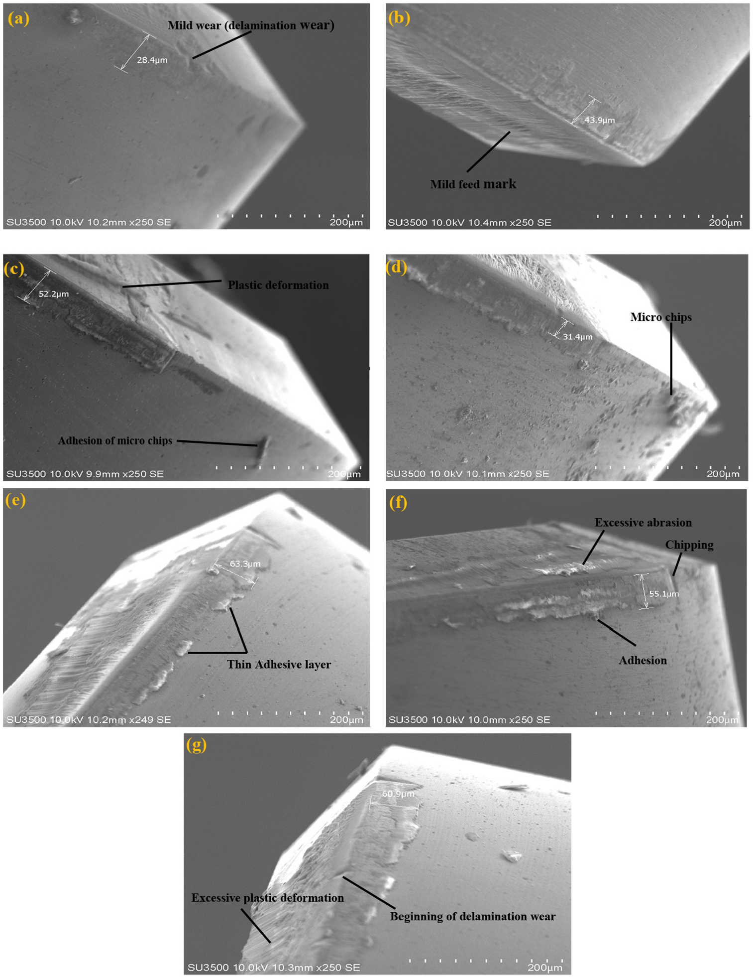
Wear phenomena under (a) regime I (v (115 m/min), f (0.08 mm/rev), ap (0.3 mm)), (b) regime II (v (115 m/min), f (0.12 mm/rev), ap (0.5 mm)), (c and d) regime V (v (175 m/min), f (0.08 mm/rev), ap (0.2 mm) and v (145 m/min), f (0.12 mm/rev), ap (0.2 mm)), and (e–g) regime VI–VIII (v (145 m/min), f (0.08 mm/rev), ap (0.5 mm), v (160 m/min), f (0.04 mm/rev), ap (0.4 mm) and v (130 m/min), f (0.10 mm/rev), ap (0.5 mm)).
It is, therefore, speculated that this phenomenon will lead to the presence of a thin adhesion layer on the flank surface. The development of abrasion marks is because of the chipping of the cutting edge after prolonged use.
Regime V – In regime V, the prevailing cutting conditions are lower feed force and high cutting speed. In this regime, the interface temperature is high and it promotes plastic deformation of the material (Figure 9(c) and (d)) on the rake surface. The adhesion of the micro-chip on the flank surface indicates the presence of adhesive wear.
Regime VI, VII, VIII – The VI, VII, and VIII regimes occur across a narrow range of cutting speed and they portray different types of translational behaviors between the extremes that is, medium cutting speed and high cutting speed. At a medium cutting speed and high feed force, the thermal effect starts playing a key role at the boundary (Figure 9(e)). A thin adhesion layer with a feed mark on the rake surface is noticed (Figure 9(e)). At a high cutting speed and medium feed force, the thermal effect becomes more serious leading to excessive abrasion and adhesion wear (chipping at the cutting edge) (Figure 9(f)). At low cutting speed and high feed force conditions, severe sliding will occur. It is believed that excessive sliding may sometimes be considered as a contributing factor for the onset of delamination wear and excessive plastic deformation of material on the rake surface (Figure 9(g)).
By using this concept, we have proposed a qualitative wear map to identify and control the wear mechanism. The various wear regimes have been identified using the proposed wear map (as can be seen in Figure 10) by performing the machining at a constant machining time of 10 min only. If the wear mechanism is severe then qualitatively, we can predict that the tool is going to fail in a short span of time. However, in actual production condition, the machining will be performed for a longer period of time till the tool life is over. If we want to quantitatively predict the wear, then the following procedure should be adopted. For example, consider a point on the wear map, the coordinates of the point denote the cutting condition, that is, the abscissa denote the cutting velocity whereas, the wear regime denoted the depth of cut as well as axial feed rate. So, one can set the cutting condition that is, cutting velocity, depth of cut, and feed rate (depending upon the wear regime), and then the experiment will be performed till we achieve flank wear of 0.3 mm1. The time to achieve the wear condition is an approximate indication of tool life for that specific cutting condition.
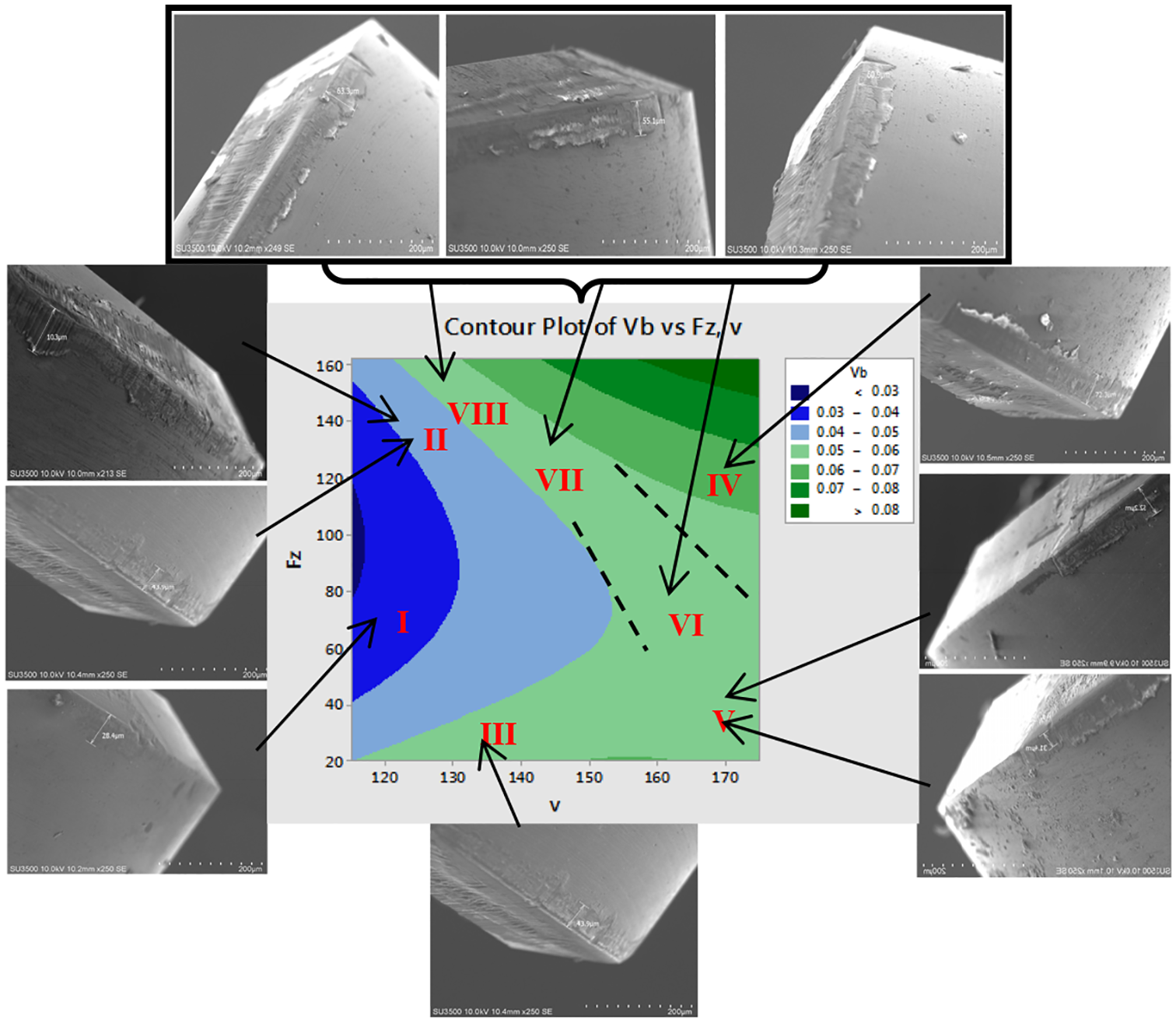
Wear regimes using proposed wear map.
These findings have the potential to explore the suitability of ceramic insert that is, Al2O3 + Ti (C,N) with coated (TiN) for any manufacturing process involving dry turning of hard materials.
Conclusions
This paper provides a framework for the development of a wear map for tool wear prediction. The proposed study is simplifying the complex system of dry turning of D3 tool steel and it will assist in the prediction of tool wear mechanism and control. Some of the most significant findings to emerge from this study are:
The use of CBN and ceramic inserts for turning of D3 tool steel (heat-treated) in dry environment with a cutting speed around 240 m/min has resulted in severe tool wear. This shortcoming has been overcome with the use of a hybrid ceramic insert at a cutting speed much below 240 m/min that is, 170 m/min. Besides a better surface finish has been reported in the study, that is, Ra (0.7 µm) within a cutting speed range of 160–180 m/min.
Based on the parametric study and wear analysis, a wear map has been developed in this work for tool wear prediction and control. The wear map can be used to predict the approximate tool life under a prevailing cutting condition.
The wear analysis has clearly revealed that the predominant mode of wear for low tool wear cutting conditions is delamination and abrasion wear, whereas, for a higher degree of tool wear the mechanism involves a combination of abrasion as well as adhesion wear.
In the wear map translational behaviors are noticed between the extremes that is, low to high cutting speed. The wear behavior changes from the mild delamination wear to the temperature-controlled wear that is, adhesion and abrasion as there is a transition in cutting velocities from low to high range.
The EDS study discovered the existence of a superficial oxide layer near the nose due to high-temperature chemical diffusion across the interface. This oxide layer is brittle in nature and at the extreme cutting condition, it leads to chipping of the tool near the nose.
The SEM micrograph has clearly indicated the abrasion pattern and material flow on the flank face due to plastic deformation. This is because of high-temperature generation in dry conditions. It is also observed that the quantum of wear is primarily reliant on the depth of cut as well as axial feed rate. Correspondingly, the SEM micrograph has discovered the material flow and formation of the oxide layer at lower cutting speed, high depth of cut, and axial feed rate.
The purpose of rigorous experimental study and machining is to enhance the performance of hybrid ceramic tool inserts, wear mechanism, and dominant failure mode of the tool under the different cutting condition that improves the machinability of D3 steel. The findings in the present study are encouraging and should also be investigated for other tool-workpiece combinations.
Footnotes
Appendix
Acknowledgements
The authors duly acknowledged the facility provided by the Department of Production Engineering, VSSUT, Burla.
Declaration of conflicting interests
The author(s) declared no potential conflicts of interest with respect to the research, authorship, and/or publication of this article.
Funding
The author(s) received no financial support for the research, authorship, and/or publication of this article.