
Abstract
Freeform complex surfaces have become an essential part of many devices to perform the required functions. Many of these components require nanometer-level surface finish to perform the desired functions efficiently. In this work, an attempt has been made to improve the external morphology of freeform surfaces, especially knee joint, by abrasive flow finishing process. A uniform mirror finished surface with improved finishing rate is achieved for stainless steel knee joint. Extrusion pressure is varied to reduce final surface roughness value and finishing time. Experimentally, good surface finish ranging from (Ra) 42.9 to 62.5 nm is achieved at various locations of the knee joint which are within the recommended American Society for Testing and Materials standard (≈100 nm) of knee joint prosthesis. Effects of abrasive flow finishing process parameters are investigated to develop “know how” of the process on the freeform surfaces. Abrasive flow finishing process has given 76.56% reduction in finishing time as compared to the time required by “ball end” type tool used for finishing knee joint.
Introduction
Currently, about 5 million people in the world are diseased by arthritis. This painful inflammation is often cured by an artificial knee joint replacement. 1 It is a well-known fact that in the developed countries, the percentage of elderly persons within the total population is growing fast. This demographic shift has tremendously increased the health care demands for aged persons. 2 Osteoarthritis is the gradual degeneration (necrosis) of the natural cartilage tissue, which plays an important role in the load bearing and friction minimizing functions of hip and knee joints. The health problems due to this tissue break down can be treated by prescribing anti-inflammatory drugs and exercise. In extreme cases, the replacement of all or part of the knee joint with artificial implants or prosthetics is the last resort. At present, the life span of such systems is 5–15 years. 2 Increasing life expectancy and practice of extreme sports, obesity and hectic lifestyle are leading to increased wear of bones and joints. One of the effective ways to overcome these problems is the implantation of an artificial joint. The main weight bearing joints of the body like knee and hip joints are the principal target of such replacements.
Functions, fabrication, and finishing of artificial knee joint
Knee joint implants typically consist of metallic femoral and tibial components with a plastic polyethylene insert kept between them to restore joint function as shown in Figure 1. The knee joint is subjected to a complex combination of sliding and rotational movements. Wear by abrasion is one of the main causes for failure of artificial knee joint over time. The relative movement between the metal and plastic can result in crack formation or delamination of the polyethylene. It may also lead to a situation that microscopic particles will break off and in turn attack body’s immune system. This condition is known as osteolysis—a loss of bone tissue, which can lead to the failure of the implant. As a result, the patient needs to undergo another surgery to receive a new implant. 3
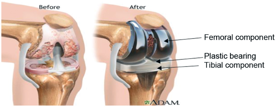
Worn-out bone and knee joint replacement. 3
For fabrication of an artificial knee joint, mechanical engineering comes to rescue. Usually, five- or seven-axes computerized numerical control (CNC) milling machine is employed to fabricate condylar joints made from high wear resistant, biocompatible, corrosion resistant, hard alloys like Ti-6Al-4V and ceramics. It results in deep milling marks or cusps, and lays are left behind. Appendix 1 gives an overview of the different types of materials used to make femoral components. Finishing of these kinds of components with sub-micrometer form accuracy and surface finish in the nanometric range is thought to be the most complex and difficult of all finishing processes. 4 Traditionally, robotic grinding and belt grinding have been tried to finish these orthopedic implants below 100 nm Ra value. To prevent contamination, tissue growth, and injury to muscle and to minimize friction, such a low surface finish is a stringent requirement. As far as fatigue life is concerned, it is the surface finish at the contact points that affects both performance and functional life of the implants. Smooth surface ensures that no contaminants can reside inside the contact surfaces. If surface integrity is not maintained then it would lead to a premature failure.
Charlton and Blunt 2 developed a new technique which has been adopted to polish freeform knee joint surfaces. The manufacturing path utilizes a seven-axes CNC Zeeko polishing machine to polish knee joint surfaces to the required form and finish improving the life time of the replacement. At Huddersfield, surface finish of Sa = 2.8 nm was realized in a knee joint section polishing automatically on a Zeeko IPR 200 machine. The machine uniquely uses an inflated bulged polymer polishing head or bonnet as the lap medium in combination with water-based polishing slurries. The key feature of the Zeeko polishing machine is an adaptive pressure-tool tuned automatically to the local surface irregularities. 4
In this study, abrasive flow finishing (AFF) has been employed to overcome the aforementioned drawbacks and limitations of the traditional finishing processes and to develop a novel finishing technique with high finishing rate (FR) and uniform surface finish. In this article, the work is focused only on the knee joint; however, this process can also be employed to finish other freeform surfaces used in engineering and medical arenas with a change in fixtures and process variables.
Mechanism of material removal in abrasive flow machining process
Abrasive flow machining (AFM, also called as AFF process) is mainly used in the defense, aerospace, mold, automobile, and other industries for finishing, deburring and sharp edge rounding, removing recast layer, and producing compressive residual stresses in a wide range of applications.5–9 Inaccessible areas and complex internal passages can be finished economically and effectively. The typical AFM (two-way flow) process uses two vertically opposed cylinders which extrude an abrasive laden semi-solid medium back and forth through the fluid circuit formed by the workpiece and the fixtures. 10 The workpiece and fixture are held between upper and lower cylinders, and the medium (homogeneous mixture of viscoelastic base material, abrasive particles, and additives) is encapsulated in the space between them. Under the presence of external force, the medium is extruded by the piston of the upper cylinder to pass through the passage between workpiece and fixture, to the lower cylinder. The workpiece surface in the passage is the surface to be finished. 11 The extrusion pressure, traveling length, and number of reciprocating cycles are controlled. 12
The fundamental principle behind the AFM process is to use a large number of random cutting edges with indefinite orientation and geometry. The extremely fine chips produced in AFM result in better surface finish and generation of more intricate surface features.13,14 The abrasive particles are held firmly in place at the contact point and the medium becomes a “self-deformable grinding stone” which adapts to the passage geometry. 15 Medium viscosity temporarily rises due to high restriction and returns to the normal value after the slug has passed that zone. 6 AFM is mostly used for finishing of internal surfaces. To finish an external surface, additional tooling is generally required to ensure that the flow gap between the external surface and the tooling is sufficiently tight for adequate abrasive action. 7 Large surface irregularities, such as deep scratches, out of roundness, lays, and large bumps, cannot be removed by AFM process because material is removed almost uniformly. 16
Furthermore, these prosthetics are made of very high-strength material (mentioned in Appendix 1). These joints are not hollow or thin. They are unlikely to deform under the influence of hydraulic pressure. The fixtures are made of EN8 mild steel and Teflon. These materials are weaker than workpiece. Even the fixtures did not deform, so the shape accuracy is ensured.
Literature survey
Jain and Adsul 17 carried out experimental research on AFF and concluded that the dominant process parameter is % concentration of abrasive, followed by abrasive mesh size, number of cycles, and medium flow speed. Gorana et al.18,19 reported that cutting force components and active particles’ density govern the surface roughness produced during AFF process. However, effect of medium temperature on AFF efficiency was not studied. The theoretical and experimental research of thermal properties of medium was carried out by Fletcher and Fioravanti. 20 Davies and Fletcher 21 experimentally found that viscosity of the medium is significantly affected by the medium temperature. Jain and Jain 22 also reported the effects of specific energy and temperature on AFF responses. They reported that the medium temperature increases with number of finishing cycles and extrusion pressure. They also found that both theoretical and empirical studies of AFF are greatly hampered by the inherent random nature and multiplicity of variables. The medium is non-Newtonian in nature, particles are randomly distributed and the entire process is encapsulated. The variables are interdependent which further complicates the studies. Thus, the material removal mechanism is only partially understood.
Jain et al. 23 and Jain and Jain 22 applied artificial neural network (ANN) approach to analyze the AFF process. They concluded that with the increase in number of cycles, material removal rate (MRR), which is comparatively high initially, decreases afterwards. Initially, the surface has sharp peaks, which are sheared more easily and become somewhat flatter than before. Further finishing of this flat surface would require higher tangential force, hence MRR decreases. Jain et al. 24 and Jain and Jain 25 applied finite element simulation approach to model AFM process to evaluate stresses and forces. Fang et al. 26 criticized their model by saying that abrasive particles are not only sliding but also rolling, which would reduce MRR. The shear thinning properties of the abrasive fluid can be determined using rheometrical devices as reported by Carreau et al. 27 Experimental results 25 showed that material removal is also governed by the initial surface finish and workpiece hardness. Based on two-body wear, they proposed their mathematical model which included operating parameters to explain wear in AFF process. However, theoretical results of surface roughness could not match very well with the experimental data. It can be found that the assumptions were somewhat over simplified and unrealistic because abrasive particles were assumed to be spherical in shape and wear process was assumed to be only cutting without plastic deformation. It was the first time to predict forces from rheological properties of the medium in AFM process when Gorana et al. 19 developed a two-body abrasive mathematical model to predict radial and axial forces on a single abrasive particle. It has been shown experimentally that material removal increases with piston pressure and is highly dependent on the force acting on the abrasive particles. 26 Bähre et al. 28 developed an in-process measurement set up in order to measure the influence of the applied medium pressure on the machined part of the workpiece with the help of an axial force sensor. Wang et al. 29 used computational fluid dynamics (CFD) simulation to find the optimal core shape for complex holes where uniform shear stress generates uniform surface roughness.
A freeform surface made of stainless steel (SS) similar to the actual knee joint was fabricated to investigate the viability and superiority of the AFF process. This process is thought to be an alternative finishing technique to the traditional time-consuming and costly belt grinding process. The novelty of the process is that it can simultaneously finish different surfaces of a product, contrary to the traditional techniques. The motivation was to find out the best process parameters in the prescribed range, an appropriate fixture design, and medium formulation. This will eliminate the stringent requirements of tool hardness/rigidity and defined cutting edge and address the problem of finishing difficult-to-machine sculptured surfaces. A comparative review of AFF process with other nanofinishing processes has been reported by Jain et al. 30
AFF system
Experimental set up
The main components of AFF system are AFF set up, fixture or tooling, and medium. AFF fixture or tooling guides the abrasive medium and holds the workpiece, which is placed in between the upper and lower medium cylinders. Uniform and sufficient gap between the workpiece and fixture helps the medium to achieve necessary uniform velocity while passing through the workpiece contour. Every workpiece needs its own clamp. The clamp is very important and it decides the AFF performance.31,32
Surface roughness will not be uniform when a complex hole is polished by AFF process. Wang et al. 29 reported that CFD numerical method can be used to design good passage ways to find the smooth surface on the complex hole in AFF process. Velocity, strain rates, and shear forces applied by the medium acting on the workpiece surface were computed using CFD approach, while keeping pressure as constant. Their results demonstrated that the desired shape of the mold core inserted into the hole results in uniform roughness on the surface.
In AFF process, it is possible to control and select the intensity and location of abrasion by appropriate fixture design. Two cylinders were fabricated to easily accommodate knee joint-spider assembly (Figure 2(a)), sealed and sandwiched between the pistons. Figure 2(b) shows a sectioned view of the spider and its dimensions. Mild steel (EN8) was chosen for fixture fabrication because of ease of fabrication and cost. The wall thickness should be sufficient to withstand large hydraulic pressure. Gaskets should be inserted between the cylinders to prevent medium leakage. Medium passage width is not uniform as shown in Figure 2(c) (for simplicity of the diagram, spider is not shown). The exploded view of the figure (in the side) shows chip formation, the forces acting on the knee joint, and abrasive particles.
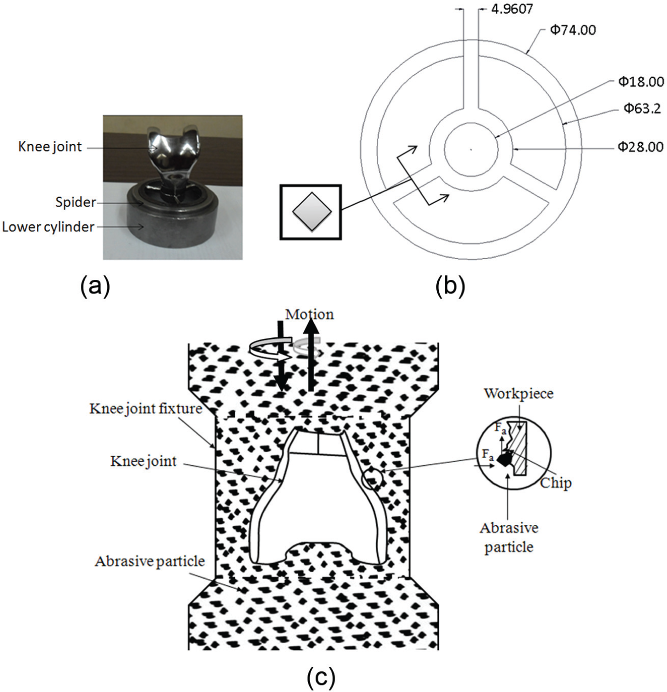
(a) Photograph of a knee joint held in a spider, (b) sectioned view of spider with dimensions, and (c) knee joint in the AFF set up.
One flywheel-shaped spider (Figure 2(b)) with three arms was fabricated by abrasive water jet cutting. It was designed so as to maintain a balance between strength and effective area available for the medium extrusion. Fixing knee joint ahead of the flow itself will reduce the effective area to a great extent. This axial obstacle offered by the projected area of workpiece (knee joint) will increase load on the spider and pistons. So, the spider material should have high bending and shear strength. SS is a good choice. The spider has a central hole where knee joint is held by means of a bolted joint (Figure 2(a)). The dimensions are shown in the schematic diagram (Figure 2(b)). The thickness of the spider is 5 mm. The entire assembly is held between the lower and upper cylinders. The edges of the ribs were rounded off for smooth flow of medium and to minimize pressure loss due to separation.
Medium formulation and preparation
Important part of a successful AFF system is medium. The medium loses its finishing capability with time due to fracture and wear of abrasive particles and mixing of the removed workpiece material with the medium. Commercial medium contains polyborosiloxane or silly putty as base carrier; diamond, boron carbide (B4C), or silicon carbide (SiC) as abrasive; and some additives/plasticizers. Base carrier also acts as a binder for abrasives and transmits force from the piston to the abrasives.
Actual prototype of knee joint is made of Ti-6Al-4V, which is harder than SiC and B4C as shown in Table 1. A SS knee joint was fabricated for the present investigations. SiC (mesh sizes 1000, 1500, and 2000) was used as abrasive because it is harder than SS. The medium is made by mixing silicone oil, boric acid, polydimethylsiloxane (PDMS), and other additives. This non-Newtonian pseudo plastic fluid shows unusual properties under different ranges of strain rate. It is a viscoelastic fluid. Silly putty can be characterized as a shear thickening fluid. High elasticity helps abrasives indent deep and high viscosity helps retaining the abrasive particles intact against shearing of the workpiece surface protrusion. High viscosity medium is required to finish large internal passage or external contour, and very low viscous slurry type medium is needed for micro channel and nozzle-type workpiece. Viscosity can be increased either using high viscous polymer or by increasing percentage of abrasives. 33
Hardness and density of some abrasives and workpiece materials.
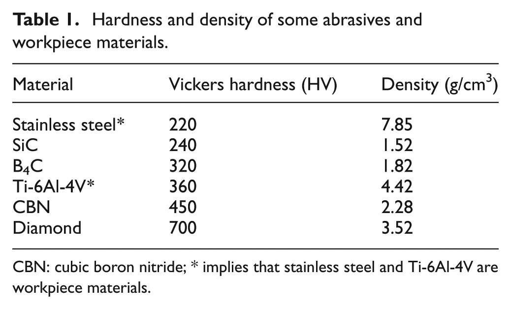
CBN: cubic boron nitride; * implies that stainless steel and Ti-6Al-4V are workpiece materials.
The polymer used is mainly elastic in nature. But for high FR, high viscosity is essential. Miscibility of abrasive in polymer is low. Plasticizer or softener is mixed to achieve the desired medium properties, that is, easy flow ability. These are low molecular weight and low viscous compounds, which get mixed with the polymer and increase softness. Silicone oil, naphthenic oil, toluene, varnish oil, and hydrocarbon oil can be used as plasticizer. They diffuse in between the polymer chains and increase the distance between the chains. It reduces cohesive force and internal friction of polymer chains.
For the present investigation, multigrade hydrocarbon oil was used because of its compatibility with silly putty. Its content should not be very high as the medium becomes oily and sticky. The plasticizer develops a very thin protective coating on the workpiece surface, which prevents interaction between abrasives and workpiece surface. Most widely used mold releasing agent, namely, zinc stearate, is used as an additive to exploit its non-sticky and lubricating properties. It reduces plasticizer requirement to a great extent, and thus, oiliness is avoided. It also reduces brittleness of the medium and develops a continuous mass.
The mixing of the ingredients is done using two-roll mills (150 mm diameter rolls, 7.5 HP motor) in the temperature range of 40 °C–55 °C. The mixing is carried out as per ASTM D 3182-89 with mastication, which means breaking down of molecular chains of polymer. This is very necessary because it improves homogeneity and acceptability of polymer for abrasive particles. 34 The impact of abrasive percentage on polishing efficiency is paramount, but with the increase in abrasive percentage, the flow ability of the medium diminishes. 18 That is why, a maximum ratio of SiC/Silly putty = 55:45 (by weight) is chosen.
Experimentation
Plan of experiments
AFF is influenced by a number of parameters but in this work only pressure was varied to make preliminary study about feasibility in nanofinishing of knee joints using AFF process to compare the finishing time required and uniformity of finishing across the face as well as different faces. The pressure was varied at 20, 22, and 24 bars. At first, 1000 mesh size abrasive was chosen and the medium with SiC/Silly putty level = 50:50 was carefully prepared with other additives. Three experiments were conducted each for 1500 cycles with 20, 22, and 24 bar pressure. Then, the composition of the SiC/Silly Putty was changed to 55:45 ratio.
Measurement of surface finish
Measurement of the surface finish of freeform surface is as difficult as finishing it. One swiveling device was chosen which can hold as well as tilt the workpiece to make the area of the surface under investigation horizontal. A linear tactile probe SurfTest SV-2100M4 was used to measure surface roughness of the knee joint. The roughness is measured in the direction perpendicular to the finishing direction on the same point before and after finishing experiments. Initially, the idea was to measure roughness at 10 points per face. But it was not possible to measure where the surface has slope in multiple directions because sufficient approach length and evaluation length were not found. It is difficult to align a three-dimensional (3D) curved surface horizontally by manual control. The measurements at those points were not repeatable and erratic in nature. So, the points only on simple curved areas were chosen. The exact location of the point of measurement is identified with the help of a transparent template prepared for this purpose. In these experiments, the final surface roughness (Ra) value of the previous experiment becomes initial surface roughness (Ra) value for the next experiment. Special optical profilometer, software control, and tilting mechanism are needed for reliable and accurate measurement of freeform surfaces. Tactile probe is not able to follow ups and downs and contour of freeform surface. However, the only alternative seems to be feasible is to measure the surface roughness variation in both directions (X and Y) and compare it with the original (i.e. before finishing) values of surface finish in X- and Y-directions. Atomic force microscope (AFM) image was taken only on plane surfaces because of sensitivity and limitation of the instrument; 25 × 25 µm2 area was chosen for the investigation.
The preliminary experiments were conducted to study the effect of extrusion pressure on % change in Ra and FR. % Change in Ra is calculated as {(ΔRa/initial Ra) × 100}, where ΔRa = (initial Ra − final Ra). Here, Ra is centre line average (CLA) surface roughness measured in micrometers. FR (nm/min) is calculated as {(ΔRa/finishing time in min) × 1000}. The initial and final surface roughness of each part is measured by SurfTest machine.
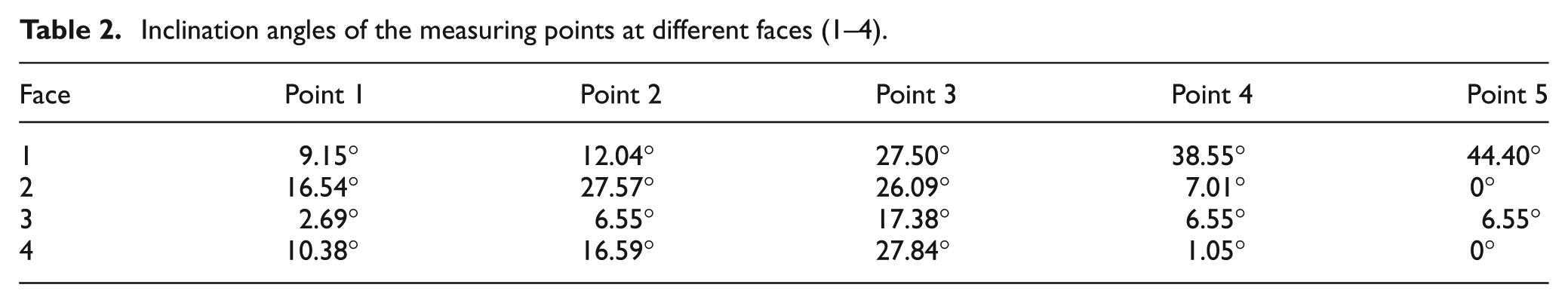
The coordinates of the points were measured on a CNC machine. Tangents were drawn (as shown in Figure 3) in the solid model of the knee joint by SolidWorks software at the identified points, and the angles of inclination (θ) were evaluated (Table 2). Then, the knee joint was held in a vice where there is a provision to tilt the knee joint at the desired angle (θ). The knee joint was tilted to the opposite of the corresponding angle to align it horizontally.
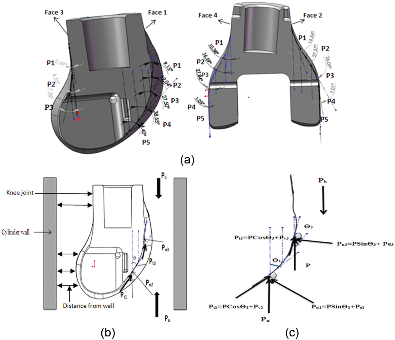
(a) Inclination of identified points, (b) force acting on the convex workpiece surface and distance of the workpiece surface from the fixture or cylinder wall, and (c) free body diagram of forces acting on face 1.
Inclination angles of the measuring points at different faces (1–4).
Results and discussion
Best results of surface roughness measurements and topography are shown in Figures 4 and 5, respectively. Initial and final surface roughness on each face on a certain point with corresponding surface roughness reduction ratio is shown in Figure 4. It is clearly seen that significant reduction (>72%) has been achieved. However, optimization of the process parameters would result in a higher % ΔRa. Topography was taken by atomic force microscope on flat surfaces (faces 2 and 4) only. Figure 5 shows the initial and final surface topography.
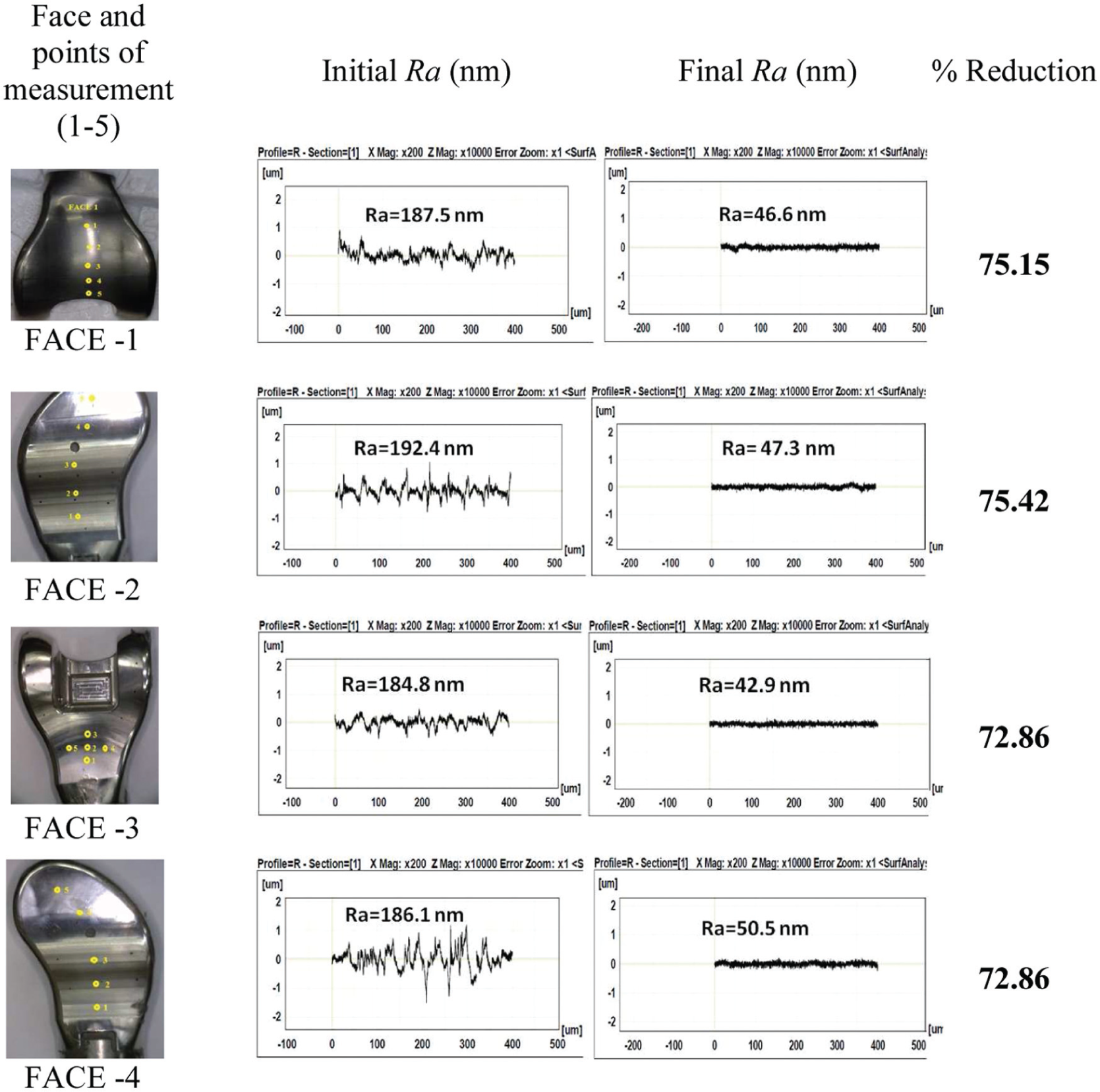
Different faces of a knee joint, initial surface roughness, final surface roughness, and % reduction in Ra. Finishing conditions are mesh size of 1500, SiC:Silly Putty = 55:45, and pressure = 24 bar.
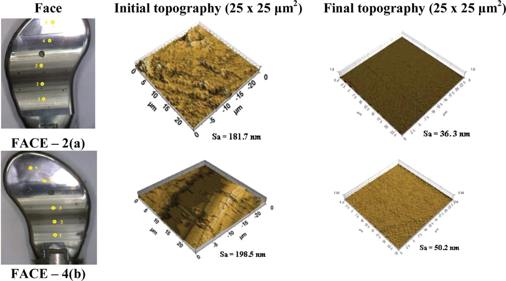
Initial and final surface topography measured by atomic force microscope for two faces, faces 2 and 4. Finishing conditions are mesh size 1500, SiC:Silly Putty = 55:45, and pressure = 24 bar.
The effects of different process parameters on the responses (% change in Ra, FR, final Ra) have been discussed in the following sections. There are four faces of the knee joint. For each face, surface roughness value was measured at 5 points. However, for comparison purposes, surface finish only at three critical points (i.e. at different angles) was considered. Variation in Ra value on all the three points with a variation in pressure has been considered.
Inclination angle
Knee joint is a complex type of freeform surface. It has slope in multiple directions which complicates finishing as well as measurement procedure to a great extent. The inclination angle (θ) (shown in Figure 3(b)) is the angle between the vertical direction and the tangent drawn at the point under consideration in the same plane (XY, XZ, or YZ). The tangents were drawn in the solid model of knee joint by SolidWorks software. Pu is the hydrostatic force acting toward the upper cylinder and Pb is the hydrostatic force acting toward the bottom cylinder (Figure 3(c)). They are assumed to be equal and denoted by P. Due to curvature, the extrusion force is resolved into shearing force (P.Cosθ, responsible for shearing the surface protrusions) and normal force (P.Sinθ, responsible for abrasive indentation). Viscoelastic nature of the fluid imparts viscous force Pv (acting tangentially to the surface) and elastic force Pe (acting perpendicular to the surface). Thus, the total tangential force is given by Pt = P.Cosθ + Pv. The total normal force is given by Pn = P.Sinθ + Pe.
Almost full abrasion force (P.Cosθ) is acting where the angle θ is low. Only a part of the abrading force is available for shearing where the angle θ is high. The normal force (P.Sinθ) is high where the angle (θ) is high. It is the P.Sinθ and elastic force Pe exerted by the medium, which is responsible for indentation. However, this will be quite different when the medium is flowing in the reverse direction due to the asymmetry of the knee joint. Finishing conditions favorable during, say, upper stroke may become adverse in the reverse stroke. If the shearing force available is not enough at higher depth of penetration, then the abrasive particles may roll without cutting. 35 Due to rotation of the abrasive particle, the depth of indentation is decreased. The abrasive particle may then become able to shear the workpiece material depending upon the value of the shear force acting on it.
Depending upon the inclination angle, the final Ra, % ΔRa, and FR vary as shown in Figure 6. These results can be interpreted as follows:
As the pressure increases, shearing force also increases. But temperature of the medium also increases due to abrasion and internal friction. As a result, viscosity decreases as shown in Figure 7. This figure clearly shows that with an increase in temperature, the medium loses its viscosity; hence, the abrasive holding capacity against shearing reduces. These results (Figure 7) pertain to the medium used in this work. Effect of temperature on the efficiency of AFF process has been studied by other researchers also.36,37
The same knee joint is finished again and again. This resulted in gradual improvement in surface roughness, that is, lower decrease in final Ra value. It becomes difficult to finish the already finished surface because the surface asperities had already become blunt/flat, hence it requires larger force in each cycle. Finally, it moves toward attaining critical surface finish. So, the % change in Ra (Figure 6(b)) and FR (Figure 6(c)) also decreased with an increase in the angle of inclination.
If the medium is passing through a convex surface, it abrades the workpiece surface better as compared to the case if it follows a concave surface. The medium while finishing face 1 of the knee joint experiences both increasing and decreasing slope while moving in two opposite directions, that is, it is like a saddle (Figure 6(d)). % ΔRa (Figure 6(b)) and FR (Figure 6(c)) decrease when the inclination angle (θ) increases. As the angle θ increases, the penetrating force increases (P.Sinθ), but the shearing force decreases (P.Cosθ). As a result, the rate of % change in Ra and FR decreases. It is visible from Figure 6(a) that the rate of change in final Ra is also changing but at a reduced rate.
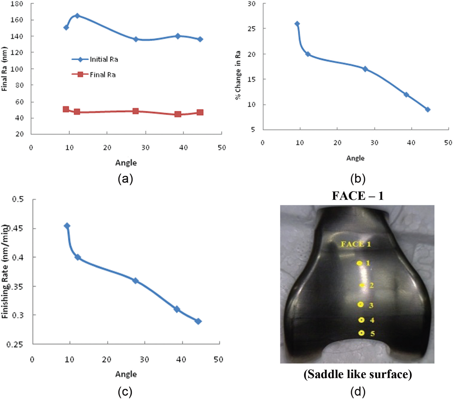
Effect of inclination angle on (a) final Ra, (b) % change in Ra, and (c) FR for face 1. Finishing conditions are mesh size 1500, SiC:Silly Putty = 55:45, pressure = 24 bar, and (d) saddle-like surface on face 1.
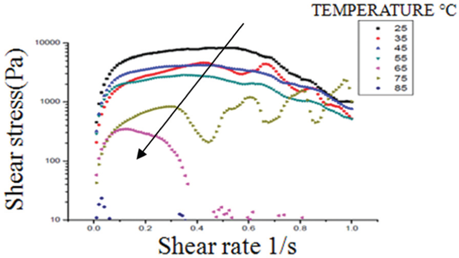
Shear stress versus shear rate at different temperatures. Highest peak showing yield stress.
Extrusion pressure
Final Ra
The pressure and velocity of the extruding medium are important factors for AFF performance. The medium flow velocity is governed by the pressure, passage geometry, and medium rigidity/viscosity. Enhancing extrusion pressure increases medium flow velocity. The smaller is the width of the passage, the bigger is the extruding pressure required. 31 Higher extrusion pressure increases normal and axial forces on abrasive particles. As a result, abrasive particles indent to a greater depth and shear workpiece protrusions with more volume. It also increases number of active abrasive particles interacting with the workpiece (knee joint) effectively. A minimum or threshold pressure is necessary for piston movement. But increase in pressure beyond a limit may reduce MRR and result in plowing or smearing of workpiece. At greater indentation depth, if shearing force required to cut protrusions on the workpiece is higher than the available force, then the abrasive particles will roll rather than cut. 35 There is also a danger of fixture failure and medium leakage at very high pressure. The medium may actually yield as a result of severe shearing. Then, it becomes a gel-like fluid, and it is not able to hold abrasive particles firmly against abrasion.
Effect of pressure variation on the final surface roughness (Ra) obtained is shown in Figure 8(a). Final Ra is decreasing with increase in pressure because abrasive can remove asperities more effectively at higher pressure. As the pressure increases, the workpiece asperities experience more aggressive shearing; hence, final Ra value goes down. This behavior is experienced at all the four faces of the workpiece (Figure 8(a–d)).
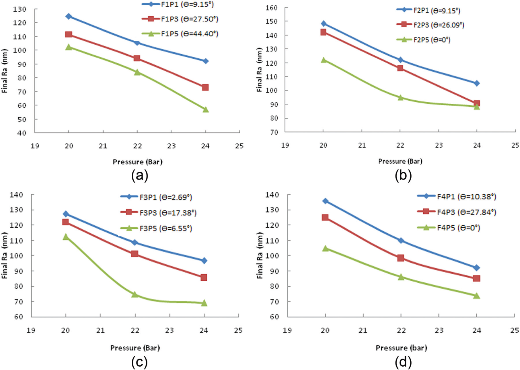
Effect of pressure variation on final Ra (a–d) (F stands for face, θ for inclination angle, and P stands for a point on that surface). Finishing conditions are mesh size 1500, SiC:Silly Putty = 55:45, and pressure = 20, 22, 24 bar.
% change in Ra
The % ΔRa value decreases with increasing pressure for all the four surfaces. However, Figure 9 shows the results only for faces 1 and 3 which have more complex surfaces than those of faces 2 and 4. As the pressure increases, more amount of work is done by the abrasive particles. Hence, more heat is produced which decreases the medium viscosity, that means the abrasive holding strength of the medium goes down. It results in decrease in % ΔRa with increase in pressure. The effect of rise in temperature on shear strength of the medium for a given shear rate is shown in Figure 7. It shows a substantial decrease in shear strength of the medium with an increase in temperature. It also means that lower pressure is exerted in the direction normal to the workpiece surface.
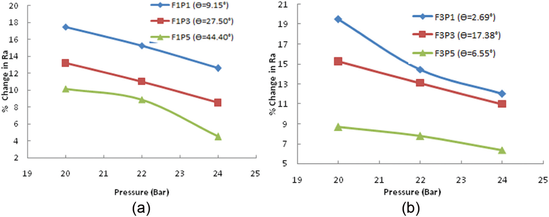
Effect of pressure variation on % change in Ra (a) for face 1 and (b) for face 3 (F stands for face, θ for angle, and P for point on that surface). Finishing conditions are mesh size 1500, SiC/Silly putty = 55:45, and pressure = 20, 22, 24 bar.
Finishing Rate (FR)
The effect of extrusion pressure on FR for faces 1 and 3 is given in Figure 10. The FR decreases with an increase in pressure (Figure 10) which can be explained as was explained in the case of final Ra and % ΔRa. With an increase in pressure, the medium viscosity decreases due to an increase in the medium temperature, hence FR decreases. According to Preston’s equation, FR is proportional to the force acting on abrasive particle and its velocity. The apparent violation of Preston’s law is attributed to drastically reduced viscosity at higher temperature. The medium becomes a gel-like substance at higher temperature. The medium pressure increases but the pressure imparted on the abrasive particle while interacting with the workpiece surface reduces. The viscosity is not sufficient enough to hold the abrasive particles against the normal and shear forces required to remove material from the workpiece surface. As a result, the FR decreases with an increase in pressure. 35
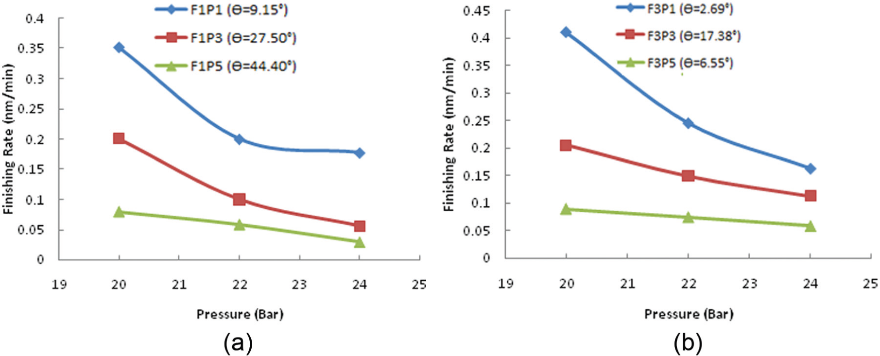
Effects of pressure variation on FR (a) for face 1 and (b) for face 3 (F stands for face, θ for angle, and P for point on that surface). Finishing conditions are mesh size 1500, SiC:Silly putty = 55:45, and pressure = 20, 22, 24 bar
Distance from the fixture wall
Surfaces of the knee joint far away from the fixture wall do not undergo severe shearing as compared to the surfaces where the gap is smaller. To check this, some points were colored on the knee joint before the test run and checked after the finishing was over for a short period. The color spots were intact only where the gap is large. In most of the cases, larger the distance from the wall, larger is final Ra (Figure 11(a)). It can be attributed to the smaller value of force acting on the knee joint in that area because of larger cross-sectional area through which the medium is flowing. The viscosity temporarily rises in the areas of larger restriction (or smaller distance from the fixture wall). The large elastic and viscous components of force abrade the knee joint more aggressively. The reverse argument holds true for the smaller restriction (or larger distance from the wall). In total, 1500 cycles were fixed for each test run. Surface finish at the site of the greatest restriction was marginally better as compared to the sites away from the wall (Figure 11(a)). Figure 11(b) shows that the % ΔRa decreases with an increase in the distance of the workpiece surface from the wall of the cylinder (or fixture). Sites, where the gap is the least, were finished comparatively faster because of higher forces acting in that zone. Figure 11(c) shows that the FR decreases as the distance from the wall increases, due to lower forces acting on the workpiece through the abrasive particles. In view of the trends shown in Figure 11(a) and (b), the FR decreases (Figure 11(c)) with an increase in the distance of the workpiece surface from the fixture wall.
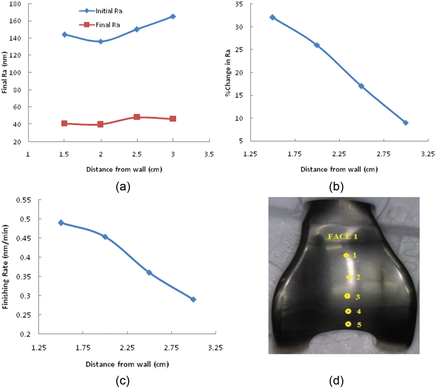
Effect of distance from the wall on (a) final Ra, (b) % change in Ra, and (c) FR. (d) The location of measuring points. Finishing conditions are mesh size 1500, SiC:Silly Putty = 55:45, and pressure = 24 bar.
Cleaning of the knee joint
The knee joints should be cleaned by acetone to remove any traces of chemicals/foreign particles on the surface. Ultrasonic cleaning should also be done. Mass spectroscopy and X-ray diffraction (XRD) can be done to ensure that no residue is there. It is very much unlikely that any particle will remain embedded to the surface of hard metals like Ti-6Al-4V. If such particles remain embedded in the knee joint then they will definitely be harmful and would create discomfort to the patient. No such post-operative trouble/physiological imbalance can be related to abrasive flow machined prosthetics. Almost same abrasives are used by the traditional finishing techniques also. The polymers and other additives used are not known to be toxic.
Comparison of AFF with magnetorheological abrasive fluid finishing and rotational magnetorheological abrasive fluid finishing processes
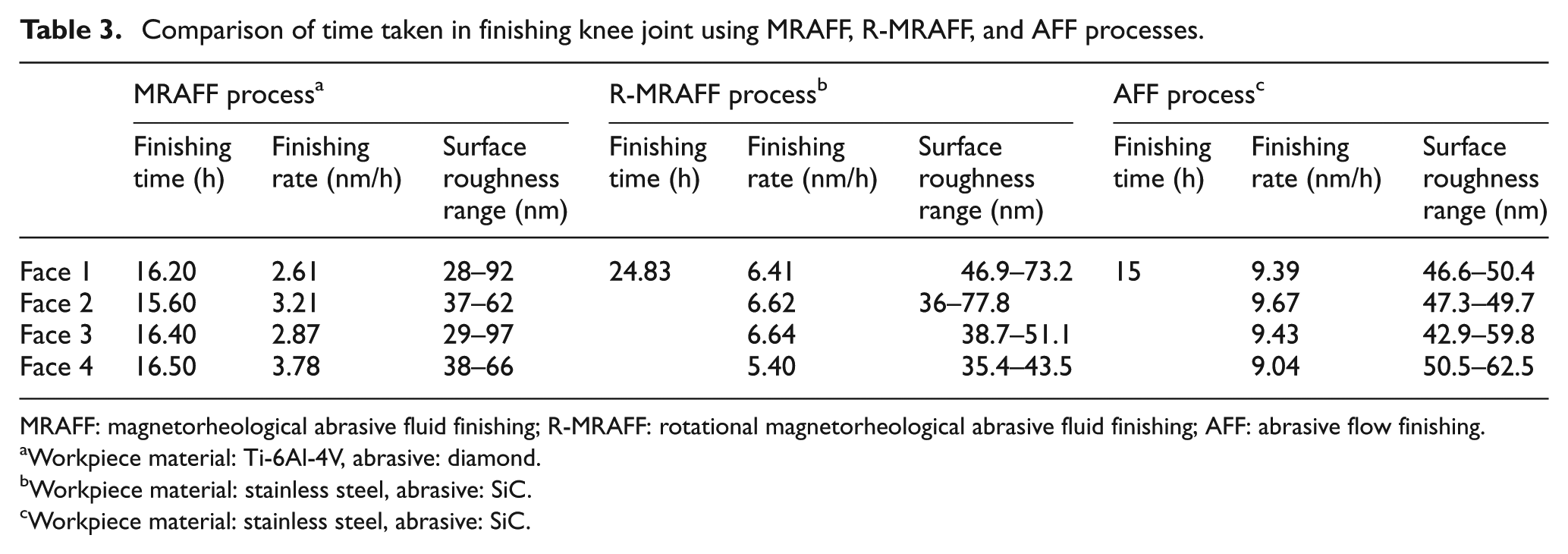
Jain and Sidpara 38 tried raster finishing in a three-axes CNC milling machine by magnetorheological abrasive fluid finishing (MRAFF) process (ball end tool with magnetorheological (MR) fluid brush (Figure 12)), but it was taking on an average time of 16.4 h per face for finishing of titanium alloy (Ti-6Al-4V) knee joint. The total finishing time for all the faces in MRAFF process was 64.7 h even after using diamond abrasive. The rotational magnetorheological abrasive fluid finishing (R-MRAFF) process has been applied by Satish Kumar 39 to reduce the finishing time significantly by finishing all the faces simultaneously. The total finishing time was reduced to 24.83 h with SiC abrasive as given in Table 3. He reported that this one-shot finishing process (Figure 13) can be further enhanced using harder abrasive particles like cubic boron nitride (CBN) or diamond and by applying uniform magnetic field.
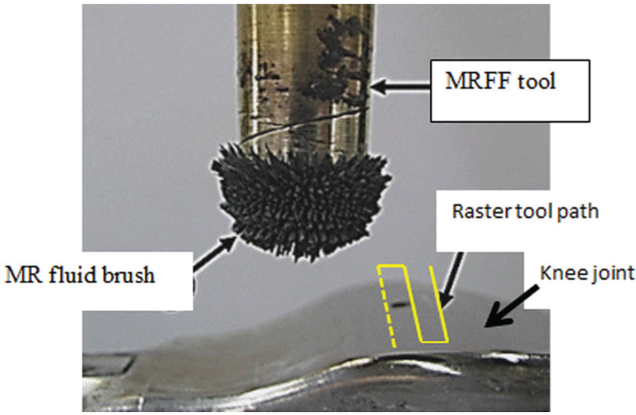
MR fluid brush used for finishing knee joint. 38
Comparison of time taken in finishing knee joint using MRAFF, R-MRAFF, and AFF processes.
MRAFF: magnetorheological abrasive fluid finishing; R-MRAFF: rotational magnetorheological abrasive fluid finishing; AFF: abrasive flow finishing.
Workpiece material: Ti-6Al-4V, abrasive: diamond.
Workpiece material: stainless steel, abrasive: SiC.
Workpiece material: stainless steel, abrasive: SiC.
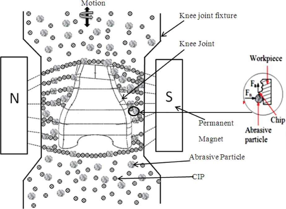
Schematic of MRAFF process. 39
The comparison in Table 3 cannot be concluded unless workpiece material, finishing conditions, and initial surface roughness values are exactly same in all the three cases. However, comparison between R-MRAFF and AFF is somewhat rational because of the same workpiece and abrasive particles. The above comparison clearly shows that AFF is a better process in terms of FR. In MRAFF process, the force acting on individual abrasive particle is low. In R-MRAFF process, the medium is viscoplastic and viscosity is quite low as compared to AFF medium. That is why the extent of abrasion is low in those two cases but final surface finish is mirror like. Rotation given to the magnetic field in R-MRAFF increased the interaction length of abrasive particles to a large extent. Non-uniform working gap has led to different FRs at different locations on different faces. It is expected that designing a better passage way using CFD, and temperature control of the medium during the process, would result in still higher FR.
Conclusions
A workpiece similar to the knee joint implant was finished by AFF. The following conclusions can be drawn from the present investigations:
Surface finish ranging from 42.9 to 62.5 nm has been achieved at various locations which are within the recommended ASTM standard of knee joint prosthesis (≈100 nm). Such a good surface finish varying in a narrow range over the full knee joint would result in better durability, superior tribological properties, and higher performance of artificial knee joint. This will reduce wear rate and enhance the implant useful life.
CFD simulation should be done for the better passage way or fixture design so that almost equal FR could be achieved at different locations on different faces. The use of an inverse and extended replica with some pre-specified gap as a fixture is suggested so that the uniform velocity hence uniform surface finish can be achieved.
AFF process is able to finish all the four faces at the same time with comparatively higher FR, and hence, taking lesser time of finishing.
Medium temperature control is the key to success. It has paramount effects on performance of the medium.
Footnotes
Appendix
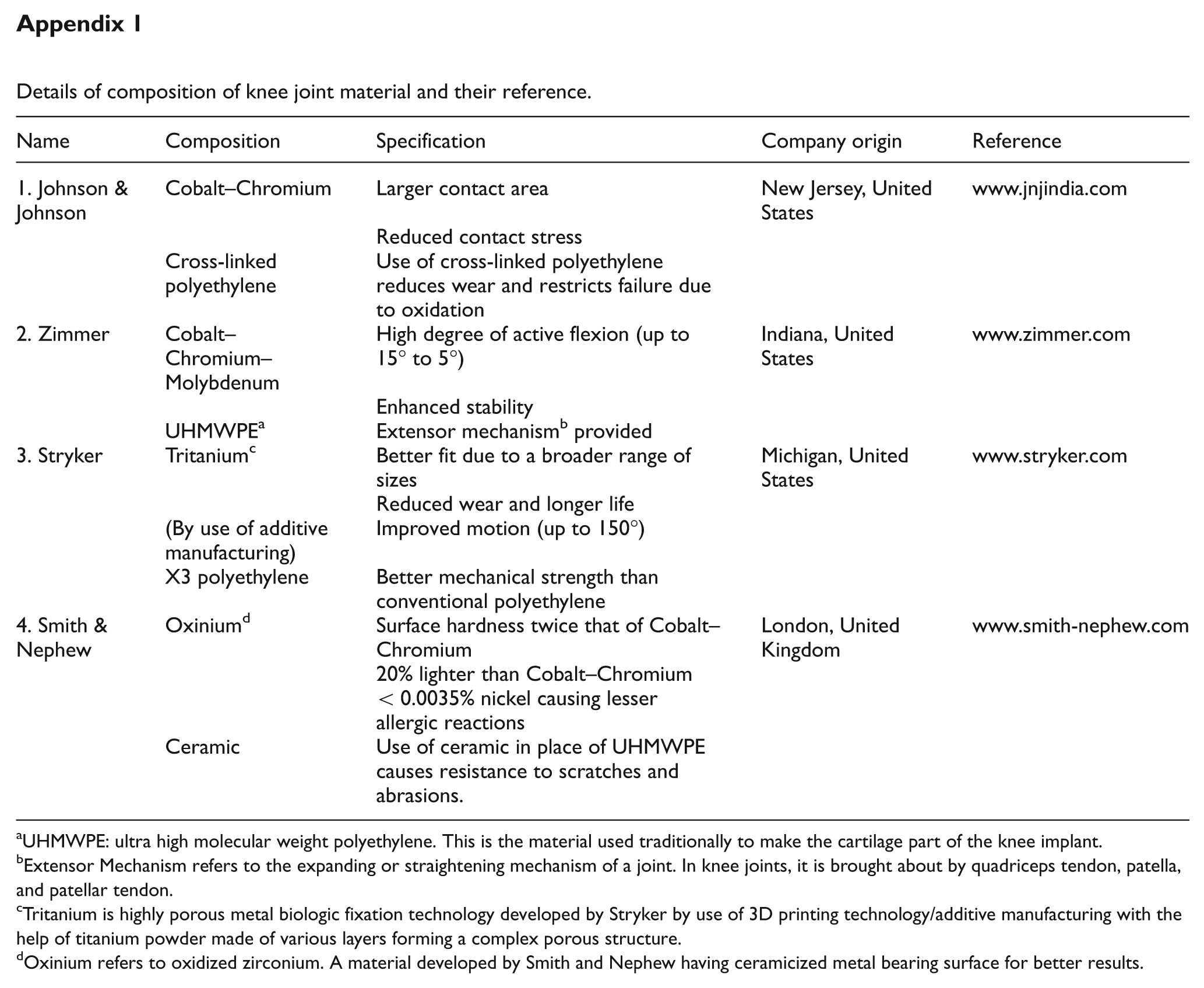
Details of composition of knee joint material and their reference.
| Name | Composition | Specification | Company origin | Reference |
|---|---|---|---|---|
| 1. Johnson & Johnson | Cobalt–Chromium | Larger contact area | New Jersey, United States | www.jnjindia.com |
| Reduced contact stress | ||||
| Cross-linked polyethylene | Use of cross-linked polyethylene reduces wear and restricts failure due to oxidation | |||
| 2. Zimmer | Cobalt–Chromium–Molybdenum | High degree of active flexion (up to 15° to 5°) | Indiana, United States | www.zimmer.com |
| Enhanced stability | ||||
| UHMWPE a | Extensor mechanism b provided | |||
| 3. Stryker | Tritanium c | Better fit due to a broader range of sizes | Michigan, United States | www.stryker.com |
| Reduced wear and longer life | ||||
| (By use of additive manufacturing) | Improved motion (up to 150°) | |||
| X3 polyethylene | Better mechanical strength than conventional polyethylene | |||
| 4. Smith & Nephew | Oxinium d | Surface hardness twice that of Cobalt–Chromium | London, United Kingdom | www.smith-nephew.com |
| 20% lighter than Cobalt–Chromium | ||||
| <0.0035% nickel causing lesser allergic reactions | ||||
| Ceramic | Use of ceramic in place of UHMWPE causes resistance to scratches and abrasions. |
UHMWPE: ultra high molecular weight polyethylene. This is the material used traditionally to make the cartilage part of the knee implant.
Extensor Mechanism refers to the expanding or straightening mechanism of a joint. In knee joints, it is brought about by quadriceps tendon, patella, and patellar tendon.
Tritanium is highly porous metal biologic fixation technology developed by Stryker by use of 3D printing technology/additive manufacturing with the help of titanium powder made of various layers forming a complex porous structure.
Oxinium refers to oxidized zirconium. A material developed by Smith and Nephew having ceramicized metal bearing surface for better results.
Acknowledgements
Authors acknowledge the help of Mr Sanjeev K. Verma of Manufacturing Science Laboratory, IIT Kanpur, during the fabrication of the set up and conducting the experiments. Authors also acknowledge the help of Dr Nadeem Faruqui of Ortho Center Kanpur and Mr Nabeel Faruqui of Jaypee University of Engineering and Technology, Raghogarh (India) in preparing Appendix 1.
Declaration of conflicting interests
The author(s) declared no potential conflicts of interest with respect to the research, authorship, and/or publication of this article.
Funding
The author(s) disclosed receipt of the following financial support for the research, authorship, and/or publication of this article: This work was supported by Bhabha Atomic Research Centre (BARC), Mumbai (project no. BARC/Works/MoU/321/2011/), and the Council of Scientific and Industrial Research (CSIR) New Delhi, India (project no. 22(0479)/09/EMR-II).