
Abstract
The freeform complex surfaces have become an inevitable part of many components to perform specific functions. Many of these components require nanometer surface roughness to meet specific requirements in their application domain. Therefore, finishing operation as a final operation is necessary for such components. A magnetorheological fluid-based finishing tool is developed for finishing knee joint implant, which has complex freeform surfaces. Different types of magnetorheological fluids and various finishing steps are proposed to reduce finishing time. Surface characteristics of the knee joint implant are studied using a surface roughness measuring instrument and atomic force microscopy before and after finishing. A significant reduction in surface roughness (the best final surface roughness value obtained = 28 nm) is observed on the component after finishing. The surface roughness obtained on different surfaces is well within the values recommended in the ASTM standard for total knee joint prosthesis.
Introduction
Components having freeform surfaces (surfaces that cannot be defined accurately mathematically) have been widely used in aerospace, automobile, medical, consumer products, and die/mold industries to meet specific requirements. Many molds/dies and medical components, such as knee or hip joint implants, have complex three-dimensional (3D) surfaces. The first major concern of these components is the selection of a right kind of manufacturing process, and the second is the selection of an appropriate finishing process to achieve the required surface roughness.
Complicated 3D surfaces are generally made by processes such as casting, molding, or computer numerically controlled (CNC) milling. However, in the case of casting and molding processes, mold or pattern is prepared by CNC milling. Therefore, three- or five-axes CNC machines have been most widely used in machining freeform surfaces. Lasemi et al. 1 have given a state-of-the-art review on the recent research and developments in machining of freeform surfaces by CNC technology. The major issues such as tool path generation, tool orientation identification, and tool geometry selection that affect the final quality of the freeform surfaces have been discussed.
Finishing of these components is as equally important as their manufacturing. The fabrication of the components for many applications requires form accuracy in sub-microns and surface roughness in the nanometer range. Therefore, nanofinishing is an emerging technology for the fabrication of high-precision and high-quality freeform surfaces. The quality of the final finished surface significantly depends on appropriate selection of process. It has been reported2,3 that 37%–50% of the total time required to manufacture a die or mold is spent in finishing operations.
Previously, the finishing of workpieces having freeform surfaces was mostly carried out manually owing to a lack of automation, and unavailability of efficient process that could finish these components up to the desired level. Furthermore, manual finishing is costly, tedious, inaccurate, labor intensive, and time consuming, and it relies mainly on the worker’s skill. Therefore, the need for automating the polishing process for freeform surfaces has become the most important issue to increase productivity and quality. With advancements in metrology and computerized control, mechanization and automation of polishing processes can be achieved for high quality and productivity of the components that have 3D complex surfaces.
Many researchers have developed experimental set-ups for finishing of different sizes and shapes of the freeform components. A three- or five-axes CNC milling machine is used for final finishing of freeform surfaces. 4 It has been reported that a more uniform surface finish is achieved in cases of five-axes, as compared with three-axes milling, when all the machining parameters are the same in both cases. A force-controlled orbital head is also developed for finishing freeform surfaces. 5 In this technique, finishing is performed in steps that consist of many polishing methods, starting from grinding (1st step) to finally polishing with a felt pad (6th step). Researchers have used felt tool buffs with diamond paste for finishing freeform surfaces in steps. 6 In each subsequent step, the size of the diamond particles decreases so that finer finish can be achieved. The finishing of die steel surface is performed by a disc sander that is attached to a CNC machining center. 7 The major problem in this technique is the wear of the disc sander.
Finishing of a curved surface is also performed with a tool made of thermosetting polyurethane elastomer with a coating of aluminum oxide abrasives. 8 The tool is attached to a three-axes milling machine and it deforms itself in conformity to the shape of the work surface. However, the tool life is around 80 min owing to wear as well as detachment of abrasive particles.
A commercial product called ‘Precessions’ (Zeeko Ltd, UK) is also used for finishing spherical and aspheric surfaces. 9 A semi-spherical tool finishes the workpiece in the presence of polishing slurry. The polishing tool is hosted by a seven-axes CNC polishing machine that has been custom-designed. The finishing tool comprises an inflated, bulged rubber membrane of spherical form (the ‘bonnet’), covered with a non-pitch flexible polishing surfaces. The ball burnishing is also used for finishing freeform surfaces of plastic injection molds where the tool is attached to a CNC milling machine. 10 Some researchers have also used a form grinding process where the shape of the grinding wheel is an inverse replica of the workpiece to be finished. 11 However, such a technique is very specific for certain type of workpieces, hence it does not have flexibility in terms of the shape of the component. Researchers 12 have also used a CNC grinding center (GC) to finish the freeform surface. In this work, an elastic ball-type tool is developed that can be fitted to the tool post of the GC.
Apart from the above processes, a magnetorheological fluid-based finishing (MRFF) process in association with a computer control system has lot of potential to be used for the polishing of freeform surfaces owing to its flexibility, determinism, and efficient control over the abrading forces acting on the workpiece. Many researchers have developed different set-ups for finishing complex surfaces. However, the process mechanism remains almost the same in these processes.
Tricard et al. 13 developed magnetorheological (MR) jet finishing for finishing inaccessible areas of glass and single crystal. This process is suitable for finishing concave surfaces. However, this process may not be suitable when the initial surface roughness is high (∼300 nm or more) and the workpiece material is hard. Kim and Noh 14 developed a magnetic polishing technology to finish freeform surfaces (die and mold) using two types of polishing tools. One is an abrasive wheel type and the other is a magnetic brush type. In the first step, the abrasive wheel is used for polishing the initial rough surface to decrease the initial roughness value to a somewhat lower range. While in the second step, a magnetic brush tool is used for fine polishing to produce a mirror-like surface. A two-stage polishing experiment using a GC#400 wheel and magnetic abrasives on the curved surfaces of mild steel having an initial surface roughness of 640 nm (Ra) was performed, and the final roughness 90 nm (Ra) was obtained. However, the size and configuration of the set-up is such that it is very difficult to finish surfaces having a large curvature.
Singh et al. 15 developed a ball-end MR finishing tool for finishing 3D surfaces. In this set-up, an electromagnet is used to generate a magnetic field and MR fluid is supplied through the core material of the electromagnet coil. It is observed that in case of ferromagnetic material, the variation of magnetic flux density at the tip of the MR finishing tool is visualized similar to the ball-end cutter of a CNC milling machine, while in the case of non-magnetic materials, the magnetic lines of force do not pass through the workpiece and it does not make a very good shape of the ball-end MR polishing fluid. Hence, the set-up reported in Singh et al. 15 is claimed to be more suitable to finish magnetic materials. A final surface roughness of 70 nm from 414 nm is achieved on a flat EN 31 workpiece after 100 min. A copper groove is also finished from a 337 nm surface roughness to 102 nm after 60 min. However, no results are reported related to the finishing of complex 3D components in this reference.
From the literature survey, it is found that a MRFF process has the potential to finish complex freeform surfaces to nanometer surface roughness value. Therefore, it was envisaged to take advantage of the MRFF technique and explore further possibilities to develop a tool that can finish freeform surfaces irrespective of its size, shape, and hardness. A MRFF tool is developed for finishing complex freeform surfaces. A knee joint implant is finished, which has complex freeform surfaces. The surface roughness of a knee joint implant has a significant influence on the force of the connection and the reaction of tissues in the joint area between bone and implant, and even on the behavior of germs in the bone tissues. 16 Different types of MR fluid are prepared and used for finishing. A stepwise finishing is proposed to enhance finishing rate (i.e. rate of change of surface roughness value with time).
MRFF process
The main component of MRFF process is MR fluid, which consists of magnetic carbonyl iron particles (CIPs), non-magnetic abrasive particles, water/oil, and some additives. MR fluid behaves like a Newtonian fluid in the absence of a magnetic field. MR fluid gets stiffened and it behaves like a viscoplastic fluid under a magnetic field owing to the creation of chain-like structures of CIPs by aligning along the magnetic flux lines. The abrasive particles are moved towards the workpiece surface (away from the magnet) owing to their non-magnetic nature.
Many abrasive particles are gripped or entangled in these CIPs chains structures. These abrasive particles behave as cutting tools while abrading the workpiece surface owing to rotation of the MR finishing tool and they are mainly responsible for material removal. The main advantage of this process is the flexibility of the stiffened MR fluid under the effect of a magnetic field, which can easily confirm to the shape of the freeform surface to be finished.
Figure 1(a) shows a schematic diagram of the developed MRFF tool. In this tool, a permanent magnet is enclosed in a fixture of brass material and a locking screw is used to grip the magnet firmly inside the fixture. This whole assembly is attached to the three-axes CNC milling machine so that the X-Y-Z axes can be precisely and automatically controlled. Figure 1(b) shows a photograph of the MR finishing tool that is attached to a CNC milling machine tool head and Figure 1(c) is a close view of the MR fluid brush developed at the end of the MRFF tool. MR polishing fluid is applied in the working gap between the tool and workpiece. In the MR fluid flexible brush, abrasive particles are gripped by magnetic particles of the chain kind of structure formed in the presence of a magnetic field. As a result, these abrasive particles perform a finishing operation on the workpiece surface.
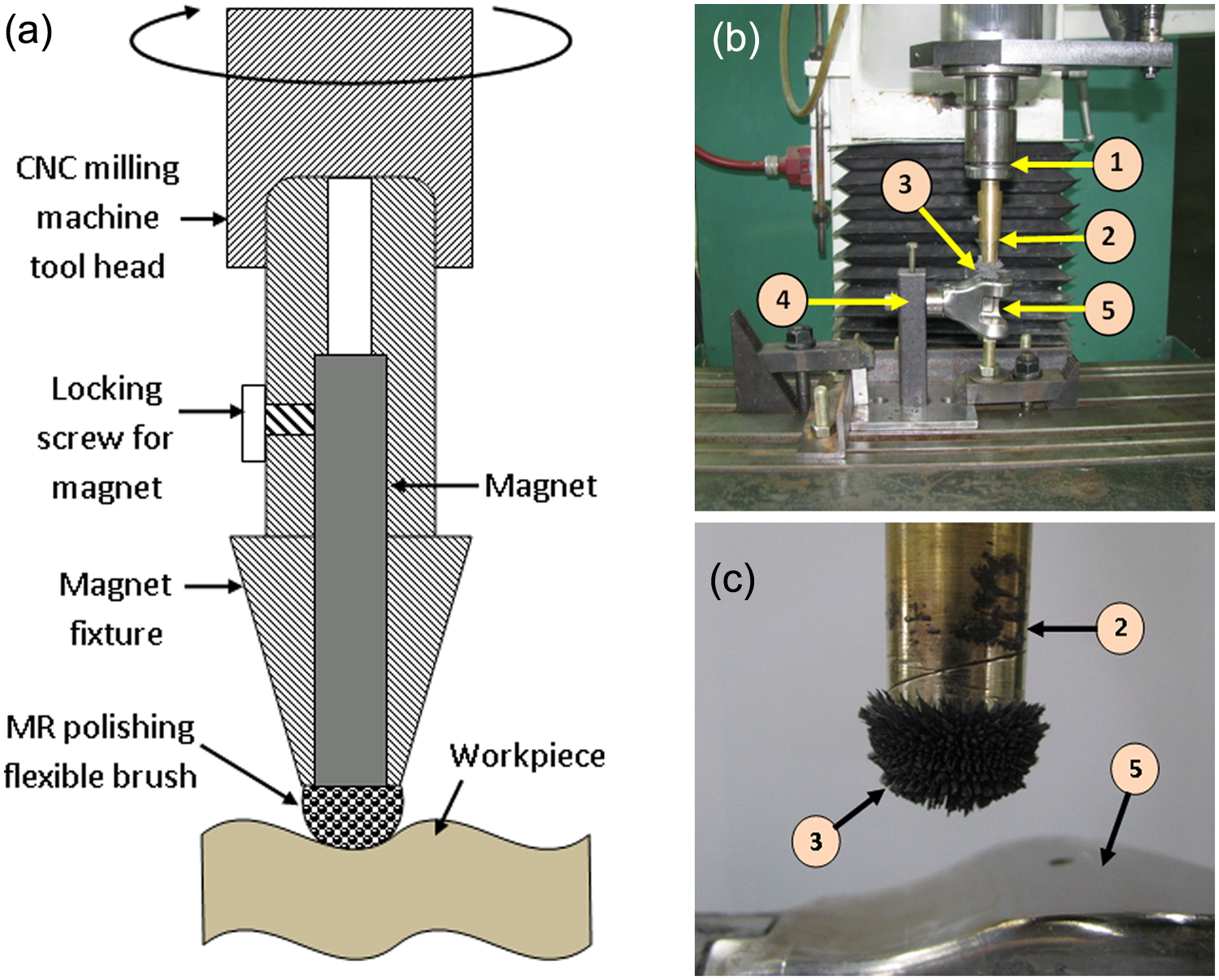
(a) Schematic diagram of the MRFF tool. (b) Photograph of MR finishing tool for freeform surfaces. (c) Close-up view of the MR polishing fluid (1: CNC milling machine head; 2: MR finishing tool; 3: MR polishing flexible brush; 4: fixture for knee joint implant; 5: knee joint implant).
MR polishing fluid
Performance of the MRFF process mostly relies on MR fluid, whose rheological behavior can be controlled by changing its constituents and magnetic field. Therefore, selection of proper MR fluid constituents plays a significant role on the quality of the final finished surface. There are three different kinds of MR fluids that have been used to finish the work material. All MR fluids are stirred for at least 1 hour before use, which results in uniform mixing of the solid particles in the base fluid.
Oil-based MR fluid has been used for finishing of stainless steel, brass, etc.17,18 Oil-based MR fluid is more stable against oxidation or corrosion owing to lubrication of solid particles (CIPs as well as abrasive particles). Hence, oil-based MR fluid is prepared that consists of CIPs, abrasive particles, and paraffin oil as a base material. Water-based MR fluid is commonly used for finishing silicon 19 and glass-based materials. 20 Water-based MR fluid consists of CIPs, abrasive particles, deionized water, and glycerol. Glycerol is used as a surfactant to impart stability to MR fluid. Water-based MR fluid exhibits high yield stress as compared with oil-based MR fluid when they are exposed to the same magnetic field.
When the surface roughness of any hard material is high, it is a little difficult and time consuming to remove material. Hence, in such cases, some chemical is required to soften the top surface of workpiece so that it can be easily removed by the abrasive particles of the MR fluid. The type of the chemical to be used depends on the material to be finished. In this case, the knee joint implant is made of titanium (160 VHN hardness), hence, chemicals that react with titanium, such as hydrofluoric acid (HF) and nitric acid (HNO3) are added to water-based MR fluid. HF etches (dissolves) while nitric acid prevents hydrogen embrittlement and it also brightens the surface of titanium. 21 Hydrogen embrittlement is the process by which various metals become brittle and fracture owing to exposure to hydrogen. It generally happens when hydrogen is introduced into the susceptible metals during the forming or finishing operation. The concentration of HF should be low and nitric acid should be comparatively high so that the surface does not get damaged. In the present case, 44 m CIPs and 1.6 m diamond powder are added in the solution having 3 g, 6 g, and 100 g of HF, HNO3, and H2O, respectively. 21 The following reactions take place when HF and HNO3 are used for titanium etching. 22
Titanium reacts with HF and produces water soluble complex (TiF6)3–

HNO3 reacts with H2 and it forms nitric oxide (NO) and water

The combined reaction of HF and HNO3 with titanium is given as
Experimentation
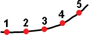
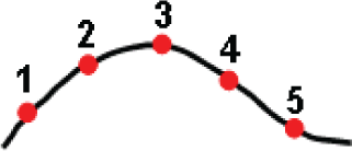
Experiments are conducted on a prosthetic knee joint implant (made of titanium) that has complex freeform surfaces. A set of experiments are carried out by different MR fluids as explained earlier. Surface roughness on the workpiece is measured by Surftest SV-2100M4 (Mitutoyo, Japan) at five different places on the same surface before and after finishing experiments. The measurements of the surface roughness on the curved surface (measurement points 3, 4 and 5, shown later in Figure 5) are carried out by aligning (by a rotating fixture) the surface parallel to the transverse direction of the probe. As per the ASME standard B46.1, when the variation of surface roughness is 0.1–2 µm, the cutoff length and evaluation length should be 0.8 mm and 4 mm, respectively. In the present case, the initial surface roughness varies from 147 nm (0.147 µm) to 524 nm (0.524 µm). Therefore, 0.8 mm and 4 mm are chosen as the cutoff length and evaluation length, respectively, for all the measurements.
A digital Gaussian filter is used for separating roughness from waviness and form error. Hence, the standard B46.1 suggests the high pass cutoff value is equal to sampling length when an electrical or digital filter is used. Therefore, the high pass cutoff value is 0.8 mm in the present case. Similarly, as per standard B46.1, the low pass cutoff should be selected depending on the stylus tip radius. In the present case, the stylus tip is diamond and it has a tip radius of 2 µm and tip angle of 60°. Hence, the corresponding low pass cutoff value is 2.5 µm, which is used for all measurements. Some scratches or other features may have dimensions of less than 2 µm or valley angles of less than 60°. In such cases, the stylus tip cannot trace the exact profile of these features owing to its dimensional limitation.
It is observed that the finishing efficiency of MR fluid decreases gradually with usage. 23 Hence, MR fluid is changed after every 30 min. It is difficult to finish titanium by relatively soft abrasive particles, such as cerium oxide, aluminum oxide, etc., hence, diamond powder (average particle size = 6 µm) is used in the present case, which has a high finishing rate compared with other abrasive particles. 20 The magnetic particles used in the present work to prepare MR fluids are CIPs of average particle size 6 µm (CD grade from BASF, Germany). A sintered Nd–Fe–B permanent magnet (N50 grade) is used for magnetization of MR fluid that has a maximum energy product (BHmax) of 48–51 MGOe. Figure 2 shows the variation of magnetic flux density (Tesla, T) in the working gap that is measured using a Gaussmeter. Magnetic flux density decreases as the working gap increases and it slightly varies from the center of the magnet towards the ends of the magnet. It is maximum at the edges and minimum at the center. In the present work, the working gap is kept constant as 1 mm for getting a higher finishing rate.
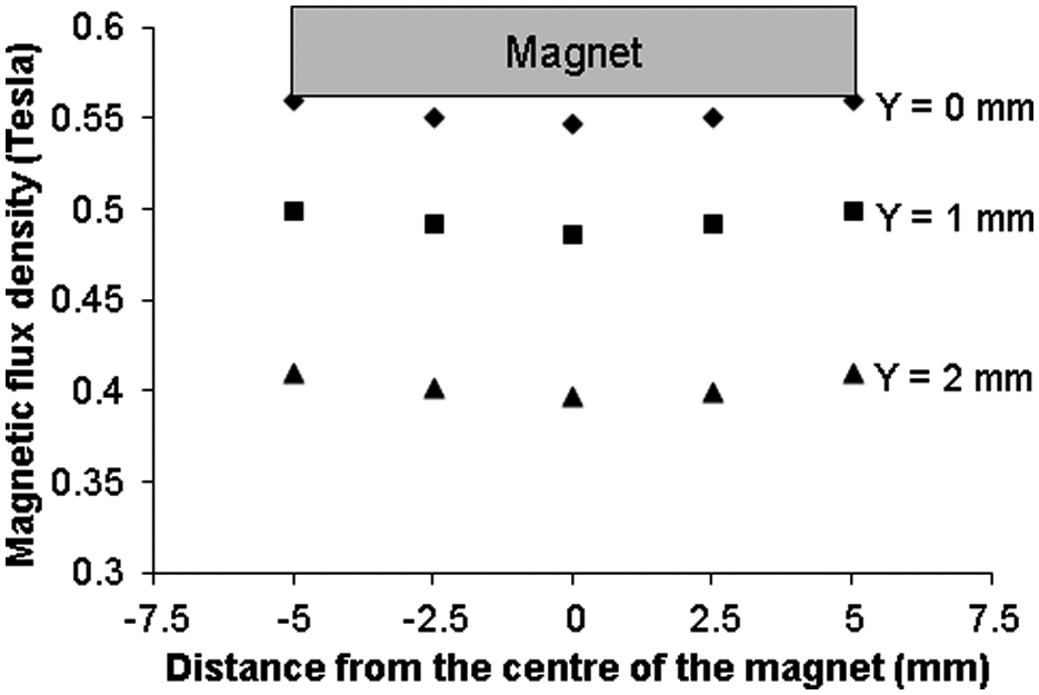
Variation in magnetic flux density in the working gap (y = working gap in mm).
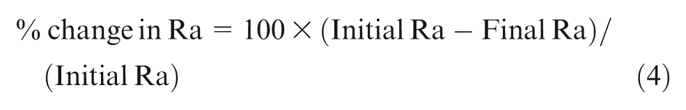
A set of experiments is carried out to study the effect of rotational speed of the MR finishing tool. Water-based MR fluid is used for these experiments. Other parameters, such as concentration of CIPs, concentration of abrasive particles, and working gap, are kept constant at 40%, 5%, and 1 mm, respectively. From Figure 3 it is found that, initially, final surface roughness (Ra) decreases with an increase in rotational speed of the MR finishing tool. However, beyond a particular rotational speed, surface roughness starts increasing. There is little variation in the initial surface roughness of the workpiece so percentage change in surface roughness is also calculated to normalize the effect of the initial surface roughness. The trend of percentage change in surface roughness is opposite to that of final surface roughness. The percentage change in surface roughness is calculated as
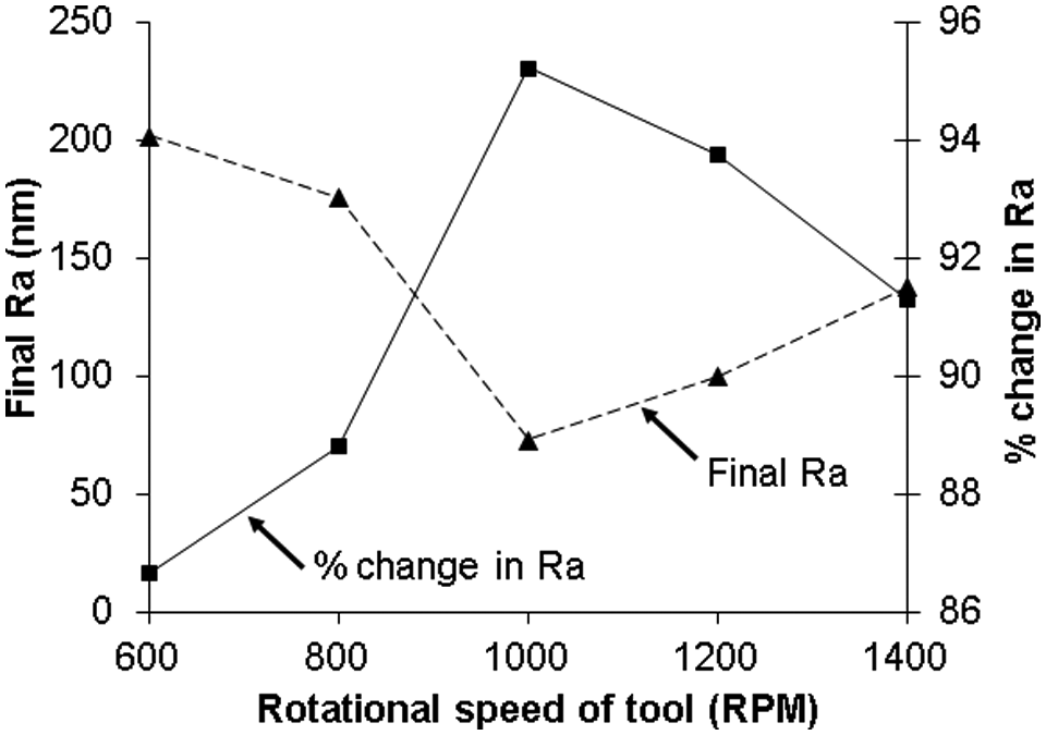
Effect of rotational speed of the tool on final surface roughness and percentage change in the surface roughness value.
One of the reasons may be that, initially, abrasive particles are not able to remove material efficiently owing to the low rotational speed, which is owing to the low abrading/cutting force. As rotational speed increases gradually, the cutting force of abrasive particles through MR fluid increases on the workpiece. However, further increase in the rotational speed results in destruction of CIPs chains structures, which is more prominent. Also, abrasive particles that are supported by these CIP chains get loosen. As a result, the cutting force of the abrasive particles acting on workpiece surface decreases and consequently percentage change in surface roughness also decreases.
Experiments are conducted on surface – 1 and surface – 2 (bottom surface) (Figure 4). To cover the whole area of the surface, the workpiece is moved in the X and Y directions. The raster tool path of the MR finishing tool is given and it is shown in Figure 4. The time required for one cycle or one step of finishing of surface – 1 and surface – 2 are 8.4 h and 8.2 h, respectively. Based on earlier reported work,23–25 some of the parameters are kept constant during the experiments (Table 1).
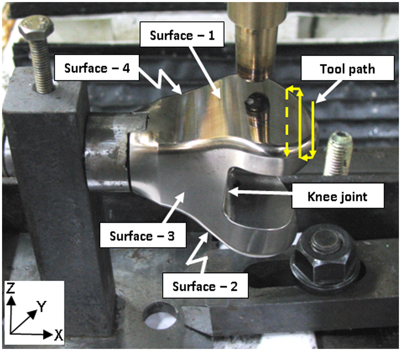
Location of surfaces – 1, 2, 3, and 4 on the semi-finished knee joint implant (surfaces – 2 and 4 are opposite to surfaces – 1 and 3).
Constant parameters during experiments.
MR: magnetorheological.
Owing to the unavailability of any standard procedure or guidelines for finishing of freeform surfaces such as a knee joint implant, a set of experiments is carried out on surface – 1 to study the effectiveness of different MR fluids in terms of the surface roughness value as follows. Initially, oil-based MR fluid is used to study its effectiveness in terms of surface roughness. It is observed that the initial surface roughness value decreases faster owing to high initial sharp peaks that are comparatively easily removed. Hence, a reasonably good average percentage change in surface roughness (39.76%) is obtained. However, no further improvement is observed with oil-based MR fluid. It seems that owing to the presence of oil, the interface between the MR fluid and workpiece becomes slippery (or low friction). Hence, in many cases, abrasive particles simply pass over the roughness peaks without shearing/cutting. Similar, results are also observed in the case of finishing of single crystal silicon. 19
After oil-based MR fluid, water-based MR fluid is used to further reduce surface roughness. It is found that final surface roughness decreases. In this step, the average percentage change in surface roughness is obtained as 36.41%. However, it is a little difficult to remove material from the workpiece that is already semi-finished by an oil-based MR fluid. Hence, it is attempted to soften the semi-finished surface with some chemicals so that it becomes easier to further reduce surface roughness. For this purpose, HF and nitric acid are added together in the water-based MR fluid. It is observed that the surface roughness value decreases (43.23% change in Ra), but the surface becomes dull owing to the chemical reaction between the MR fluid and workpiece. Hence, again water-based MR fluid is used to improve surface reflection, as well as to further lower the surface roughness value. In this step, percentage change in surface roughness is observed as 32.43%.
Figure 5 shows the surface roughness values obtained before and after finishing by the use of various MR fluids at different locations (shown as 1–5 in the window in the figure). The water-based MR fluid is used twice (before and after the chemical-based MR fluid) and their compositions in both cases are the same. It is observed that the lowest surface roughness value is achieved on point 2, while the highest surface roughness value is found at point 3.
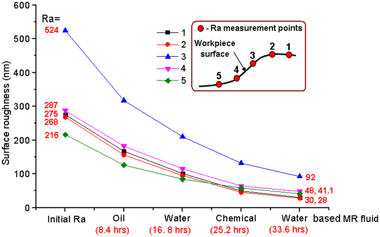
Effect of MR fluids on surface roughness on surface 1.
This large variation in final surface roughness is expected because there is a large variation in the initial surface roughness (216–524 nm). As a result, it is difficult to overcome this difference and get uniform surface roughness all over the surface. Furthermore, the finishing tool is held vertical in the CNC machine tool holder. Hence, the contact area of the MR fluid brush and the normal force (Fn, Figure 6(d)) are more on the surface, which is more or less flat (Figure 6(b)). As the curvature increases, the surface contact area of the MR fluid brush and the component of the force normal (Fr, Figure 6(d)) to this curved surface (responsible for penetration of abrasive particle in the workpiece surface) decrease (Figure 6(c)), which results in a lower cutting action of abrasive particles on the curved surface of the workpiece.
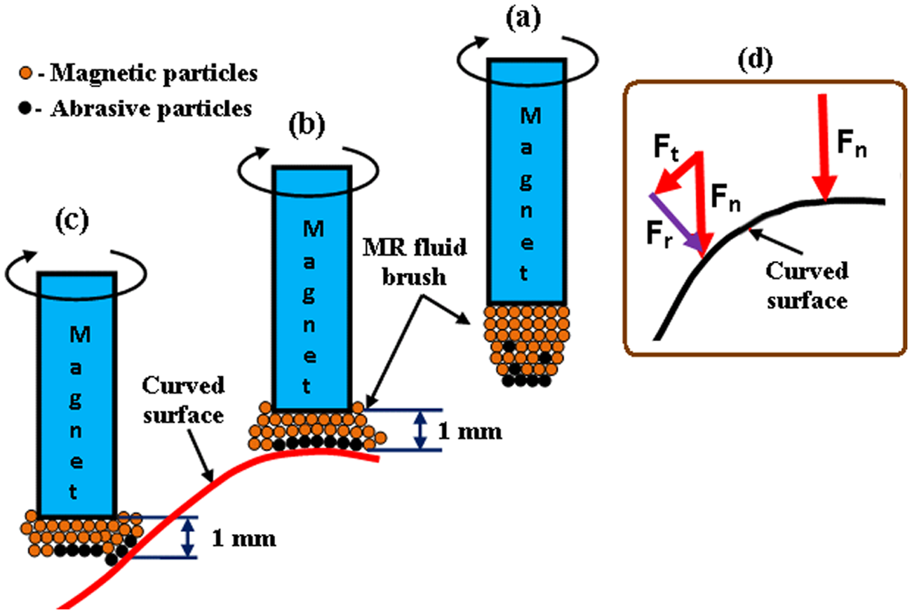
Schematic diagram of the condition of the MR fluid brush at different locations: (a) no contact; contact with (b) more or less flat surface, (c) curved surface, and (d) force diagram (Fn: normal force; Ft: tangential force; Fr: resultant force).
Furthermore, it is also observed that the working gap does not remain constant (1 mm) when the MRFF tool moves over the freeform surface. As a result, the stiffness (yield stress) of the MR fluid is also different at different working gaps. To validate the above inferences, a rheological study is also conducted to measure the yield stress of the MR fluids using a stress-controlled rheometer (Anton Paar MCR301 with MRD 180 attachment). The details of specification of the instrument are reported elsewhere.
26
The temperature is maintained at 25 °C during all the experiments by a thermal unit attached to the rheometer. Magnetic flux density is varied from 0.3 to 0.5 Tesla. For viscoplastic fluids, Bingham Plastic fluid model is generally used for measurement of yield stress and viscosity. Therefore, rheology curves of MR fluid are fitted with a Bingham Plastic fluid model for calculation of yield stress. The shear rate is varied from 0 to 3000 s−1 so that the maximum deformation of the MR fluid can be covered and studied. The shear stress (


where, η is the viscosity of the fluid.
Figure 7 shows that the yield stress and viscosity (resistance of MR fluid to flow) decrease with decreasing magnetic flux density (in other words, increase in the working gap). MR fluid, having a low yield stress, does not provide enough support to abrasive particles when they are in contact with the workpiece surface. Therefore, material removal does not occur efficiently. When the yield stress of MR fluid is high, abrasive particles effectively engage with the workpiece surface and higher improvement in surface finish is observed.
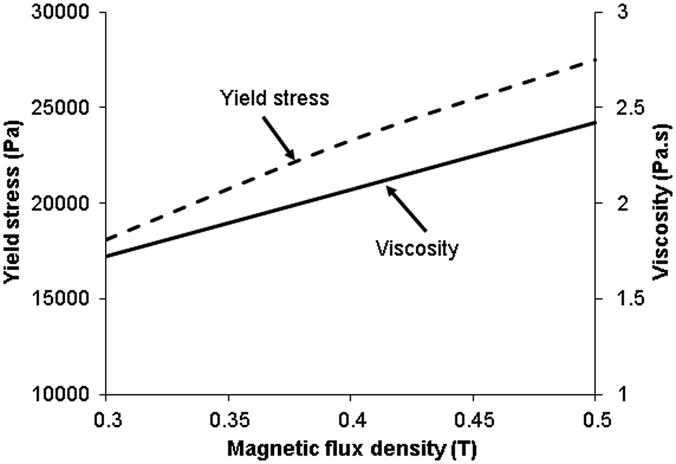
Variation in yield stress and viscosity with magnetic flux density (CIPs = 40%, abrasive particles = 5%, water = 47%, and glycerol = 8%).
Surface roughness (2D, Figure 8) and surface topography (3D, Figure 9) are measured by a surface roughness tester and atomic force microscope, respectively, to study the profile and texture on the finished surface of the workpiece. It is observed that initial peaks on the surface of the workpiece get flattened in the successive finishing by different types of MR fluids.
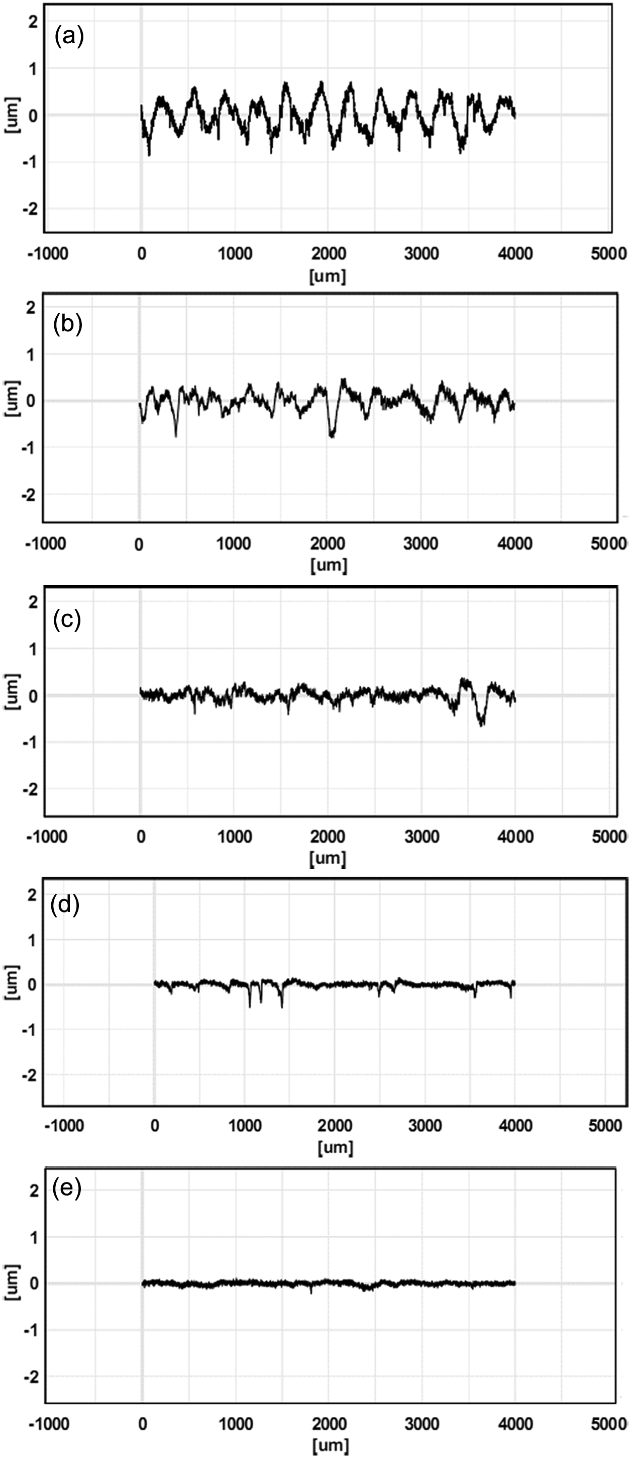
Surface roughness plots of measurement at point – 2. (a) Initial surface roughness = 268 nm; final surface roughness with (b) oil-based MR fluid = 156 nm, (c) water-based MR fluid = 95 nm, (d) chemical-based MR fluid = 45.4 nm, and (e) water-based MR fluid = 28 nm.
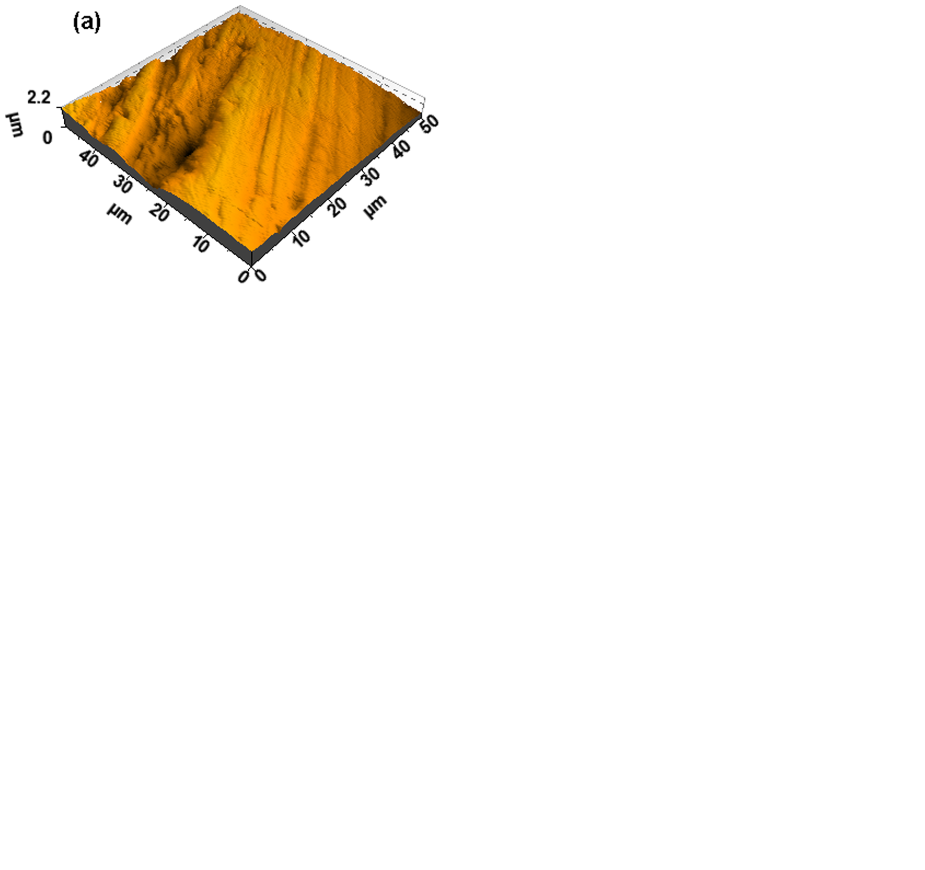
Atomic force microscope images of measurement at point – 2. (a) Initial area roughness = 223 nm, final area roughness after finishing with (b) oil-based MR fluid = 140-nm, (c) water-based MR fluid = 88.5-nm, (d) chemical-based MR fluid = 37.4-nm, and (e) water-based MR fluid = 21.7-nm.
Based on the observations of the results on surface – 1, it is deduced that some intermediate finishing steps by different types of MR fluids can be omitted to reduce finishing time. Therefore, finishing with oil-based (1st step) and water-based (2nd step) MR fluids are excluded and only chemical (3rd step) and water-based (4th step) MR fluids are used for the finishing of surface – 2. The surface roughness results are shown in Figure 10, and it is found that the results are close to those obtained in the case of surface – 1. Surface roughness plots (Figure 11) of finished surface – 2 are similar to that of surface – 1 (Figure 8). The proposed new steps have reduced the finishing time significantly. The total finishing time for surface – 1 was 33.6 h (four steps finishing by four different MR fluids), while surface – 2 was finished in 16.4 h (two steps finishing by two different MR fluids). The variation in surface roughness from its average value at different locations on the same surface is shown in Figure 12(a) and 12(b) for surface – 1 and surface – 2, respectively. It is found that the variation in surface roughness values reduces in the subsequent finishing steps. Hence, the stepwise finishing reduces the large variation in roughness on the same surface. The standard error also reduces from 53.88 nm to 11.63 nm and 13.81 nm to 12.14 nm in the case of surface – 1 and surface – 2, respectively (nm stands for nanometer).
Effect of MR fluids on surface roughness on surface – 2.

Surface roughness plots of measurement at point – 2. (a) Initial surface roughness = 210 nm, final surface roughness with (b) chemical-based MR fluid = 50 nm, and (e) water-based MR fluid = 29 nm.
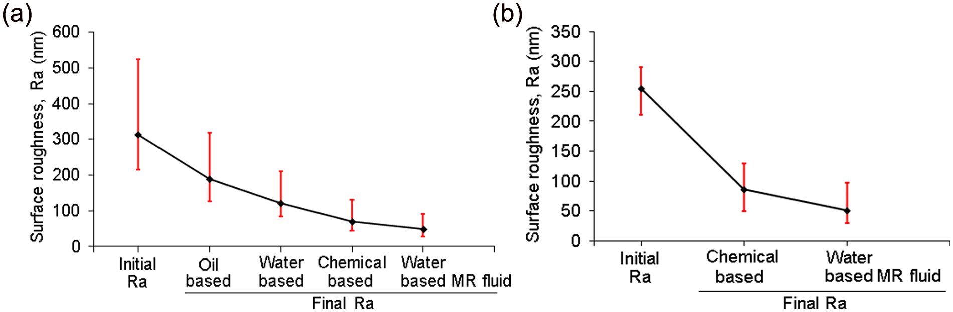
Variation in the surface roughness values on (a) surface – 1 and (b) surface – 2.
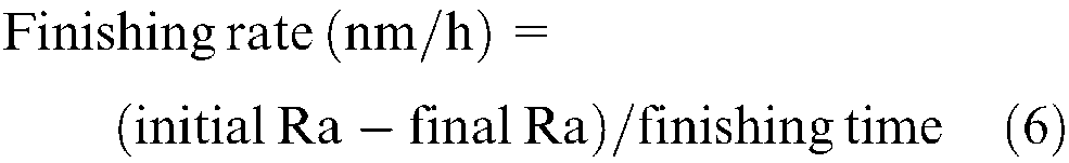
The finishing rate is also measured on both the surfaces as shown in Figure 13. Finishing rate is calculated in nm/h by measuring initial surface roughness, final surface roughness, and the finishing time, which is given by
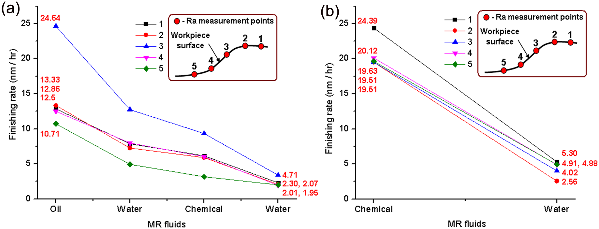
Variation of finishing rate results of (a) surface – 1 and (b) surface – 2.
It is observed that the finishing rate is high in the beginning and then it starts decreasing in the consecutive finishing cycles (Figure 13). Initially the surface roughness peaks are high (Figure 8(a)) and the top area of those peaks is also small. Hence, it is easy to remove these peaks, which results in a high finishing rate. As finishing progresses, top area of peaks increases (Figure 8(b)–(e)) which makes it difficult for abrasive particles to remove them with the same finishing rate. Hence, finishing rate decreases with a reduction in surface roughness.
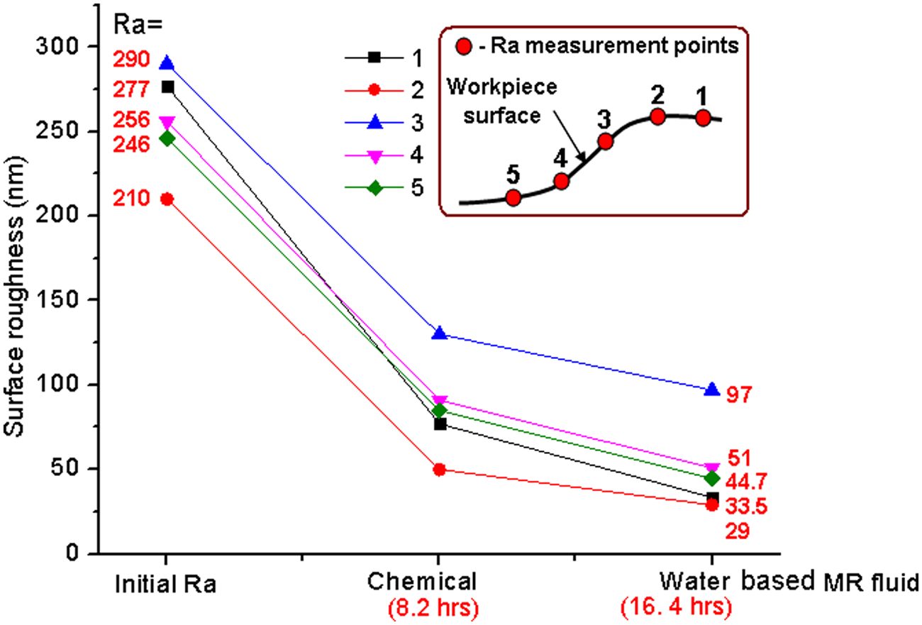
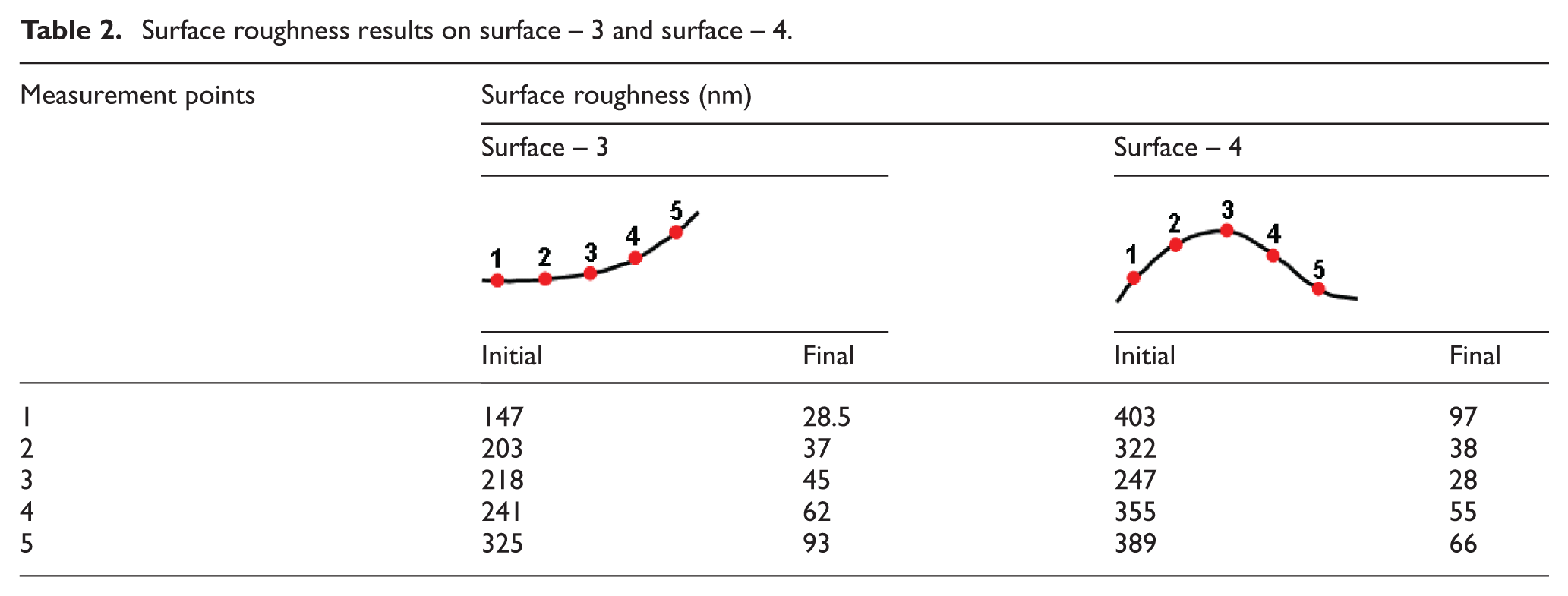
Based on the observations of results of surface – 1 and surface – 2, other surfaces – 3 and 4 (Figure 4) are also finished in 2 steps, similar to surface – 2. The results of surface roughness measurements are given in Table 2. It is evident that the results of the final surface roughness are almost similar to those obtained for surfaces – 1 and 2. The results of all four surfaces also reflect the consistency of the MRFF process. It is also important to mention here that, as per the ASTM standard, the surface roughness value (Ra) on the metallic knee joint implant should not be more than 100 nm. 27 In the present case, the worst surface roughness is 97 nm, which is within the acceptable limit.
Surface roughness results on surface – 3 and surface – 4.
After finishing with the chemical-based MR fluid, in some cases, scratches on the finished surface are observed in an Atomic force microscope (AFM) image as shown in Figure 14(a). The top surface of the workpiece gets softened owing to the chemical reaction and it leads to scratches owing to rubbing of abrasive particles over it (the two arrows indicate the direction of the two abrasive particles’ movement resulting in two scratches). These scratches are removed in the subsequent finishing step by water-based MR fluid. However, there is some scoring observed on the final finished surface as shown in Figure 14(b). This sometime happens when an abrasive particle penetrates the surface but it is not able to remove the material ahead of it owing to the axial force smaller than the resistance offered by the workpiece material for finishing. As a result, it just rotates without further removal of material. These phenomena are explained in detail elsewhere. 23
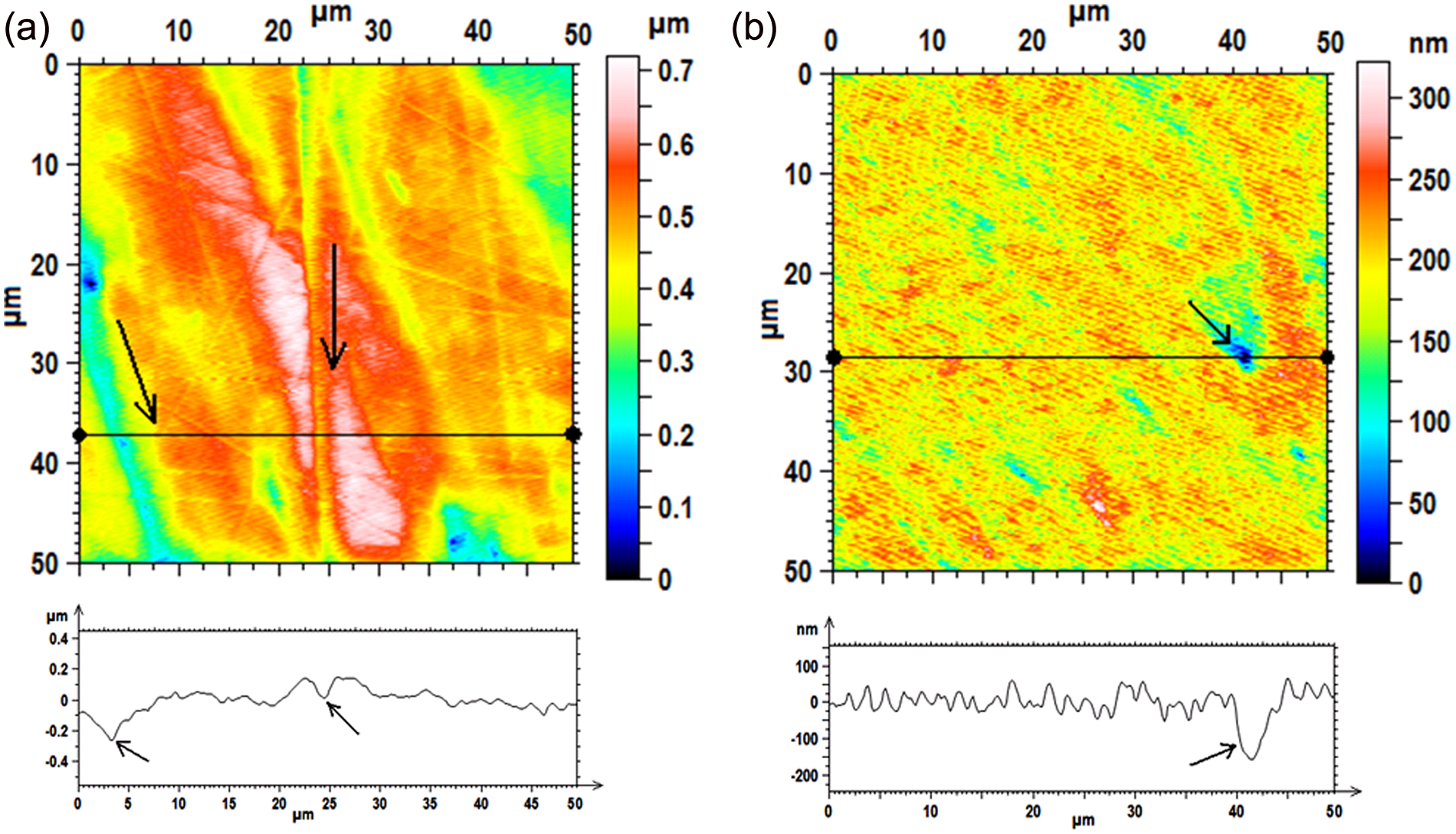
AFM images and surface cross-sectional profiles (at horizontal cross bars) of surface – 2 (a) after finishing with chemicals based MR fluid and (b) after finishing with water-based MR fluid.
Figure 15 shows the photographs of the initial and finished surface of the knee joint implant. It is seen that the reflection of “IITK-BARC” letters is quite clear on the workpiece surface after final finishing (Figure 15(c)) as compared with the initial surface (Figure 15(a)). These results show that the process is capable of finishing freeform surfaces to the desired level of surface roughness value.
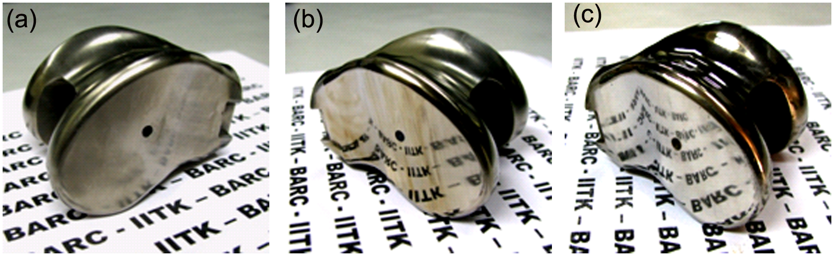
Photograph of (a) initial surface, finished with (b) chemical based MR fluid and (c) water-based MR fluid (complete finished part).
Effect of surface curvature on the finishing time
It is observed that, in the present study, the finishing time required is a little high because of the freeform surface of the workpiece and varying finishing rate in different location of a surface. To further reduce the finishing time and to have a more uniform surface finish in different locations of a face (or surfaces 1 – 4), use of a five-axes controller for the CNC milling machine or independent machine is recommended. In the present case, to finish a whole surface, the workpiece is moved in X and Y direction (Figure 4) at 1 mm working gap and a small offset of 1 mm in X direction is given after every movement of Y direction travel. The reason for giving such a small X direction offset, despite the 10 mm MRFF tool diameter, is that the three-axes CNC machine has a fixed Z-axis that can only move up and down in a vertical direction and rotates around its own axis. When the tool passes over the flat surface, the whole bottom surface of the tool maintains a 1 mm working gap with the workpiece and finishes the area as covered by the MR fluid flexible brush or tool. However, for finishing of a curved surface, only a small portion of the tool maintains 1 mm working gap, while the rest of the tool’s bottom portion is away from the workpiece surface (as shown in Figure 16). As a result, the curved surface finishing takes place on a small portion of the workpiece. In such a case, an offset in the X direction more than 1 mm would result in an unfinished area between two finishing paths.
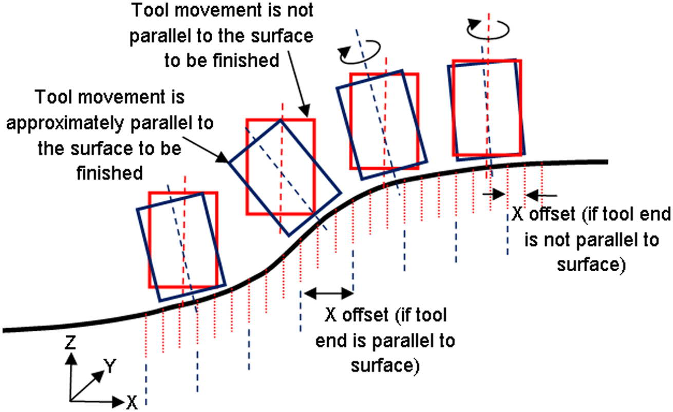
Illustration of the movement of the MRFF tool along the workpiece surface.
If the arrangement is made in such a way that, along with the rotation of the Z-axis, it can also tilt (as shown in Figure 16), the larger part of the bottom area of the tool maintains approximately 1 mm working gap. In this case, uniformity of surface roughness and a higher finishing rate would be possible to achieve. When a constant working gap is maintained, a uniform magnetic field (Figure 2) is available on the workpiece surface. As a result, consistent and effective finishing would take place with a stiffened MR fluid. This arrangement will not only reduce finishing time but also reduces surface roughness significantly. Therefore, a five- or more axes controlled machine is required when the curvature of the surface is more, and more precise components are required to be finished.
Conclusions
An experimental investigation is carried out to observe the effect of different MR fluids on the surface roughness and finishing rate for finishing a knee joint implant by the MRFF process. Based on the results and discussions, the following conclusions are drawn.
The MRFF process is recommended for finishing freeform complex surfaces to nanometer surface roughness value.
The addition of appropriate chemicals (HF and HNO3) in MR fluid significantly enhances the finishing rate of titanium despite of its high initial surface roughness. The finishing time and surface roughness can be reduced further using a five-axes CNC machine.
The final finishing with water-based MR fluid improves surface finish and surface brightness by removal of a chemically reacted surface layer by the abrasive particles.
The finishing with a chemical-based MR fluid, followed by a water-based MR fluid, is more effective.
The best surface roughness value achieved is 28 nm, with the variation in the range of 28–93 nm depending upon the local curvature of the surface.
Footnotes
Acknowledgements
We thankfully acknowledgment the Bhabha Atomic Research Centre, Bombay [project no. BARC/Works/MoU/321/2011/] and the Council of Scientific and Industrial Research (CSIR) New Delhi, India [project no. 22(0479)/09/EMR-II] for their financial support. We sincerely thank BASF, Germany for arranging carbonyl iron powders of different grades for our research work.
Funding
This research received funding from the Bhabha atomic research center, Bombay [project no. BARC/ME/20100374] and the Council of Scientific and Industrial Research (CSIR), New Delhi, India [project no. 22(0479)/09/EMR-II].