
Abstract
The article aims to show that the electrical discharge machining plasma can be developed in solid or gaseous medium, through the numerical and experimental evaluation of process performance. The plasma channel developed in gaseous medium is based on an electrical discharge developed in a gas bubble and the plasma channel developed in solid medium is based on underwater explosions. The main electrical difference between both mediums is on its electrical resistivity. However, if the radius of plasma channel increases, its electrical resistivity should decrease because its electrical resistance and applied current intensity are constant, or in other words, the applied electrical power is constant during discharge duration. Thus, the plasma channel is developed in gaseous and solid mediums, with same electrical resistivity and Joule factor, because the radius of plasma channel is considered constant during discharge duration. The comparison of numerical results of electrical discharge machining performance obtained through an electrical discharge machining plasma developed in gaseous and solid mediums shows high agreement with the experimental results. Therefore, the electrical discharge machining plasma developed in solid and gaseous mediums is reliable when hydrocarbon oil is used as a dielectric fluid due to the high degree of agreement of numerical and experimental results of electrical discharge machining performance.
Introduction
Electrical discharge machining (EDM) is a non-conventional machining process, where the electrodes are submerged into a dielectric fluid and separated by several tens of microns. The tool electrode moves in direction to workpiece and when the distance between them is small enough to cause breakdown of the insulating properties of the dielectric, the voltage falls to 22.5 V and the current rises to a constant value set by the operator.
The electrical discharge developed in a bubble of gas creates an ionized gas channel (plasma channel) that increases its radius during discharge duration, leading to a decrease in the current density that causes a recession in the temperature of both electrodes. Moreover, in underwater explosions, a metal wire is used for the development of the plasma channel, which increases its radius, leading to a decrease in the current density. The assumption that the EDM plasma is developed in a solid medium is pointed out in Kunieda et al. 1 and Schumacher, 2 where authors state that the particles of graphite form a chain that acts as ignition to the electrical discharge. The electrical discharge can be developed in particles of electrode material, besides the particles of graphite formed with the high pressure and temperature during the dielectric breakdown. 3 Therefore, the plasma channel developed in a gas bubble with two distinct values of thermal conductivity and developed in a graphite particles chain was considered, based on maintenance of its electrical resistivity and Joule factor.
The studies on material removal in EDM are generally done with models distinct for anode and cathode, and therefore, they did not consider this subject. The characteristics of the anode 4 and cathode 5 models are as follows:
Anode model is based on an expanding circular power source, which means that the radius of plasma channel increases with time. Therefore, this heat source allows a decrease in the current density that creates a recede in the temperature of anode.
Discharge crater of the cathode has a semi-spherical shape, because was used the point heat source that is equivalent to the cylindrical heat source. The cylindrical discharge machining plasma (heat source) used had a constant radius during the simulation of electrical discharge, which is the three-dimensional heat source equivalent to the point heat source used in the bi-dimensional analysis. Therefore, the radius of heat source is constant and consequently the current density and electrical resistivity, not allowing for the recession of temperature in the cathode. The applied electrical power is constant, and as current density and electrical resistivity are constant, the Joule factor is also constant. Thus, if the radii of the plasma channel increase, replacing another value of current density, then there is a decrease in the electrical resistivity because the electrical resistance (R) is constant, not allowing for the recession of the temperature in the plasma channel. Moreover, the temperature in the plasma does not recede during discharge duration according to DiBitonto et al. 5 The effect of electrical resistance, electrical resistivity and current density is demonstrated through the equations (1)–(3)
and
The analysis of both models allows to conclude that the anode model uses an expanding circular heat source in order to reduce the volume of melted material through the recession in the temperature of anode or decrease in the temperature of plasma channel. On the one hand, the research by Albiński et al. 6 shows that the temperature in the EDM plasma is around 12,000 K, which means that it is the maximum temperature of the plasma. On the other hand, the research by Ojima and Kunieda 7 shows that the temperature in the EDM plasma is around 6000 K, reducing remarkably the plasma volume, because the ionization temperature of the dielectric is around 6000 K, according to research by Arunachalam et al. 3 The small radius of plasma channel is shown in the research by Schumacher 2 who points out that the debris particles form a chain between bubbles, acting as ignition to the electrical discharge. The radius of plasma channel is limited to initial radius of the dielectric breakdown as pointed out in the research by Singh and Ghosh. 8 Therefore, a heat source with constant radius in the modeling was used, due to limited volume ionized, and thus, the center position of heat source is the main cause of recession and increase of the electrodes’ temperature, as shown in the research by Fonseca and Marafona. 9
The authors agree that an increase in the radius of plasma channel leads to a decrease in the current density, not considering the increase in the electrical resistivity (Ω) of the plasma channel.
The increase in the radius of plasma channel leads to a decrease in the current density, being the electrical resistance constant occurs an increase in the electrical resistivity of the plasma channel, maintaining the energy dissipated. However, the loss of mass of electrodes owing to sublimation causes an increase in gap width, leading to a decrease in working voltage, the equilibrium being reestablished with a movement of the heat source center. Therefore, the center of heat source stays closer to the electrode with greater erosion and further away from the electrode with less erosion. The new position of the center of the heat source creates decrease and increase in temperature in the tool and workpiece at each moment.
Heavy hydrocarbon oil was used in the experiments. The ignition of electrical discharge was simulated in a bubble of gas. The plasma channel developed in a gaseous medium was simulated twice with different values of thermal conductivity, which are the thermal conductivity of an ionized gas (60 W/m K) and of the graphite (160 W/m K). The ignition of electrical discharge was also simulated in a solid medium with the thermal and physical properties of the graphite.
The amount of electrical energy converted into thermal energy by Joule heating is 35% because the electrical resistance of the plasma channel is constant and is used to remove material of the electrodes during the discharge. The multiple discharges affect the material removed from the electrodes and they were used in the simulation. The numerical model of the research by Fonseca and Marafona 9 was used to obtain the results through two runs. The material removal rate and the workpiece surface roughness are obtained in the first run and the tool wear rate is obtained in the other run.
The main reason for this study is the development of plasma channel in gaseous and solid mediums, including the thermal and electrical conductivity, as shown here. The electrical discharge developed in solid medium is referred in the research by Fonseca and Marafona 9 and is related to a graphite particles chain or particles of electrode material, which act as ignition to the electrical discharge, as shown in the research by Schumacher. 2 High pressure and a temperature around 1500 K are conditions for the formation of graphite 3 that sublimates due to change in the temperature and pressure in the plasma channel during electrical discharge. Thus, the solid particles used as ignition to the electrical discharge have the properties of graphite, which is formed during the breakdown of hydrocarbon oil.
The plasma channel developed in the gaseous medium was considered in the research by Marafona and Chousal, 10 simulating an electrical discharge in deionized water. The plasma channel developed in gaseous medium in deionized water should have thermal and electrical conductivity of a gas, which is formed during the breakdown of the deionized water. This study demonstrates that the radius of plasma channel is associated with a restricted ionized volume and that plasma channel can be developed in a solid or gaseous medium, whose numerical results of performance agree well and also with experimental data.
Numerical modeling
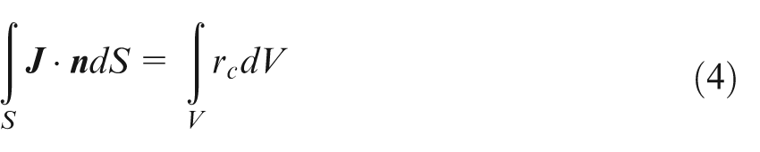
The numerical analysis is electro-thermal through the transformation of electrical energy into heat by Joule heating effect. The main equation of the study is the Maxwell equation of charge conservation. Maxwell’s equation of charge conservation governs the electric field in a conducting material. In order to simplify the equation, steady-state direct current is considered. So, the equation reduces to
The electrical conductivity of plasma channel is considered independent of its temperature because it is coherent with the small decrease in temperature during discharge current, according to researches by Albiński et al. 6 and Ojima and Kunieda. 7 The electrical conductivity in both electrodes is considered independent of its temperature. The thermal conductivity of the electrodes is considered dependent on its temperature because it is associated with the metallurgical transformation of the metals, which are at high temperature and undergo fast cooling during the electrical discharge. However, the thermal conductivity of plasma channel is independent of its temperature, because the temperature of the plasma is considered constant during electrical discharge.
Initially, all parts of the model are at the temperature of the dielectric, 287 K, which is maintained constant by a cooler during EDM. The heat generated is only owing to the electrical current that passes through the plasma channel, where Joule heating transforms electrical current into heat, which is transferred to the electrodes through conduction. The plasma channel loses heat to the dielectric fluid by radiation and convection; however, only the first is taken into account in the numerical model.
The Joule heating factor is 35%, because the Joule factor and electrical conductivity are equal in both mediums of electrical discharge ignition, which is used to remove material during electrical discharge.1,9 The energy lost to the dielectric is around 18% 1 and can reach 35% due to the electrodes’ material evaporation as shown during research. So, the electrodes’ material is removed by evaporation during electrical discharge, the melted material being removed at the final electrical discharge due to electrical potential gradient or/and using flushing of the gap.
Methodology
Properties of ignition medium, tool and workpiece
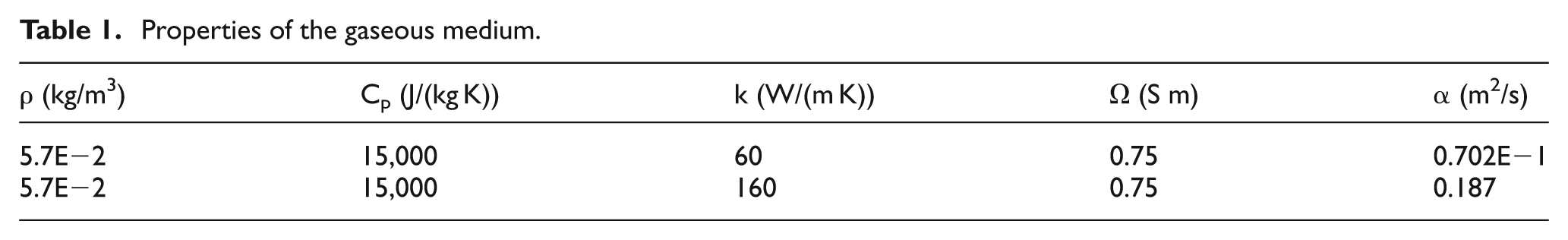
Two sets of properties were selected to evaluate the effect on the EDM performance of the plasma developed in gaseous medium. One of the sets is related to the fact that the plasma be developed in gaseous medium, with low thermal conductivity such that the electrical discharge ignition occurs in gaseous medium, one of the many bubbles in the gap.1,2 A different value of thermal conductivity was assigned to the gas bubble because the vaporization of hydrocarbon oil releases carbon compounds. 2 These properties and the properties already used in the research by Marafona and Chousal 10 are shown in Table 1.
Properties of the gaseous medium.
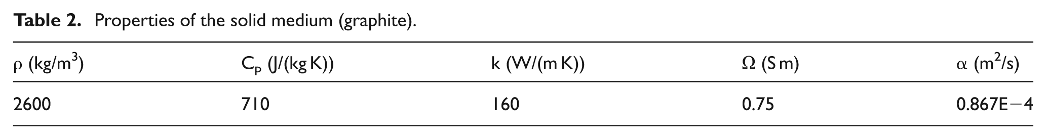
Another set of properties is related to the assumption that the ignition of electrical discharge occurs in solid medium, whose properties were already used in the work by Fonseca and Marafona 9 and are shown in Table 2.
Properties of the solid medium (graphite).
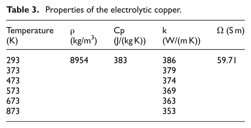
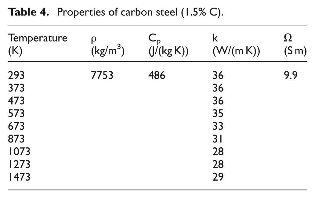
In the numerical simulation, the material of tool was the electrolytic copper, whose properties are shown in Table 3. The material of workpiece was the carbon steel (1.5% C) and its properties are shown in Table 4. The shapes of tool and workpiece are cylindrical and their radius and height are approximately 50 times greater than the gap width.
Properties of the electrolytic copper.
Properties of carbon steel (1.5% C).
The experiments were carried out in an AGIE COMPACT 3 machine in the DEMec Laboratory, using hydrocarbon oil and without flushing of the gap. The experiments were carried out with electrolytic copper rod, with 16 mm diameter and 100 mm length and with carbon steel, AISI D2, with dimensions 250 × 75 × 25 mm.
Dimensions of plasma channel
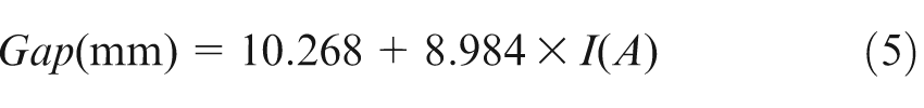
The gap width was calculated using equation (5), according to the research by Eubank et al. 11
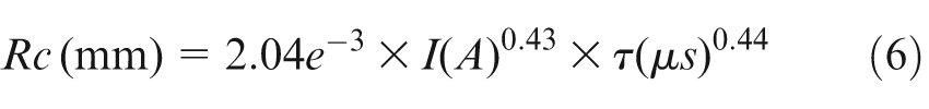
The radius of plasma channel (Rc) is calculated through equation (6) for the time of 0.75 µs, according to the research by Ikai. 12 The radius of plasma channel is maintained constant throughout the simulation; in other words, the plasma channel is ionized in a very restricted volume because the standard voltage control (3 V) does not allow its expansion
The Joule heating factor is influenced by the electrical conductivity of the plasma channel as mentioned in the research by Marafona and Chousal. 10 Hence, equation (3) is used to calculate the electrical conductivity of the plasma using the discharge voltage.
Surface roughness and calculation of the number of discharges
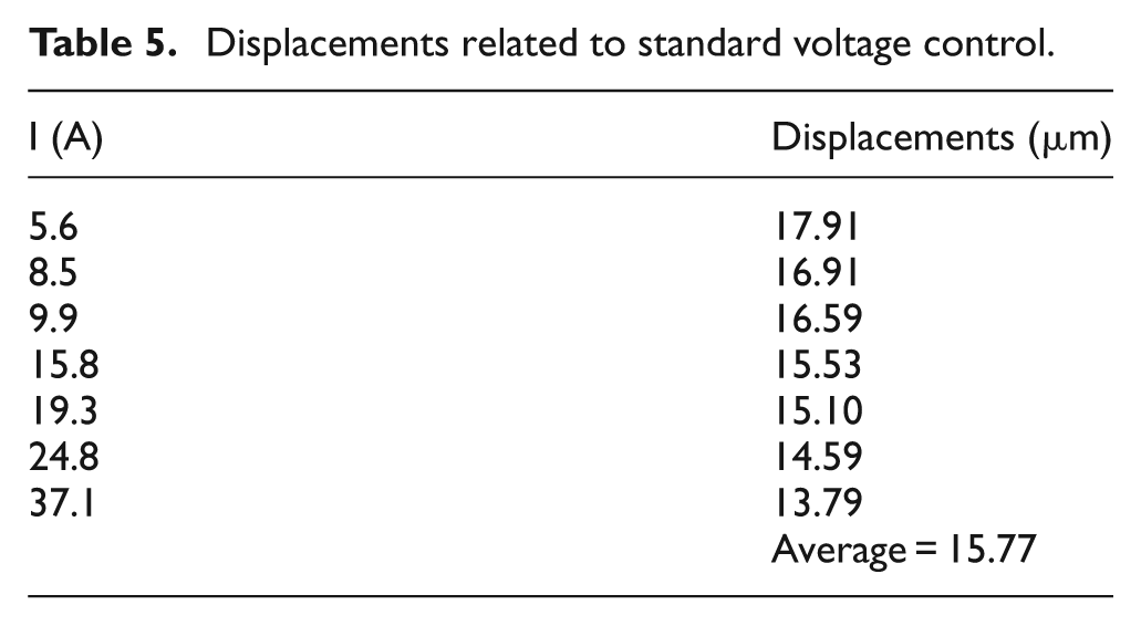
The increase in the discharge crater depth, called displacement, is related to servo reference voltage control (3 V) and it was calculated based on the linear relation between the discharge voltage and the gap width. The average of displacements is 15.77 µm and thus the standard voltage control (3 V) was taken equal to 16 µm in the study. An example of calculation of the relation is shown below for 9.9 A current intensity, and the other results are shown in Table 5.
From equation 3, electrical potential = 17.95 V, discharge gap = 99.21 µm.
Using servo voltage, electrical potential = 3 V, discharge width = 16.59 µm.
Displacements related to standard voltage control.
Thus, the number of discharges that occurs in a current single pulse is calculated based on the depth of workpiece crater divided by 16 µm. The depth of the workpiece crater is obtained under the effect of 35% of the electrical energy converted to thermal energy, giving origin to a single cavity. However, the servomechanism does not have capacity to maintain a single discharge if a 3 V variation is detected, corresponding to an erosion depth equal to 16 µm because the voltage control is maintained at 22.5 V ± 3 V. Thus, there occurs another discharge in a peak of the surface roughness pattern or an incomplete discharge if the 35% energy is not used (−3 V). Therefore, the number of discharges is multiplicative to the material removal rate and is reductive to the tool wear rate, because the heat source will be closer to the workpiece and will be further away from the tool.
EDM input parameters
The experimental data were obtained with the input parameters shown in Table 6. The numerical results were obtained with 200 V open voltage and with 35% of energy of the discharge current applied to the gap width.
Input parameters used in the experiments.
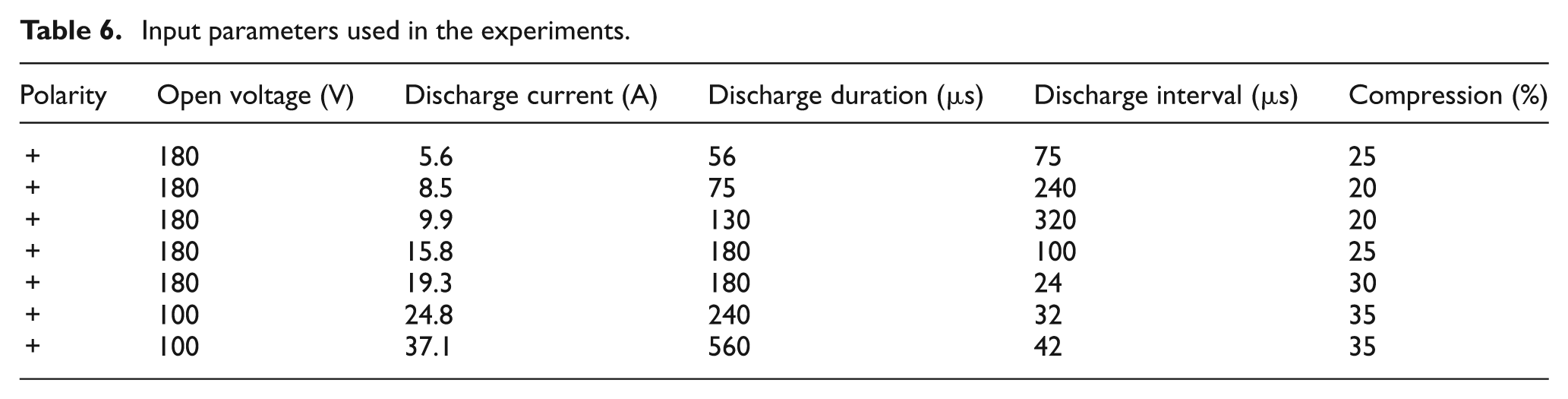
The parameter “compression” is the degree of deterioration of the gap, according to the machine manufacturer.
Results and discussion
The analysis of the performance parameters of EDM begins with workpiece surface roughness. Numerical analysis shows that the roughness workpiece surface has similar behavior for the plasma channel developed in solid and gaseous mediums; however, the numerical results for the plasma channel in solid medium have a high agreement with the experimental data. The plasma channel built in gaseous medium with high thermal conductivity shows a high agreement with the numerical results obtained with plasma channel developed in solid medium. On the other hand, the plasma channel developed in gaseous medium with low thermal conductivity shows a low agreement with experimental data, as can be seen in Figure 1. In fact, the numerical results are below of experimental data, with exception for 37.1 A of current intensity, indicating that the numerical result of workpiece surface roughness was obtained with 200 V open voltage and not with the 100 V open voltage used experimentally. The numerical results of workpiece surface roughness are below of the experimental data because numerical value of surface roughness is the average maximum roughness and not the maximum roughness of workpiece surface. The last statement is based on replication of the tool surface roughness on workpiece surface. Therefore, one must take into account the arithmetical average roughness of tool surface, when calculating the maximum roughness of workpiece surface. So, one can conclude that the numerical results of the roughness of workpiece surface are in agreement with the experimental data when the plasma channel is developed in solid and gaseous mediums. The roughness of surface is related to material removal rate and more specifically with the occurrence of multiple discharges and so the explanation for the phenomenon of large instability in the beginning of machining as pointed out in research by Yoshida et al., 13 which can be attributed to very small surface roughness of workpiece. Thus, incomplete discharges occur because the workpiece surface roughness pattern does not allow the use of all energy available (35%) to remove material and therefore, only the energy associated with the standard voltage control (3 V) is used.
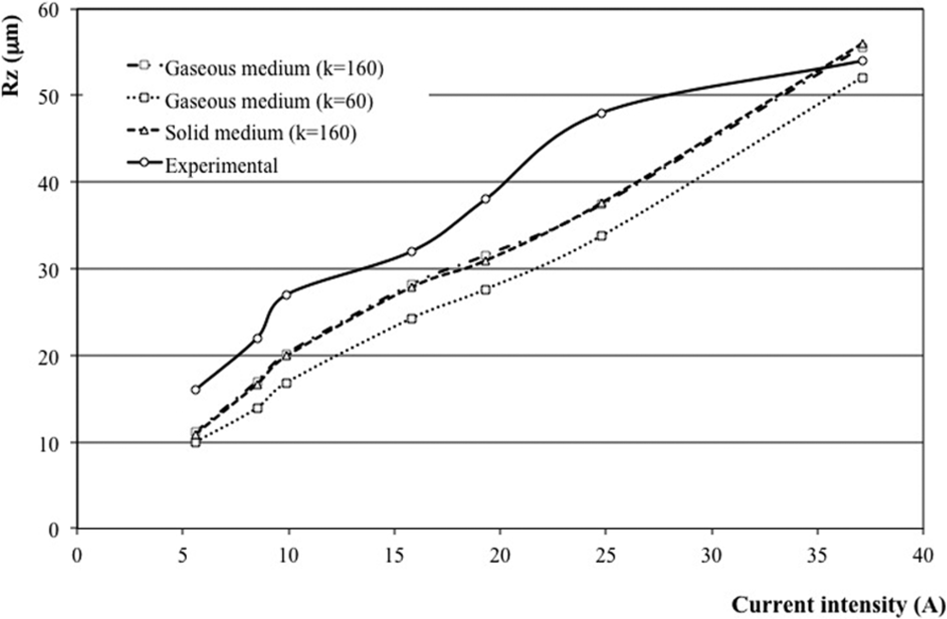
Comparison of numerical results with the experimental data of workpiece surface roughness.
The numerical results of tool wear ratio have a good degree of agreement with the experimental data. However, its behavior is not so coherent as the numerical results of workpiece surface roughness with experimental data. The experimental data of tool wear ratio does not agree with numerical results using the plasma channel developed in gaseous medium, with low thermal conductivity. Moreover, the numerical result of tool wear ratio is approximately zero for 5.6 A current intensity and, thus, does not appear in Figure 2. On the one hand, the numerical results of tool wear ratio are higher than experimental data for current intensities greater or equal to 15 A. On the other hand, the numerical results of tool wear ratio are lower than experimental data for current intensities lower than 15 A, as can be seen in Figure 2. The discrepancy between numerical results and experimental data is explained by the existence of an electrical potential gradient capable to remove more than the melted material in the case of electrical discharge of small duration. The same electrical potential gradient does not remove all melted material, because there is a higher amount of melted material that should be removed in the case of the electrical discharge of long duration. So, the numerical results of tool wear ratio are higher than the experimental data for high current intensities, because the pressure exerted on melted material is not enough to remove it when plasma channel collapses.
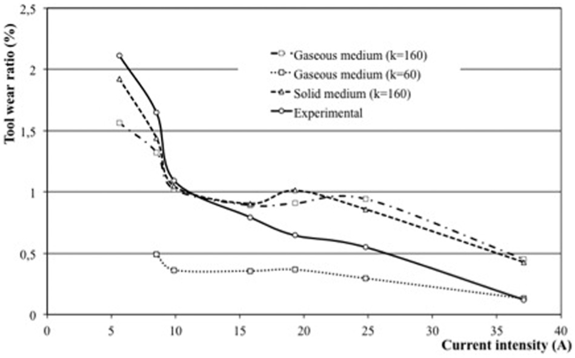
Comparison of numerical and experimental tool wear ratio.
Once again, the numerical results using plasma channel developed in solid and gaseous mediums, with same thermal and electrical conductivity, are in good agreement with experimental data.
The numerical results of tool wear rate obtained using the plasma channel developed in gaseous medium, with lower thermal conductivity, are not in agreement with the experimental data, as can be seen in Figure 3. However, the numerical results of tool wear rate obtained using the plasma channel developed in gaseous and solid mediums, with the same thermal and electrical conductivity, are similar to the experimental data from 5.6 A until 15 A (inclusive), and it shows a small divergence for current intensities higher than 15 A. The numerical results of tool wear rate are higher than experimental data, with the exception of tool wear rates obtained using plasma channel developed in gaseous medium with lower thermal conductivity that are smaller than experimental data. This statement indicates that the tool wear ratio obtained using plasma channel developed in gaseous medium with low thermal conductivity is smaller than the tool wear ratio obtained using the plasma channel developed in gaseous medium with high thermal conductivity owing to its small tool wear rate.
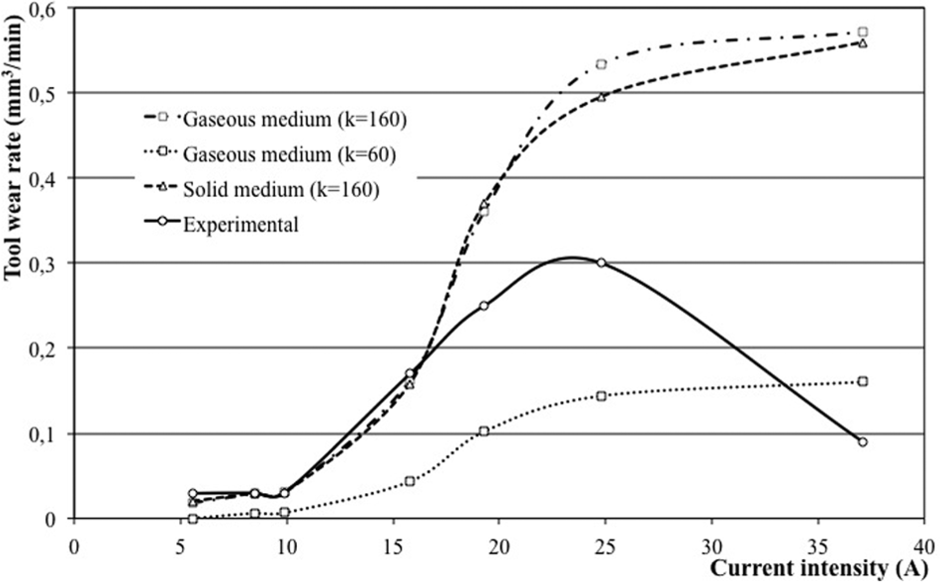
Comparison between numerical and experimental tool wear rate.
On the one hand, the tool wear rate is affected by the thermal conductivity of the plasma channel, because the numerical results show that the tool wear rate obtained using the plasma channel in gaseous medium with high thermal conductivity is higher than the tool wear rate obtained using the plasma channel in gaseous medium with low thermal conductivity. So, the melting and evaporation of tool’s material are accelerated for a plasma channel with high thermal conductivity. On the other hand, the thermal unbalance used in the method can explain the divergence between numerical and experimental data, because the material evaporation of the electrodes corresponds to an unbalance of 13% and can be higher due to high speed of material evaporation during the electrical discharge. Moreover, the open voltage is very important in the EDM performance as shown in the research by Fonseca and Marafona, 9 where the open voltage was pre-set at 100 V to compute the performance of the electrodes for 37.1 A discharge current, leading to low electrical potential gradient to remove the electrodes’ material.
The numerical results of tool wear rate show that the plasma channel developed in solid and gaseous mediums are both possible in EDM, due to the high degree of agreement with the experimental data of machining performance.
The numerical results of the material removal rate show a similar behavior to tool wear rate, which can thus be explained using some of the same statements of tool wear rate behavior. So, on the one hand, the numerical results of material removal rate obtained using plasma channel developed in the gaseous medium with low thermal conductivity are smaller than experimental data, the exception being at 37.1 A current intensity. On the other hand, the numerical results of material removal rate obtained using the plasma channel developed in solid medium are in agreement with experimental data from 5.6 A until 24.8 A, the numerical value of the material removal rate being higher than the experimental value for the 37.1 A current intensity, as can be seen in Figure 4. Thus, the large difference between the numerical results and experimental value for 37.1 A current intensity is mainly due to the open voltage of 180 V used in the numerical simulation instead of the open voltage of 100 V, but also due to the low electrical potential gradient that does not allow to remove all the melted material.
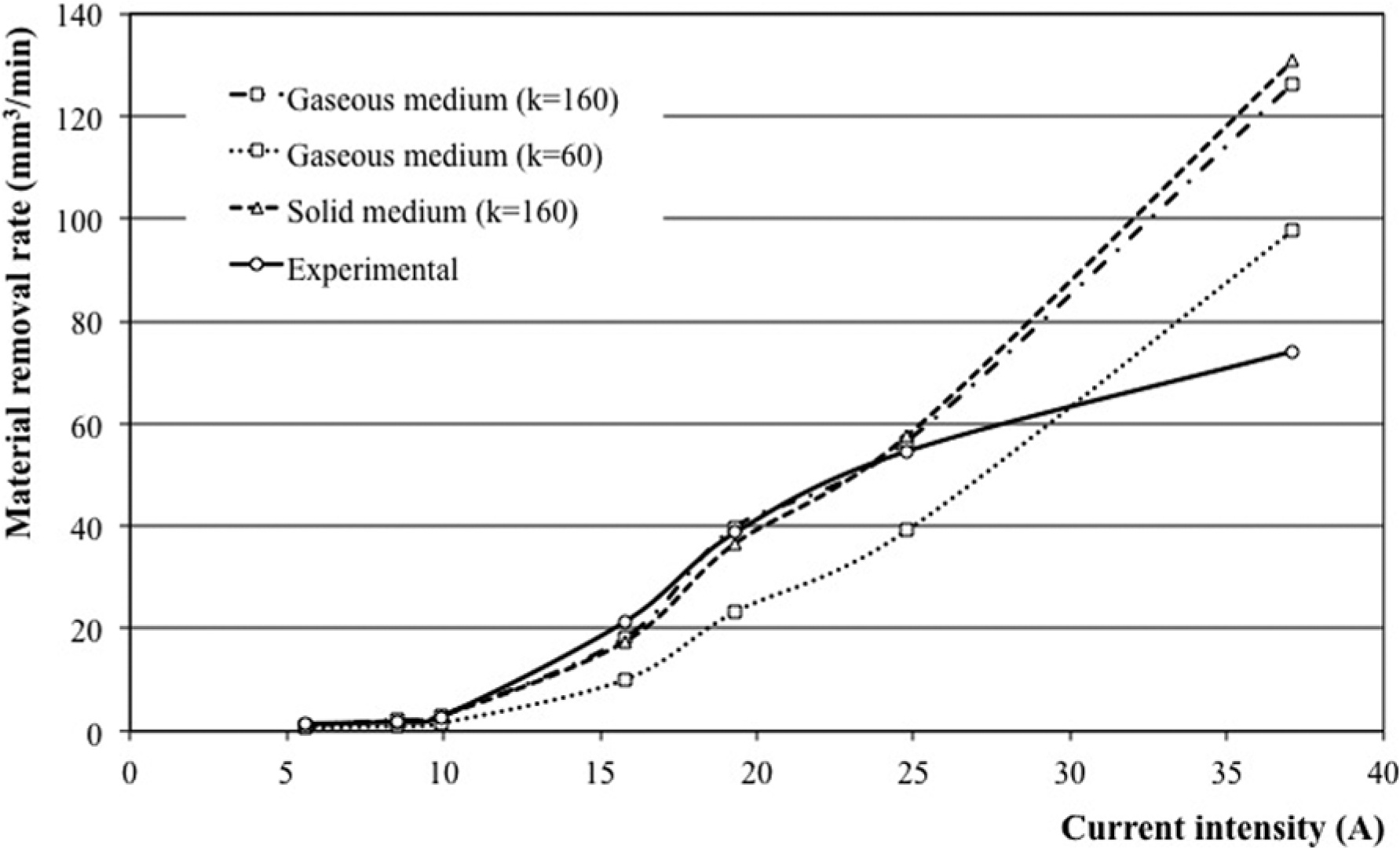
Comparing the numerical material removal rate and experimental data.
The numerical results of material removal rate obtained using plasma channel developed in gaseous medium with low thermal conductivity are lower than the numerical results of material removal rate for plasma channel developed in gaseous medium with high thermal conductivity. This statement demonstrates that material removal rate is lower when using deionized water instead of hydrocarbon oil, as mentioned in the researches by Koenig and Joerres 14 and Lui et al. 15 Thus, the breakdown of hydrocarbon oil leads to the creation of graphite, which sublimates due to the high temperature reached in the plasma channel. The presence of graphite in the plasma channel leads to a high thermal conductivity and simultaneously a high material removal rate.
The numerical results of material removal rate obtained using the plasma channel developed in solid and gaseous mediums are similar, but the material removal rate obtained using the plasma channel developed in gaseous medium with low thermal conductivity is significantly smaller than the material removal rate obtained using plasma channel in gaseous medium with high thermal conductivity, which means that the gaseous medium with low thermal conductivity is a good approach to simulate deionized water as dielectric.
There is a similarity between the numerical results of material removal rate obtained using plasma channel developed in solid and gaseous mediums and the experimental data, which means that, both cases can occur in the EDM, or in other words, it is possible that the electrical discharge ignition occurs in a gas bubble or in a chain of graphite particles.
Conclusion
The numerical results of the EDM performance obtained using the plasma channel developed in gaseous and solid mediums are in agreement with the experimental data, showing that the electrical discharge can be developed in gaseous or solid medium when the dielectric is hydrocarbon oil. The electrical discharge ignition in gaseous and solid mediums is reliable in EDM, or in other words, the electrical discharge ignition can occur in a gas bubble or in a chain of graphite particles, as demonstrated through numerical and experimental analyses of the EDM performance. Therefore, the breakdown of hydrocarbon oil generates particles of graphite and bubbles of gas during EDM, leading to a plasma channel with electrical and thermal conductivity of the carbon.
The main conclusion is that the ignition of electrical discharge can occur in solid and gaseous mediums in EDM; this work demonstrates it numerically and experimentally through the evaluation of EDM performance.
The electrical resistivity is the main cause of the plasma temperature because the radii of plasma channel increase leading to an increase in the electrical resistivity the heat energy of the pulse being maintained to remove material.
The micro-particles of graphite, solid medium, act as ignition of electrical discharge, leading the electrical and thermal conductivity of the carbon to the plasma channel in the EDM.
The electrical discharge is developed in gaseous medium or gas with carbon properties when the dielectric is hydrocarbon oil, and thus, the plasma channel has electrical and thermal conductivity of the carbon.
The EDM plasma developed in gaseous or solid medium is reliable when the dielectric fluid is hydrocarbon oil, as shown in the numerical and experimental analyses of the EDM performance.
Footnotes
Declaration of conflicting interests
The author(s) declared no potential conflicts of interest with respect to the research, authorship and/or publication of this article.
Funding
The author(s) received no financial support for the research, authorship and/or publication of this article.