
Abstract
In this article, a new manufacturing method is introduced to shape circular tubes into columns with triangular cross-section by the elastoforming process. Also, a theoretical analysis is performed to derive a theoretical formula for predicting total dissipated energy that is required for the forming process. For this purpose, V-shape dies with different angles are designed and some aluminum and brazen tubes with different characteristics are prepared. The circular tubes in the empty and filled conditions are compressed between a rigid V-shape die and a flat punch, and during the plastic deformation under the lateral loading, the tubes are shaped into the triangular sections. Considering different tube lengths, outer diameters and wall thicknesses, the specimens are categorized. Also, some of the samples are filled by cylindrical polyethylene Teflon with different thicknesses to investigate the effects of Teflon-filler on the shaping process of the triangular columns. The experiments show that using the cylindrical Teflon-filler, deformation mode of the triangular tubes improves, significantly. In addition, experimental observations of the deformation modes illustrate that there is an optimum value for wall thickness of cylindrical Teflon-filler and the tubes with the optimum Teflon-filler forms close to desirable triangular shape. The results show that by increasing tube wall thickness, probability of crack initiation and fracture reduces. Furthermore, comparison of estimations by the presented theory and the corresponding experimental measurements show an acceptable agreement, in both of empty and filled conditions.
Keywords
Introduction
By developing engineering sciences, new methods for manufacturing industrial products with suitable quality and with the less cost have been introduced. Today, various forming methods such as casting, hydroforming, spinning, cold metal forming and explosion forming are used to produce different products. During the mentioned forming methods, cold metal forming is introduced as an economic process.
Reshaping process of non-circular pipes is more significant because of their various utilizations in structural elements and also for designing a series of roll profiles and deciding the amount of deformation and peripheral reduction of cross-section. Due to complicated deformation behaviors of pipes during reshaping, the design procedures for rolls and forming mainly rely upon experience-based knowledge. 1 One of the important factors in the forming process is to form a simple tube into a die cavity of complex shape with varying cross-sections without causing any defects such as bursting, wrinkling or buckling. 2 Triangular tubes are used as lightweight structural elements of engineering applications and also, in transmission line such as heat exchanger and chambers. Also, this kind of tube has several constructional advantages in comparison with rounded tubes because of their geometry shape and weight. There are some researches on heat transfer advantages of triangular columns in field of fluids mechanics. For examples, Gunes et al. 3 have experimentally investigated heat transfer and pressure drop in a coiled wire inserted tube in turbulent flow regime. The coiled wire was equilateral triangular cross-section and was inserted separately from the tube wall. Wang and Dong 4 used bundles of triangular tubes for constructing models of interacting capillaries which allow the wetting phase to reside in the edges.
In recent decades, large plastic behavior of mechanical elements such as tubes and columns subjected to various types of load has been subject of several experimental and theoretical researches. 5 Olabi et al. 6 presented an overview of energy absorbers in the form of tubes. The common modes of deformation such as lateral and axial compression, indentation and inversion were reviewed. Siyahpoosh and Niknejad 7 introduced a new theoretical deformation model during the contraction process as a cold metal forming process and calculated absorbed energy and instantaneous axial force of empty tubes with circular cross-section during the axial contraction progress using a rigid conical die. Niknejad et al. 8 investigated axial compression process of foam-filled rectangular columns in the quasi-static condition by theoretical and experimental methods. Hong et al. 9 studied triangular tubes as an absorber and they explored plastic deformation modes of triangular tubes under quasi-static axial compressions. Also, Hong et al. 10 designed and manufactured multi-cell tubes with triangular and Kagome lattices to enhance energy absorbing ability of thin-walled structures. Wang et al. 11 studied collapse mechanism and energy absorbing ability in lateral compression process on metallic isosceles triangular tubes with different base angles.
Furthermore, there are a few researches on shaping process of rounded tubes into the non-circular cross-sections. Nefussi and Gilormini 12 predicted the optimal shape and the deformed length of a metal sheet during cold-roll forming, before the first roll stand. The developed approach for the cold-roll forming of elasto-plastic materials was applied for circular tubes. Nefussi et al. 13 considered the sheet to be transformed as a thin shell and its middle surface as a Coons patch. Bayoumi 14 investigated a solution for the problem of cold forming of regular polygonal tubular sections from rounded tubes, analytically. Hwang and Altan 15 evaluated the quality and plastic patterns of the tubes formed into regular triangular cross-section by hydraulic expansion and crushing process combined with hydroforming. Then, Hwang and Altan 16 discussed the effects of forming procedures of circular tube into a rectangular cross-section for hydraulic expansion alone and crushing processes combined with preforming and hydroforming upon the forming pressures, clamping forces and the thickness distributions of the formed parts. Sahoo et al. 17 tried to use spatial elementary rigid region (SERR) technique for analyzing round-to-triangle extrusion through a converging die. Hwang and Chen 18 proposed a simple analytical expression which can be used easily in a manufacturing plant to estimate forming pressure, and to explore plastic deformation behavior of tubes during hydraulic expansion process in a rectangular cross-sectional die. Hwang and Altan 19 evaluated quality of tubes formed by process fusion. Plastic flow patterns and thickness distribution of formed product were explored during shaping process of a circular tube into a square cross-section. Hwang and Chen 20 proposed a mathematical model considering sliding friction between the tube and die to explore the plastic deformation behavior of the tubes during a hydraulic expansion process in a square cross-sectional die. In order to reduce labor and time for making new products, Moslemi Naeini et al. 1 developed a new roll design method. The method was based upon the simulation technique by which analyses two-dimensional elasto-plastic deformations of the cross-sections of pipes and the pipe with the pentagonal cross-section. Yang and Ngaile 21 introduced a mechanics-based analytical model for planar tube hydroforming of both irregular and regular polygon shapes. Abrinia and Farahmand 22 used a new solution based on upper-bound method to solve three-dimensional (3D) problem of reshaping of thick square tube from a round one. Bayoumi and Attia 23 determined the forming tool load in plastic shaping of a round tube into a square tubular section analytically and also numerically by applying finite element simulation. Yuan et al. 24 investigated filling behavior of a transition corner by theoretical analysis and also, with experimental and finite element method for a rectangular column during the hydroforming process. Also, they analyzed cracking mechanism of transition region between the straight side and the corner. Zhu et al. 25 investigated effects of a polyvinyl chloride (PVC) mandrel on the forming quality of rectangular tubes, such as tube damage distribution, wall thickness variation, section deformation and spring-back, comparing with the traditional mandrel-cores die. Recently, Rahmani and Niknejad 26 introduced a manufacturing method for creating a fold with a controllable and certain wavelength into circular metal tubes during the axial compression.
In this article, a new experimental method is introduced to shape the circular tubes into the columns with the triangular cross-section by the elastoforming process instead of hydroforming or other forming methods. Also, a theoretical analysis is performed, based on energy method to calculate total energy that is required for shaping process of circular-into-triangular column. For this purpose, a V-shape die is designed and lateral load is applied by a rigid punch on circular tubes with cylindrical polyethylene Teflon-filler and the triangular column is produced during the compression between the rigid punch and the V-shape die. Then, the effects of geometrical characteristics are investigated on deformation mode and dissipated energy during the shaping process. Also, theoretical estimations of dissipated energy are compared with the corresponding experimental results to investigate verity of the theory.
Experiment
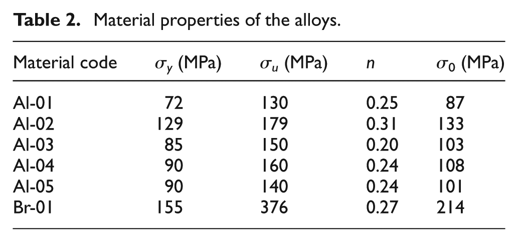
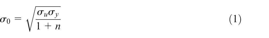
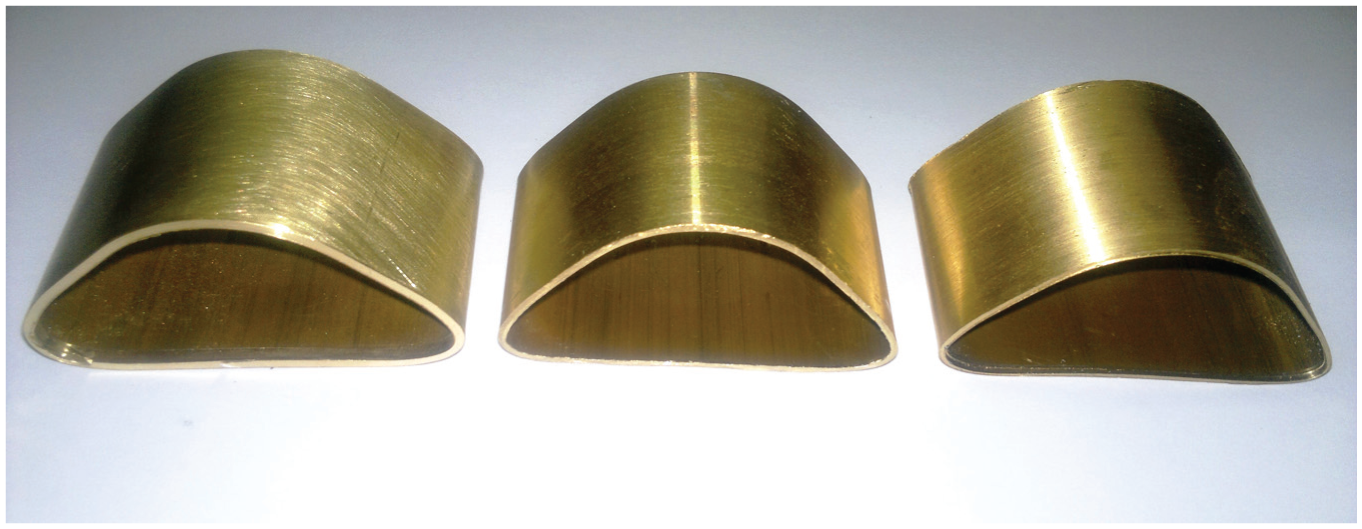
Figure 1(a) illustrates a rounded tube with cylindrical Teflon-filler during the lateral compression, schematically. In the experimental part of this research, some circular tubes of aluminum and brass alloys were prepared and used in quasi-static compression tests in the lateral direction to reshape the circular tubes into the triangular columns. On the other hand, during the experiments, the columns with triangular cross-section are produced by compressing the rounded tubes between a V-shape die with different apex angles and a flat punch via the elastoforming method. The rounded specimens were prepared with different wall thicknesses, lengths and diameters of the tubes and also, some specimens were filled by the cylindrical polyethylene Teflon (with industrial name of polytetrafluoroethylene (PTFE)) with the different wall thicknesses to study the effects of geometrical parameters on the columns formability during the elastoforming process. All the experiments were carried out by a DMG machine, model 7166. Loading rate of the machine was regulated at 5 mm/min, constantly. Three types of V-shape die with the different apex angles of 70°, 90° and 100° were produced by a computer numerical control (CNC) machine. Geometrical characteristics, mass and material types of the rounded specimens and Teflon-fillers are reported in Table 1. In the table, D, t, L and m are outer diameter, wall thickness, length and mass of the tubes, respectively. Also, D′, t′, L′ and m′ indicate outer diameter, wall thickness, length and mass of the cylindrical polyethylene Teflon-filler, respectively. Figure 1(b) illustrates a produced triangular aluminum column with the cylindrical polyethylene Teflon-filler after the elastoforming process. Table 2 gives material properties of the circular tubes.
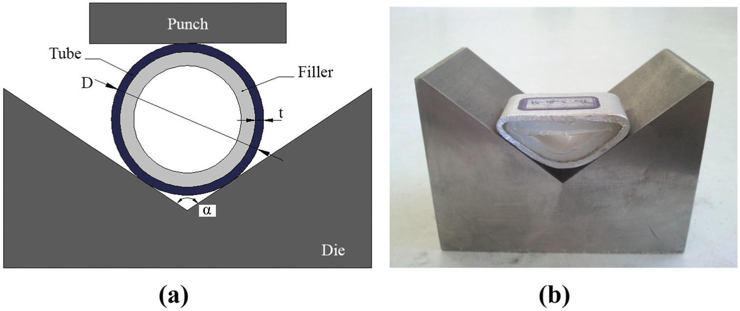
(a) A schematic pattern of a Teflon-filled tube before the forming process and (b) a produced triangular aluminum column in the filled condition after the forming.
Geometrical dimensions and mass of the tubes and the polyethylene Teflon-filler.
Material properties of the alloys.
The main purpose of manufacturing processes is the production of high quality products with the least costs and the desirable quality. In this work, a new method of triangles tube forming is considered which is based on cold forming method. In this method, to reshape the rounded tubes to triangle ones, a V-shape die with lateral loading condition is just needed. Cylindrical polyethylene Teflon as filler is a gettable material which is used in the process. Polyethylene Teflon (PTFE) has several applications in different industries which need low friction. Also, it can be used as coating material for several applications. Due to the property of Teflon spring-back and its mechanical properties, using the Teflon-filler may prove final shape of triangle tubes, so it is investigated in this research work.
Theory
By compressing a rounded tube on a V-shape die with angle of α, tube is deformed according to Figure 2(a). Also, Figure 2(b) and (c) illustrates theoretical model of deformation mode and volume element, respectively, that is considered in this theory. The main aim of the theory is to derive an analytical relation to estimate the total dissipated energy during the shaping process of empty and Teflon-filled circular tubes into the triangular column. Therefore, mechanical behavior of the tube is considered as the rigid-perfectly plastic material with flow stress of Santosa et al. 27
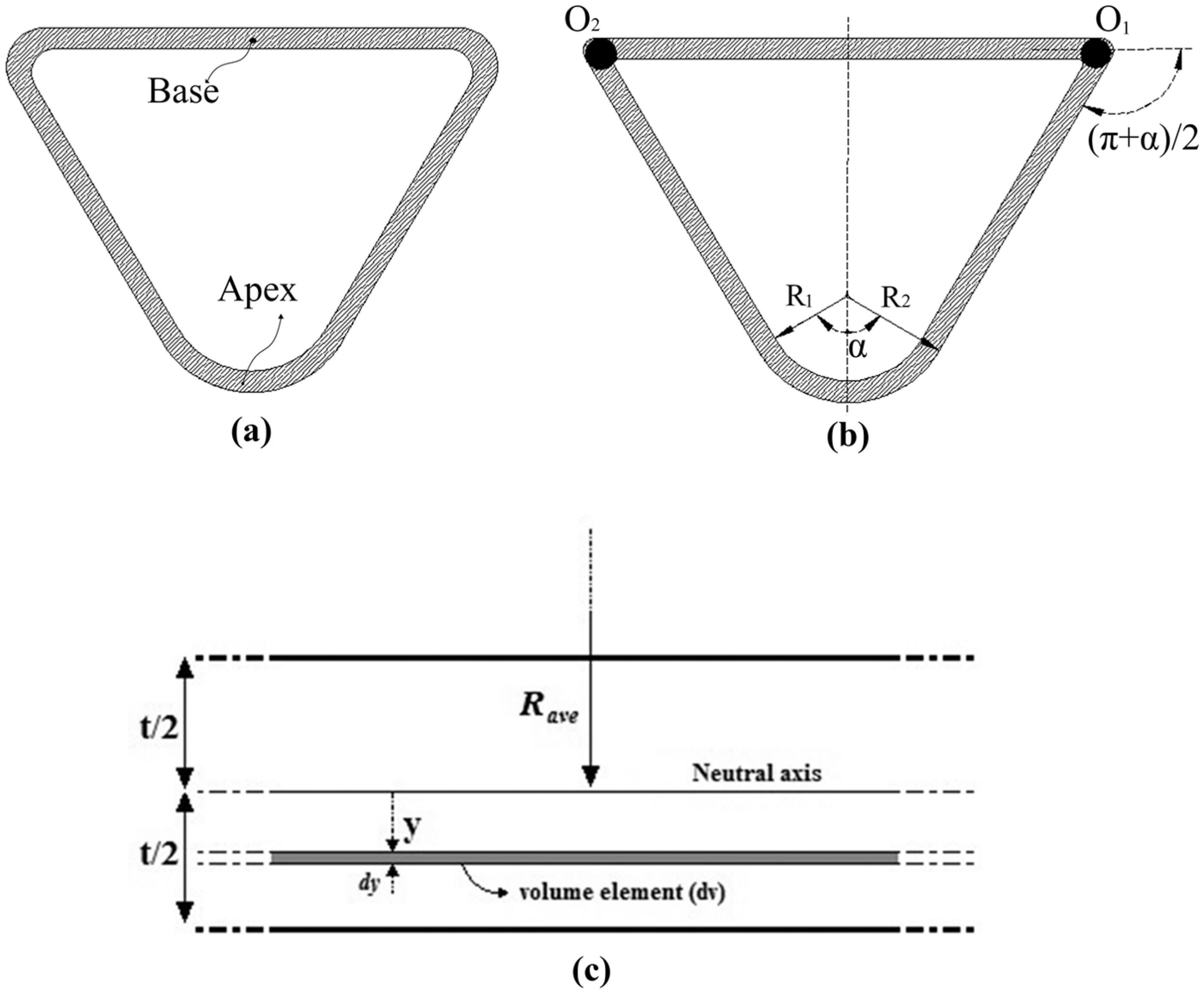
Schematic shape of triangular column after the forming process: (a) real specimen, (b) theoretical deformation model and (c) geometrical characteristics of a volume element.
In the above relation, σu and σy indicate ultimate and yield strengths and n is work hardening exponent of tube material.
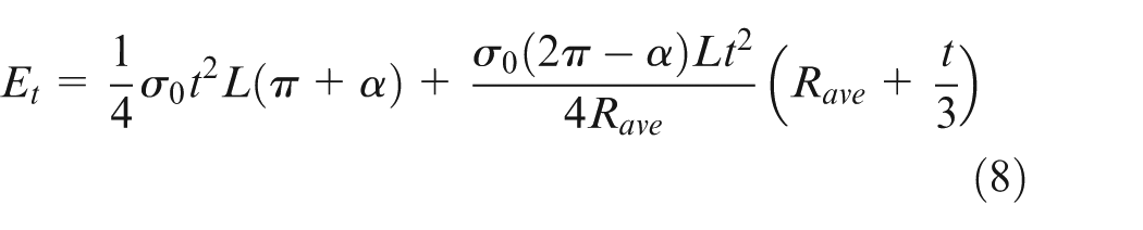
In the forming process, the kinetic energy of the performed work by the external load is dissipated by two different mechanisms: two plastic hinge lines and unbending some parts of tube wall. As shown in Figure 2(b), according to the considered theoretical deformation model, during the shaping progress, two plastic hinge lines are formed at points O1 and O2. Generally, dissipated energy by a limit rotation equal to θ around a plastic hinge line with the length of c is equal to

where M is fully plastic bending moment per unit of bending length and is equal to
In the above relation, t is tube wall thickness. During the shaping progress of a circular tube into a triangular column, the rotation angle around each plastic hinge line is equal to (π + α)/2; where α is apex angle of the die. Therefore, summation of the dissipated energies by two plastic hinge lines during the forming process is calculated as
During the shaping progress of the circular tubes into the triangular columns, the kinetic energy is dissipated by the unbending process of some parts of the tube wall, too. It means that curvature radius of some parts of the tube wall changes from Rave to infinity; where Rave is mean radius of the initial circular tube. The dissipated energy due to the unbending mechanism is calculated as
In the recent relation, dv is a volume element of the part of tube wall that is unbent and according to Figure 2(c) is obtained as

Therefore, by considering the strain component equal to y/Rave, the dissipated energy by the unbending mechanism is calculated as the following relation
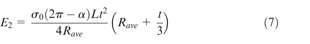
Finally, the total dissipated energy during the shaping process of the circular metal tubes into the corresponding triangular columns is calculated as
The experimental observations of the performed tests on the circular samples show that a part of the tube wall that is a circular arc in front of the die apex angle remains constant without any considerable deformation, approximately. Therefore, in this theory, the dissipated energy by the mentioned part of the tube wall is neglected. On the other hand, energy absorption by apex zone of triangular tube was neglected, because, the experiments show that no significant deformation occurs in the apex zone of triangular tubes.
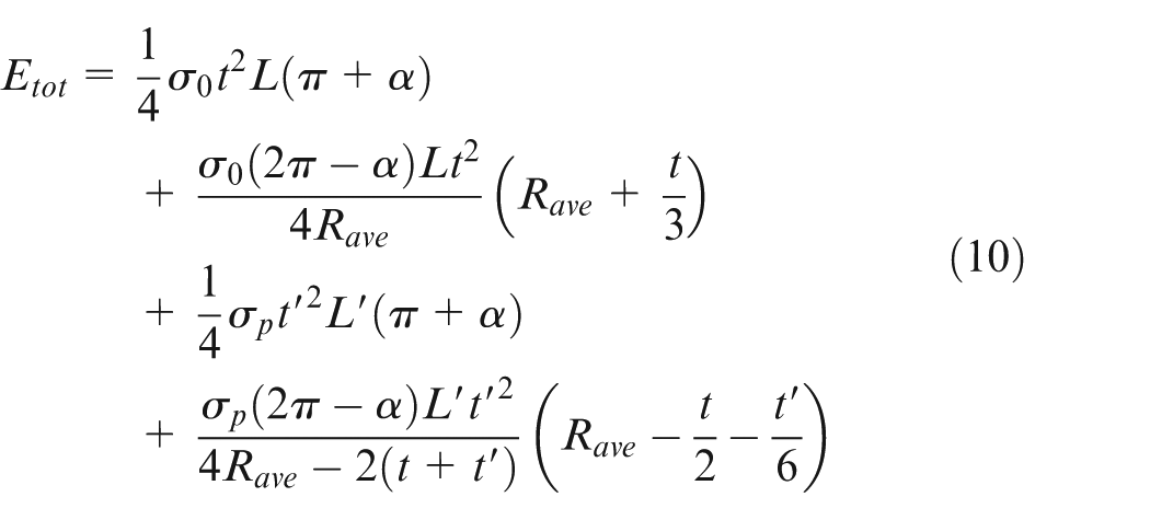
The cold forming process of this research works is performed in two different conditions: empty and Polyethylene Teflon-filled. Equation (8) estimates required energy for shaping a circular metal tube into a triangular section in empty condition. Experimental observations show that mechanical behavior and stress-strain relation of the filler during the standard compressive test on a solid cylindrical specimen of Teflon are according to the relation of σ = kεn; where, k and n indicate strength coefficient and strain hardening exponent, respectively. This theory is calculated to estimate the total absorbed energy during the forming process, so the area under the stress-strain diagram of the filler during the standard compressive test has the key role. Consequently, mean value of normal stress of the filler during the plastic deformations is considered as σp. On the other hand, the filler is considered as a material with constant plateau stress of σp during the forming process. The recent assumption does not have considerable effect on total forming energy by the filler. During the forming process on a Teflon-filled tube, plastic deformations of the filler correspond to deformation mode of the tube. Therefore, geometry and deformation mode of hollow cylindrical Teflon is considered similar to circular metal tube, during the forming process on a Teflon-filled tube. Thus, in equation (8), flow stress (σ0), initial length (L), wall thickness (t) and mean radius (Rave) of tube are replaced by plateau stress (σp), initial length (L′), initial wall thickness (t′) and mean radius (Rave−t/2 − t′/2) of Teflon to obtain the following relation for estimating dissipated energy by the Teflon during the shaping progress
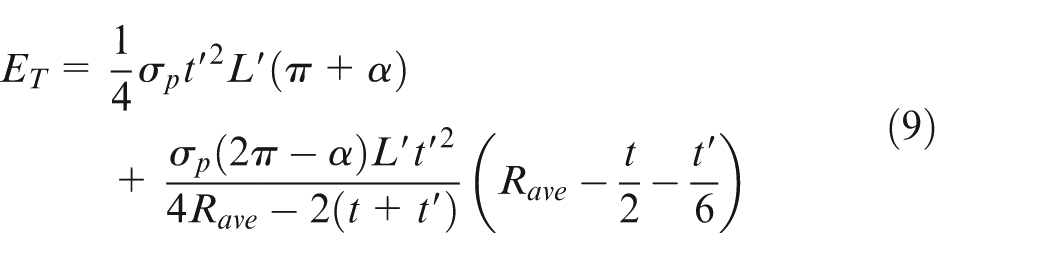
Finally, summation of dissipated energy by circular metal tube and Teflon-filler results in the following relation to predict total required energy for shaping process of a Teflon-filled tube into a triangular section under the axial compression loading between a rigid platen and a V-shape die
Results and discussion
Several compression experiments in the lateral direction were carried out on aluminum and brazen alloys with different dimensions to shape the circular tubes into the triangular columns. The specimens were categorized in empty and polyethylene Teflon-filled conditions. Some samples were filled by cylindrical polyethylene Teflon with different wall thicknesses.
Diagrams of lateral load, dissipated energy and specific dissipated energy (SDE) versus lateral displacement are sketched to investigate the effects of tubes diameter, wall thickness and length, and also, the effects of Teflon wall thickness on tubes formability during the shaping process. For each specimen, deformation mode of the tube during the shaping process is discussed. The desired triangular column has an apex angle which is equal to die apex angle and also, it has a straight base.
The main purpose of this work is to produce a metal column with triangular cross-section by the cold metal forming on a circular tube. At the end of the forming process, the final column shape must be exactly similar to the desirable triangular cross-sectional shape. To determine the performance of the suggested forming method, final cross-sectional shape of each triangular column is compared with the desirable shape. This is the most important comparison in this research. To perform a logical comparison, after the forming process, the corresponding empty and filled specimens are positioned concentrically, and schematic diagrams of their cross-sections are sketched. To evaluate the success of the performed forming process and perform a suitable comparison, some criteria are defined as the below:
Two formed corners of the triangular cross-section should have zero curvature radius;
Relative vertical distance between different points of the horizontal sides of the triangular column (base) should be zero;
Just two plastic hinge lines must be created in the base;
Apex angle of the produced triangular cross-section must be equal to the die apex angle.
To obtain value of total deviation (TD) with respect to the ideal cross-section, final triangular section of the tested specimens compares with the corresponding ideal shapes and value of geometrical deviations of the forming process are calculated. For this purpose and according to Figure 3, r1 and r2 are defined as curvature radiuses of the right and left corners of the triangular section, respectively. Also, Δ1 shows maximum deviation of the base midpoint with respect to an ideal straight line. In addition, Δα indicates difference of the apex angle value of the triangular section with respect to the die apex angle. As a simple criterion of deviation, summation of the mentioned deviations are defined as TD and it is calculated as TD = Δ1 + |Δα| + r1 + r2. It is obvious that if the recent defined quantities are approximated to zero, the final deformation mode tends to the ideal form. One of the most important parameters in shaping process on a circular tube into the triangular column is just creating two plastic hinge lines in the columns and consequently, forming the triangular section base as a straight line. It means that between the different defined parameters of deviation, Δ1 is the most important and must be close to zero.
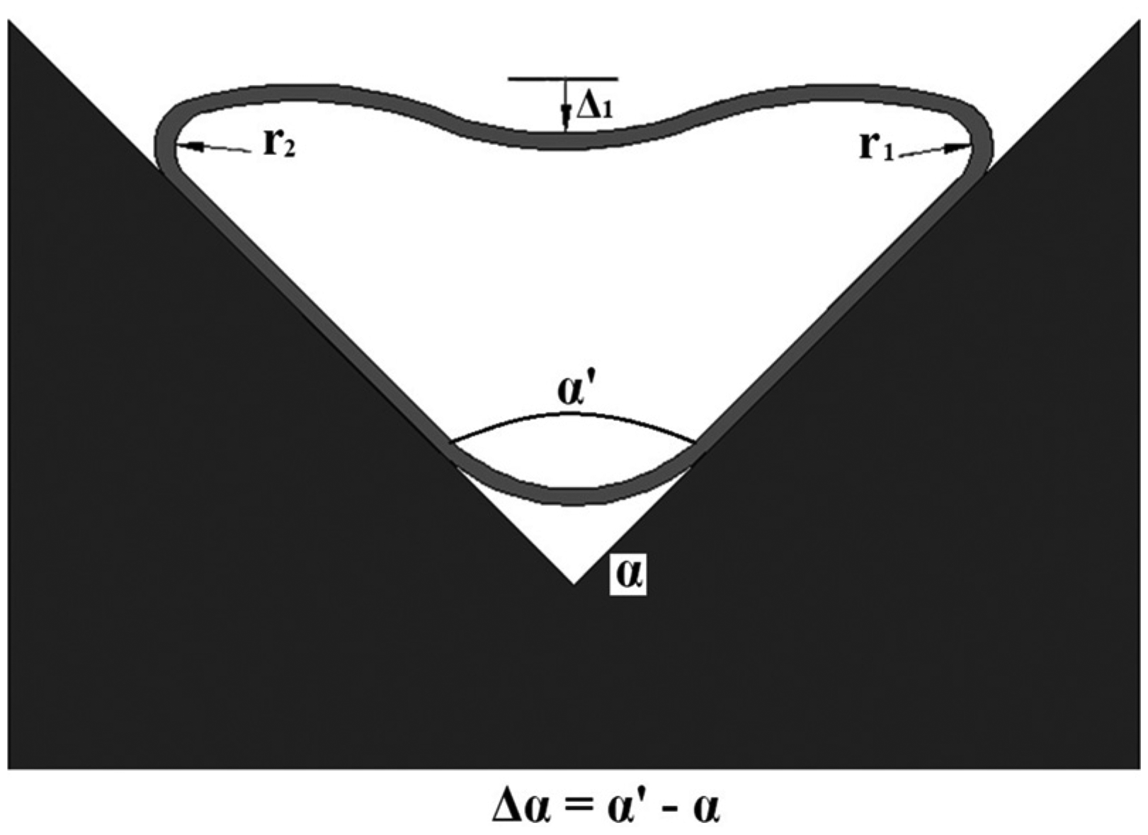
Schematic shape of the triangular section.
Effects of Teflon-filler
To study the effects of Teflon-filler on the dissipated energy and deformation mode of the shaping process, some specimens were prepared and tested in both of the empty and filled conditions. Figure 4 illustrates the dissipated energy-displacement and dissipated energy/mass-displacement diagrams of the specimens Tri-35-20 and Tri-35-17 with the die apex angle of 100°. The mentioned samples were shaped in different conditions of empty and cylindrical Teflon-filled of 4.5 mm wall thickness, respectively. The curves in Figure 4(a) show that the required kinetic energy for shaping the Teflon-filled tube is higher than the empty one. By filling the tubes with the Teflon, the dissipated energy and mass of the structure increase. SDE is defined as ratio of dissipated energy per unit of mass. The sketched diagram of energy/mass ratio versus the lateral displacement in Figure 4(b) shows that energy/mass ratio of the filled sample is higher than the empty one.
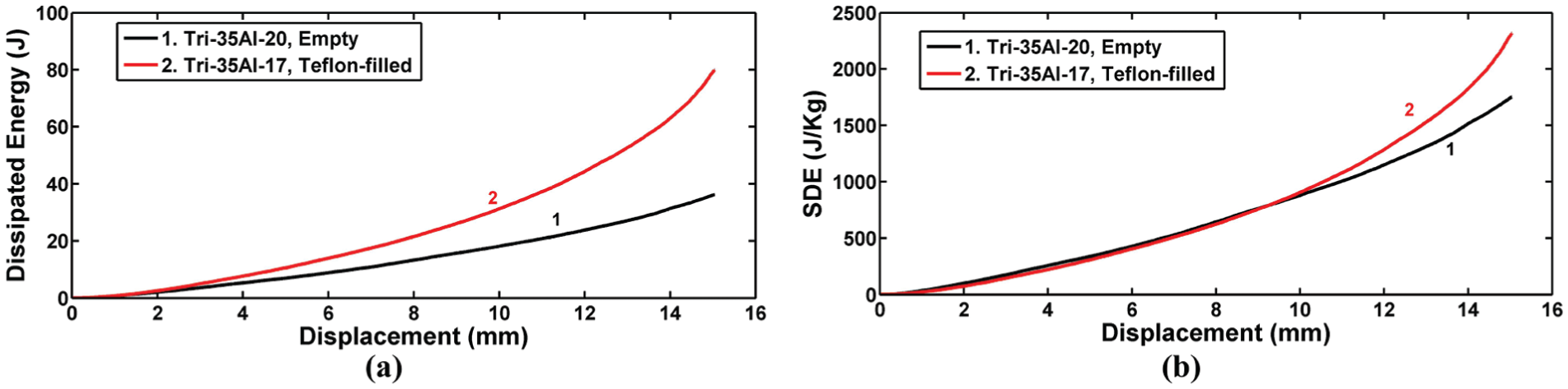
Diagrams of the specimens Tri-35-20 and Tri-35-17 with the die apex angle of 100°: (a) dissipated energy-displacement and (b) specific dissipated energy-displacement.
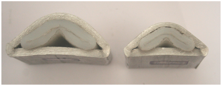
To investigate the effects of Teflon-filler on the deformation mode of the forming process, Figure 5(a) compares the empty and filled specimens Tri-35-20 and Tri-35-17 with the same sample characteristics and with the die apex angle of 100°.
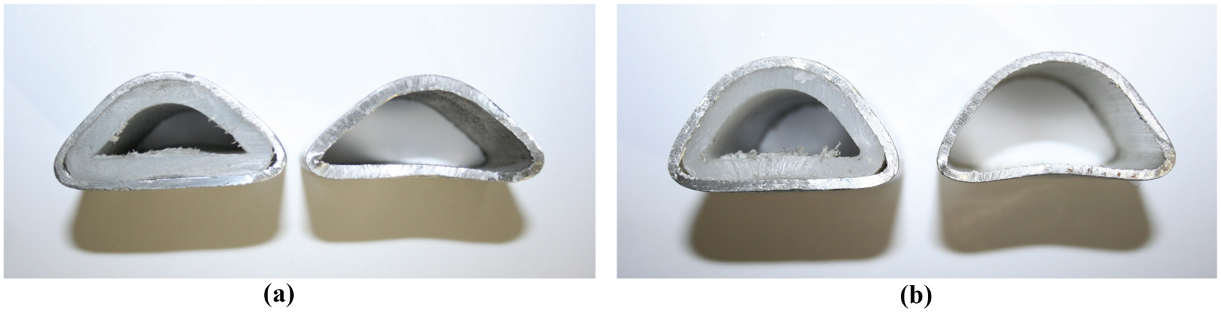
Comparison between the deformation modes of the empty and Teflon-filled samples: (a) the specimens Tri-35-20 and Tri-35-17, (b) the specimens Tri-35-22 and Tri-35-19.
Measurements of dimensions of the triangular section final shape show that in the empty specimen Δ1 = 1 mm, Δα = +2°, r1 = 2.3 mm and r2 = 2.0 mm. Also, in the corresponding filled sample, different deviations are Δ1 = 0.05 mm, Δα = −1°, r1 = 2.3 mm and r2 = 2.4 mm. Therefore, the TD of the empty and filled samples are respectively equal to 7.3 and 5.75. Also, it is found that the presence of the Teflon cylinder into the circular tubes causes a considerable reduction in Δ1 from 1 to 0.05 mm. It shows that filling the tubes by the Teflon-filler improves the final shape of the produced column.
As another example, Figure 5(b) illustrates the final shape of the empty and filled specimens Tri-35-22 and Tri-35-19 that were formed on a rigid die with the apex angle of 70°. Measurements show that deviation parameters of Δ1, Δα, r1 and r2 of the empty samples are 1.5 mm, +1°, 3.1 and 3.1 mm and the corresponding quantities of the filled one are 1.0 mm, +1°, 3.1 and 3.1 mm, respectively. Therefore, TDs of the empty and filled samples are 8.7 and 8.2. Comparison of the final shapes of the empty and filled samples show that in all the experiments, TD of the filled sample is less than the corresponding empty one and also, filling the tubes by the Teflon-filler prevents from creating an additional plastic hinge line at the base midpoint.
Effects of Teflon-filler wall thickness
Figure 6 shows diagram of lateral load versus the lateral displacement of the specimens Tri-30-01, Tri-30-02, Tri-30-03, Tri-30-04 and Tri-30-05 during the forming process. The specimens have different Teflon wall thicknesses and the same tube characteristics. The specimens Tri-30-01, Tri-30-02, Tri-30-03 and Tri-30-04 were filled by the cylindrical Teflon-filler with the thicknesses of 3.2, 4.9, 6.8 and 9.2 mm, respectively and the specimen Tri-30-05 was filled by a solid Teflon rode. Teflon wall thickness ratio of the specimens Tri-30-01 and Tri-30-02 is equal to 1.63 and at the same lateral displacement of 3 mm, their corresponding load ratio is 1.88. Similarly, Teflon wall thickness ratio of the specimens Tri-30-01 and Tri-30-03 is 2.26 and their corresponding load ratio is equal to 2.98. Also, Teflon wall thickness ratio of the specimens Tri-30-04 and Tri-30-05 with respect to the specimen Tri-30-01 are 3.06 and 4.25 and their load ratios are 4.29 and 6.21, respectively. The performed comparisons show that by increasing the filler wall thickness, the required lateral load of the shaping process increases nonlinearly.
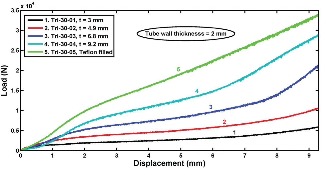
Load-displacement diagram of the specimens Tri-30-01, Tri-30-02, Tri-30-03, Tri-30-04 and Tri-30-05 with the die apex angle of 90°.
Also, experimental measurements indicate that the total dissipated energy during the forming process of the specimens Tri-30-01, Tri-30-02, Tri-30-03 and Tri-30-04 are equal to 45.1, 96.43, 156.15 and 519.685 J, respectively. Also, the SDE of the mentioned specimens are obtained as 2061.24, 3545.22, 4908.83 and 15,320.9 J/kg, respectively. It means that when the thicker polyethylene Teflon cylinder is used into the circular tube as the filler, the shaping progress has higher SDE.
Deformation modes of the specimens Tri-30-01, Tri-30-02, Tri-30-03, Tri-30-04 and Tri-30-05 after the manufacturing process on a rigid die with the apex angle of 90° are illustrated in Figure 7. A desired column is a triangular section with a straight base and a right apex angle. According to the figure, in the specimens Tri-30-05 and Tri-30-04 with the thicker Teflon wall, there is an undesirable curvature in their bases. Furthermore, base of the specimen Tri-30-02 (Figure 7d) is approximately straight and also, its apex angle is the nearest angle to 90°, comparing with the other samples. Also, the experimental observations indicate that there is an optimum value for the wall thickness of the cylindrical Teflon-filler and the best forming process occurs in the specimens with a Teflon wall thickness of 10%–15% of the tube inner diameter. As a numeric comparison, and according to the dimension measurements of the columns final shape, TDs of the specimens Tri-30-01, Tri-30-02, Tri-30-03, Tri-30-04 and Tri-30-05 are respectively equal to 6.9, 6.8, 9, 14 and 18. Figure 8 illustrates experimental diagram of TD of five different specimens versus Teflon wall thickness. The reported results in the figure and experimental measurements show that the specimen Tri-30-02 has the minimum TD and also, its Δ1 is equal to zero. This figure proves that there is an optimum value for wall thickness of hollow cylindrical Teflon-filler to achieve the best deformation mode and the least TD.
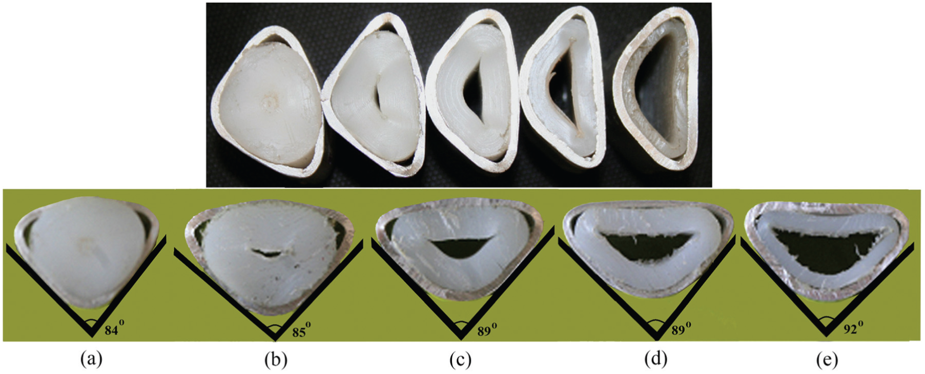
Deformation modes of the specimens Tri-30-05, Tri-30-04, Tri-30-03, Tri-30-02 and Tri-30-01 after the cold forming process with the die apex angle of 90°.
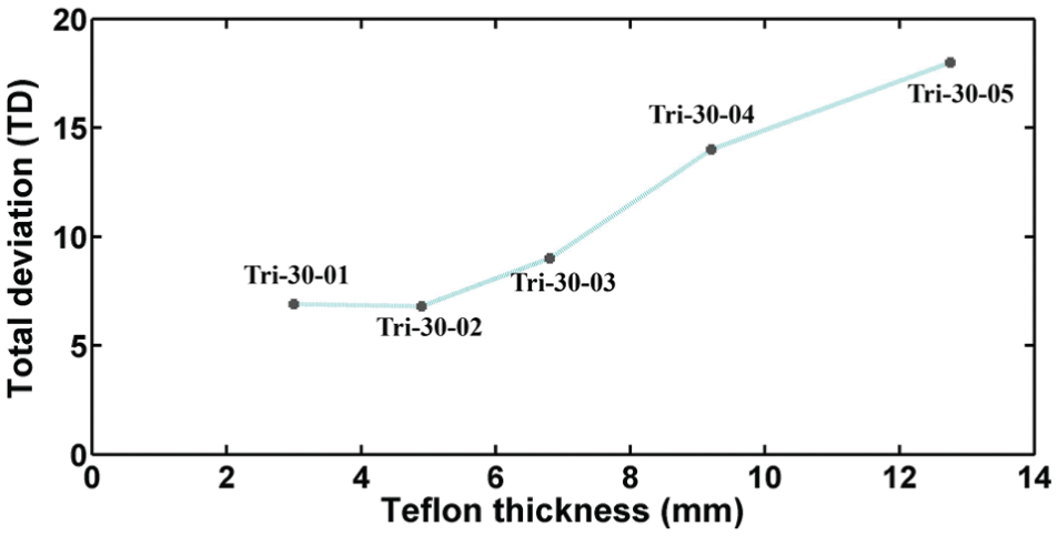
Total deviation of the specimens Tri-30-01, Tri-30-02, Tri-30-03, Tri-30-04 and Tri-30-05 versus Teflon wall thickness.
Effects of tube wall thickness
Some circular aluminum and brazen tubes in the empty and Teflon-filled conditions and with the same inner diameter and length, but with different wall thicknesses were prepared and used in the elastoforming process to investigate the effects of tube wall thickness on the process. Figure 9 compares the SDE of the empty aluminum specimens Tri-40-26, Tri-40-27, Tri-40-28 and Tri-40-29 with the same inner diameter of 29.5 mm and nominal length of 42 mm, but with different tube wall thicknesses of 5.3, 4.0, 2.7 and 1.8 mm. The tubes were used in the shaping process on a rigid die with the apex angle of 100°. The figure shows that in the tubes with the inner diameter of 29.5 mm, by increasing the tube wall thickness, ratio of the dissipated energy/mass increases, too. Also, maximum load of the specimens Tri-40-26, Tri-40-27, Tri-40-28 and Tri-40-29 are 51.82, 26.60, 13.28 and 3.48 kN at the final displacement.
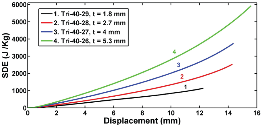
Diagram of specific dissipated energy versus displacement of the specimens Tri-40-26, Tri-40-27, Tri-40-28 and Tri-40-29 with die apex angle of 100°.
To study influences of tube wall thickness of Teflon-filled specimens on the forming process, the specimens Tri-50-14, Tri-50-15 and Tri-50-16 with the same inner diameter and length were filled by the same cylindrical Teflon-filler of 3.9 mm wall thickness. Wall thicknesses of the mentioned tubes are different and equal to 3.0, 4.0 and 4.7 mm, respectively. So, in the mentioned samples, wall thicknesses of the tubes are different and their other corresponding conditions are the same. Experimental measurements show that the specimen with the thicker tube wall thickness has higher forming energy level. Also, as a numeric comparison, tube wall thickness ratio of the specimens Tri-50-14 and Tri-30-15 is 1.33, and at the same displacement of 4 mm, their corresponding load ratio is 3.16. Similarly, wall thickness ratio of the specimens Tri-50-14 and Tri-50-16 is 1.56 and their corresponding load ratio is 4.38. It means that there is a nonlinear relationship between the tube wall thickness and the lateral load during the shaping process.
Figure 10 compares the final shapes of the empty aluminum specimens Tri-40-26, Tri-40-27, Tri-40-28 and Tri-40-29 with the same material type, inner diameter of 29.5 mm and nominal length of 42 mm, but, with different tube wall thicknesses of 5.3, 4.0, 2.7 and 1.8 mm, respectively. The figure shows the fracture process at a corner of the specimens Tri-40-29 with less wall thickness. The results indicate that apex angles of the mentioned specimens are the same. But, by decreasing the tube thickness, the probability of the crack initiation in the triangular column corners increases. The performed tests illustrate that by decreasing the tube wall thickness, an undesirable curvature appears in the triangular section base and consequently, an additional curvature occurs in the plastic hinge lines and it is a reason of the column corner fracture. On the other hand, by thinning the tube wall, the curvature radius of the produced column corners decreases, intensively and so, according to the relation of ε = y/ρ, where ρ is curvature radius and y is perpendicular distance from neutral axis, the maximum normal strain (ε) in the tubes with the thinner wall thickness may increase, due to the intensively curvature radius reduction. Therefore, the introduced cold metal forming process is suggested to form the tubes with thick-walled or thin-walled tubes made from materials with high ductility.
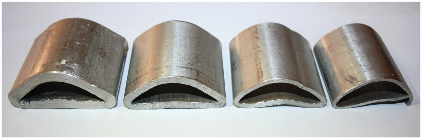
The specimens Tri-40-26, Tri-40-27, Tri-40-28 and Tri-40-29 after the forming process with die apex angle of 100°.
In this research work, the brazen specimens Tri-50-25, Tri-50-24 and Tri-50-23 (Figure 11) respectively with different tube wall thicknesses of 1.8, 1.6 and 1.2 mm were prepared and used in the shaping process and it was considered that no fracture occurs in the brazen samples and so, it is concluded that using the tubes with higher ductility in the introduced forming method, the fracture is eliminated.
The specimens Tri-50-25, Tri-50-24 and Tri-50-23 after the forming process.
Effects of tube length
In experimental part of this research work, some specimens with different initial lengths and with the same other properties were used in the elastoforming process to investigate the tube initial length influence on the forming process. Figure 12(a) illustrates experimental diagram of the load/length versus the lateral displacement of the specimens Tri-30-01, Tri-30-06 and Tri-30-07. The specimens have different lengths of 21.3, 38.7 and 59.6 mm and with the same other characteristics. The figure shows that the lateral load has a direct relation versus the tube initial length. For example, at the lateral displacement of 3 mm, length ratio of the specimens Tri-30-07 and Tri-30-06 is equal to 2.8 and their load ratio is 2.8, too. Therefore, in the shaping process of the circular tubes into the triangular sections, the samples with different lengths have the same SDE and the required load and energy for the shaping process linearly increase, by enhancing the sample length.
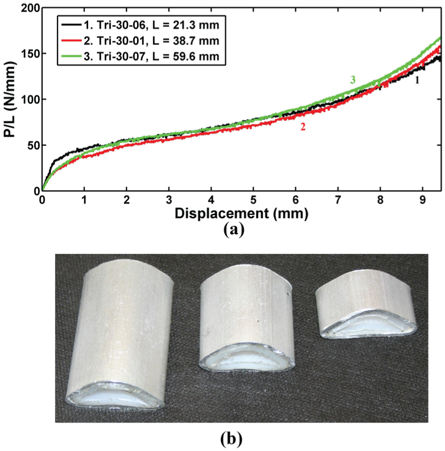
(a) Load/length-displacement diagram and (b) deformation modes of the specimens Tri-30-01, Tri-30-06 and Tri-30-07 with die apex angle of 90°.
Figure 12(b) compares the final shape of the mentioned specimens after the forming process. The results show that final shape of the triangular sections of all the samples with different lengths and with the same other characteristics are the same and therefore, deformation mode of the specimens is independent of the tube length. On the other hand, when optimum condition of the filling process is obtained, the optimum triangular column with the desirable length can be produced by the introduced elastoforming process.
Effects of tube diameter
Circular tubes with various diameters and with the same length and wall thickness were prepared and laterally compressed to investigate influences of tube diameter on the lateral load, dissipated energy and SDE. Also, some of the specimens were filled by the hollow cylindrical polyethylene Teflon. The samples were filled with three different criteria as follows: with the same Teflon wall thickness, with the same ratio of D′/t′ and also, with the same Teflon-filler mass.
Empty tubes
Figure 13(a) shows diagram of the lateral load versus the lateral displacement of the specimens Tri-40-08 and Tri-50-12. The empty specimens have different diameters, but, their other corresponding characteristics are the same. According to the figure, at a same displacement of the empty tubes, by increasing the tube diameter, the lateral load decreases and the ultimate lateral displacement increases. In other words, by reducing the tube diameter, the bending moment arm decreases. So, the specimens with smaller diameter requires larger lateral load for shaping progress. For better comparison, Figure 13(b) shows the SDE-displacement diagram of the mentioned specimens. The figure shows that although, at a same displacement, the SDE by the specimen with the larger diameter is less than the other one, the ultimate SDE by the specimen Tri-50-12 with the larger diameter is higher than SDE by the specimen Tri-40-08.
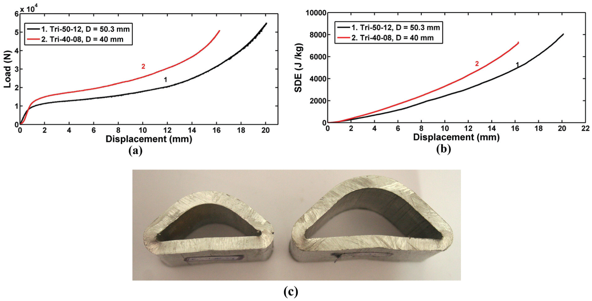
Diagrams of the specimens Tri-40-08 and Tri-50-12 with die apex angle of 90°: (a) load-displacement, (b) specific dissipated energy-displacement and (c) their deformation modes.
Figure 13(c) compares deformation modes of the two specimens with different diameters after the manufacturing process. The specimens Tri-40-08 and Tri-50-12 have the same wall thickness and length. According to the figure, apex angles of both the specimens are the same, but, a little deviation is considered in the base of the specimen Tri-50-12 with the larger diameter. Therefore, the experimental observations suggest using the empty circular tubes with a limited diameter in the introduced forming process or shaping the tubes with the large diameter in the Teflon-filled condition.
Filled tubes with the same filler wall thickness
To investigate the effects of tube diameter on the forming process of the circular tubes into the triangular columns by the cold metal forming, some circular tubes with different diameters and with the same other properties were filled by hollow cylindrical polyethylene Teflon with the same Teflon wall thickness. For this purpose, the specimens Tri-40-9 and Tri-50-13 were prepared with the outer diameters of 40 and 50.3 mm, respectively. Teflon wall thickness of the mentioned specimens is the same and equal to 4.6 mm. Specimens Tri-40-09 with the smaller diameter requires higher lateral load, comparing with the specimen Tri-50-13 with the same Teflon-filler thickness. The results show that load ratio of two specimens in the same lateral displacements of 5, 10 and 15 mm are 1.24, 1.5 and 2.17, respectively. The results indicate that the total dissipated energies by the specimens Tri-40-9 and Tri-50-13 during the forming process are 1429.95 and 1347.62 J, respectively. Also, the SDEs by two mentioned specimens are respectively equal to 19,810.88 and 12,960.38 J/kg. The experiments show that the specimen Tri-40-09 with the less outer diameter has higher lateral load, total dissipated energy and SDE, in comparison with the specimen Tri-50-13 with the larger outer diameter. On the other hand, during the shaping process of the circular tubes into the triangular columns by the cold metal forming process, the tube with the smaller diameter needs higher energy.
Figure 14 demonstrates deformation modes of the specimens Tri-40-9 and Tri-50-13 with different initial diameters and with the same Teflon wall thickness and other characteristics after the cold metal forming process. According to Figure 14, it is found that the specimen Tri-40-9 with the smaller diameter has a straight base, but, an undesirable curvature is considered in the base of the specimen Tri-50-13 with the larger diameter. In other words, in the same Teflon-filled condition, a better forming process is obtained on the tubes with the smaller diameter and to obtain the desirable form in the metal tubes with the large diameter, the thicker cylindrical Teflon-filler must be used, in comparison with the tubes with the same tube wall thickness and the smaller diameter.
Deformation modes of the specimens Tri-40-9 and Tri-50-13 with the die apex angle of 90°.
Filled tubes with the same D′/t′ ratio
In this part, two aluminum tubes with the different tube outer diameters of 50.3 and 40.0 mm and with the same other dimensions were filled by the cylindrical Teflon with the same D′/t′ ratio where D′ is outer diameter of Teflon-filler and t′ is Teflon wall thickness. Figure 15(a) illustrates the curves of SDE versus the lateral displacement of the specimens Tri-40-10 and Tri-50-13 with outer diameters of the Teflon-filler equal to 29 and 39.1 mm and with the Teflon wall thicknesses of 3.4 and 4.6 mm, respectively. The experiments show that both of the total dissipated energy and the ultimate SDE of the specimen Tri-50-13 is more than the specimen Tri-40-10. Besides, total dissipated energy by the sample with the outer diameter of 40 mm is about 758.3 J and the corresponding value of the specimens with the outer diameter of 50 mm is 1347.6 J. It means that in the filled tubes by the same D′/t′ ratio, when the tube diameter increases, the SDE increases.
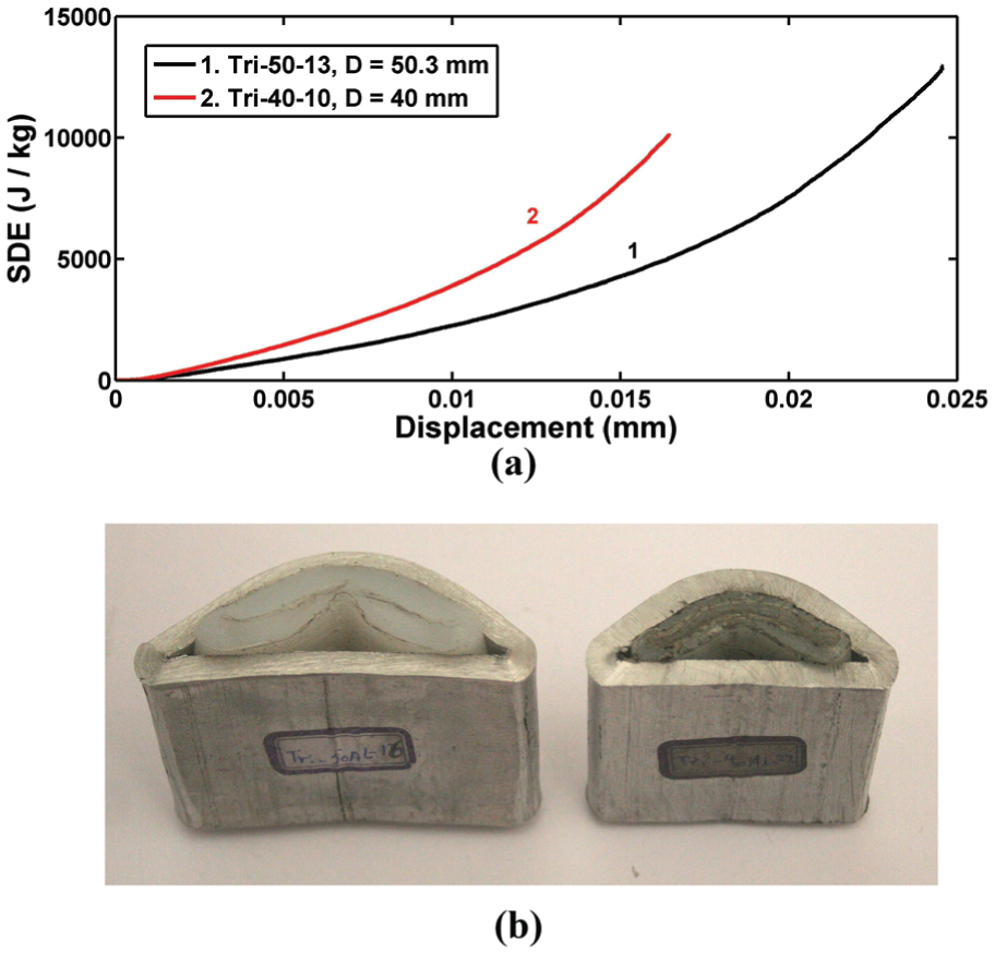
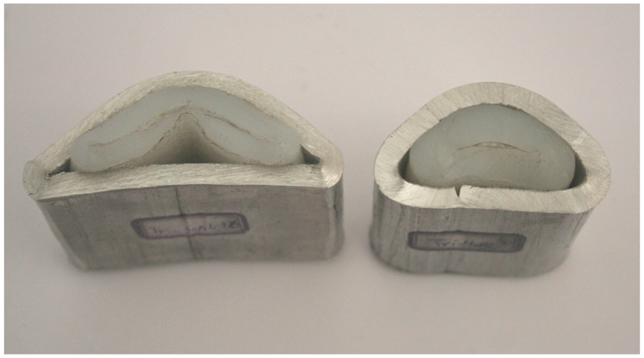
(a) SDE-displacement diagram and (b) deformation modes of the specimens Tri-40-10 and Tri-50-13 with die apex angle of 90°.
Figure 15(b) indicates the manufactured triangular columns after the shaping process on the filled circular specimens Tri-40-10 and Tri-50-13 with the same tube wall thickness and length and with the Teflon-filler of same ratio of D′/t′. On the other hand, a cylindrical Teflon-filler with the thicker wall was used in the tube with the larger diameter. The measurements show that TDs of two filled samples with the different tube diameters and with the same D′/t′ ratio of filler are the same, approximately. Therefore, to obtain the desirable form of the triangular section, by enhancing the tube initial diameter, the cylindrical Teflon-filler with the thicker wall must be used.
Filled tubes with the same filler mass
As the third criterion for investigating influences of the tube diameter on the forming process of the Teflon-filled tubes, rounded specimens Tri-50-13 and Tri-40-11 were filled by the same filler mass and compressed in a V-shape die with the apex angle of 90° to shape them into the triangular sections. Figure 16 represents final shape of the specimens Tri-40-11 and Tri-50-13 with the different initial diameters and with the same Teflon-filler mass. According to criterion of the same filler mass, by decreasing the tube initial diameter, Teflon-filler wall thickness increases. Figure 16 shows that the fracture occurs in the base of the specimen Tri-40-11 with the smaller initial diameter and the thicker Teflon wall. It means that by increasing the Teflon-filler wall thickness, deviation from the desirable form may increases or decreases. On the other hand, for a certain circular tube with a certain initial diameter and tube wall thickness, there is an optimum value for the cylindrical Teflon-filler wall thickness and filling the tubes by the optimum filler causes the best final shape of triangular section.
Deformation modes of the specimens Tri-40-11 and Tri-50-13 with die angle of 90°.
Effects of die angle
Experimental diagrams of the lateral load-displacement and SDE-displacement of three empty aluminum tubes with the same outer diameter of 21.8 mm, wall thickness of 1.6 mm and nominal length of 40 mm are sketched in Figure 17(a) and (b). The similar samples were used in the shaping process on rigid dies with different apex angles of 70°, 90° and 100°, respectively. The figure shows that by decreasing the die apex angle, the ultimate lateral displacement decreases and therefore, the forming process occurs in a shorter time; but, the required load for the shaping process increases and it is due to the smaller bending moment arm around the plastic hinge lines. Also, the results show that the total dissipated energies by the specimens Tri-21-30, Tri-21-31 and Tri-21-32 with the die apex angles of 100°, 90° and 70° are equal to 26.8, 29.2 and 28.4 J and their SDE are 2233, 2524 and 2419 J/kg, respectively. It means that in viewpoint of value of the required forming energy, there is an optimum value for the die apex angle and the shaping process on the die with the optimum angle needs the less SDE.
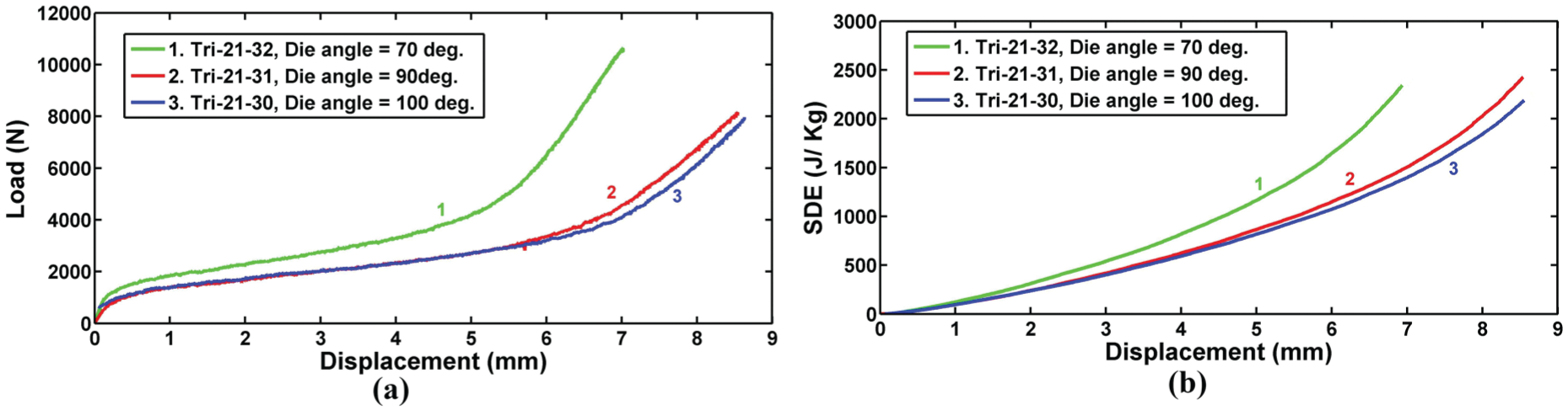
Diagrams of the forming process of the same empty samples on the dies with different apex angles: (a) load-displacement and (b) SDE-displacement.
An experimental comparison was performed between the SDE-displacement curves of the specimens Tri-35-17, Tri-35-18 and Tri-35-19 with the same tube outer diameter of 35 mm, tube wall thickness of 1.9 mm and nominal length of 40 mm and with the same cylindrical filler wall thickness of 4.5 mm. The mentioned samples were compressed during the elastoforming process on the rigid dies with the apex angles of 100°, 90° and 70°, respectively. The ultimate SDEs by the samples Tri-35-17, Tri-35-18 and Tri-35-19 are 2324, 2338 and 1377 J/kg, respectively. Therefore, in the studied cases of the filled specimens, the sample with the less die apex angle has the least SDE. Figure 18 illustrates the final shape of the specimens Tri-35-17, Tri-35-18 and Tri-35-19 with the same tube characteristics and filling condition but with different die apex angles of 100°, 90° and 70°, respectively. The experimental observations show that deviation parameter of Δ1 of the samples with the die apex angle of 100°, 90° and 70° are respectively equal to 0.05, 0 and 0 mm. Therefore, by decreasing the die angle, the final shape of triangular section base inclines to a straight line. However, by filling the tubes by an optimum filler wall thickness, the straight shape of the base can be controlled. Also, the results show that deviation parameter Δα for all the studied die angles of the mentioned samples are the same and equal to −1, and so, it is found that deviation of the triangular section apex angle is independent of the die angle, in the studied cases. Furthermore, the measurements indicate that r1 of the samples with the die apex angles of 100°, 90° and 70° are 1.2, 1.6 and 3.1 mm, respectively. Thus, by increasing the die angle, curvature radius of the produced column decreases and it is a desirable phenomenon. Totally, TDs of the specimens with the die angles of 100°, 90° and 70° are obtained as 3.25, 4.2 and 7.2, respectively, and it means that in the shaping process of the circular tubes into the triangular columns, controllability of deformation mode of the produced samples increase, by increasing the die apex angle.
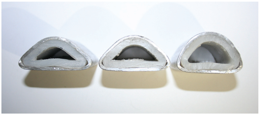
The final shapes of the specimens Tri-35-17, Tri-35-18 and Tri-35-19 with different die apex angles of 100°, 90° and 70° and with the same other characteristics.
Theoretical analysis validation
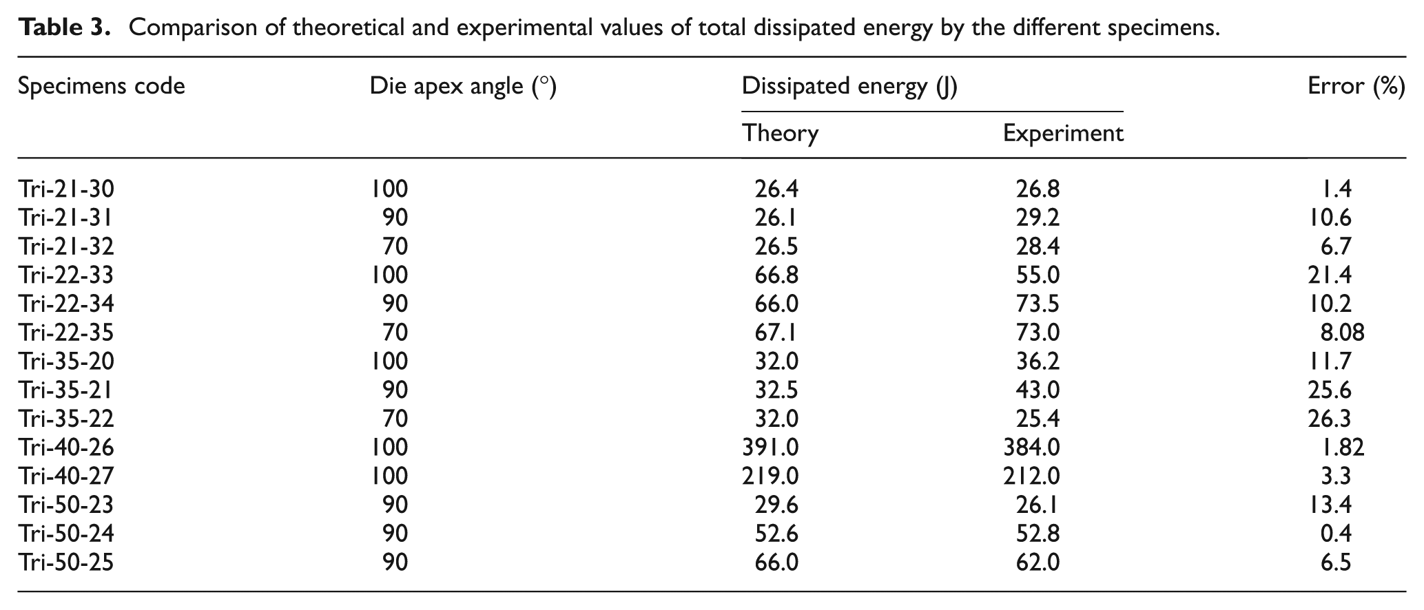
In this work, a new theoretical model of deformation was introduced and two new theoretical relations were derived to estimate total dissipated energy during the shaping process of empty and Teflon-filled circular tubes into the triangular columns. To investigate verity of the introduced theory, the total dissipated energy during the forming process of the empty specimens that was measured by the testing machine is compared with the theoretical predictions by equation (8). The mentioned relation estimates the total dissipated energy of the shaping process versus length, mean radius and wall thickness of initial tubes and also, flow stress of tube material and die apex angle. Table 3 compares the theoretical estimations by equation (8) and the corresponding experimental measurements of the total dissipated energy during the shaping process of the empty circular tubes into the triangular sections. Comparison of the results show that the theoretical formula estimates the total dissipated energy by the empty tubes with a reasonable agreement and it shows precision of this theory.
Comparison of theoretical and experimental values of total dissipated energy by the different specimens.
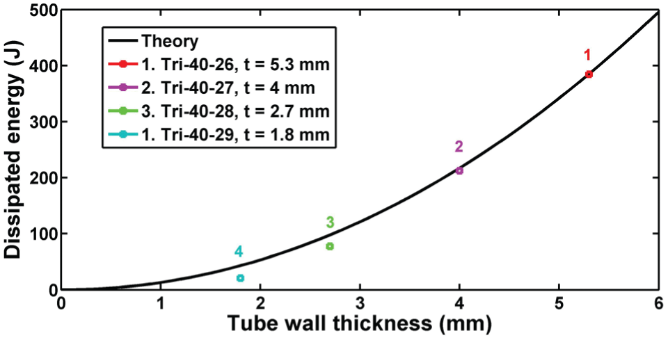
Reviewing of the theoretical equation (8) shows that total dissipated energy during the forming process is dependent on flow stress of tube material, linearly. Also, the mentioned relation indicates that total required energy for shaping the circular tubes into the triangular columns is dependent on tube wall thickness, nonlinearly. For the better conclusion, Figure 19 illustrates theoretical curve of total dissipated energy versus to tube wall thickness. Also, Figure 19 shows some points corresponding to the experimental results of the performed forming test on the empty tubes with different wall thicknesses and with the same other properties. The figure shows that both of the theoretical analysis and the experimental results have the same trend. On the other hand, theoretical equation (8) shows a nonlinear increment in total dissipated energy versus tube wall thickness and the similar trend is considered in the corresponding experimental points. Both of the results indicate that total required energy for forming the empty tubes between a V-shape die and a flat punch is dependent on tube wall thickness such as a second order polynomial function. Also, equation (8) indicates that total dissipated energy during the shaping process is dependent on die apex angle. Figure 20 shows the theoretical curve of total dissipated energy by empty samples versus die apex angle. Furthermore, the experimental results of the forming process on the empty circular tubes with the same tube characteristics that were compressed on the rigid dies with different die apex angles are illustrated as the points in Figure 20. The figure shows an acceptable correlation between the results. The theoretical curves show that when the die apex angle increases, the total dissipated energy decreases, smoothly. For better comparison, equation (8) is rewritten as the following relation
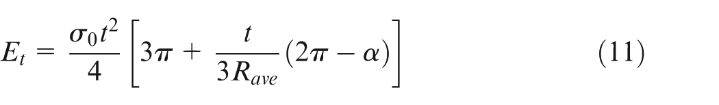
Comparison of the theoretical and experimental results of total dissipated energy variations versus tube wall thickness.
Comparison of the theoretical and experimental results of total dissipated energy variations versus die apex angle.
Recent relation shows that die apex angle α has a coefficient of t/(3Rave) and the introduced method of deformation can be used for the tubes with small ratio of t/Rave. Therefore, according to the theoretical equation (11), it is found that variations of die apex angle have a little effect on total dissipated energy by the empty tubes during the forming process. Figure 20 shows the same results based on the experiments. As a numeric study, the experimental results show that die apex angle of the specimen Tri-21-30 is 42.8% larger than the corresponding value of the specimen.
Tri-21-32, but, total dissipated energies by the mentioned samples are respectively equal to 26.8 and 28.4 J that shows a difference less than 6%.
Also, in the theoretical part of this research work, equation (10) has been derived to estimate total required energy for shaping the circular tubes into triangular sections, in the Teflon-filled condition. Plateau stress of the used polyethylene Teflon-filler is equal to 22 MPa. As a numeric comparison, total forming energy of the filled specimen Tri-35-17 with tube outer diameter of 35 mm and die apex angle of 100° is obtained as 80.1 J according to the experimental test, and the corresponding value of the theoretical prediction by equation (10) is calculated equal to 81.5 J that shows an error percentage of 1.75%. Furthermore, experimental and theoretical values of forming energy by the filled specimen Tri-35-18 with tube outer diameter of 35 mm and die apex angle of 90° are 78.7 and 81.2 J, respectively. The reported results show that a difference of 3.2%. As the next example, experimental forming energy and the corresponding theoretical value of the filled tube Tri-30-06 with outer diameter of 29.5 mm and filler wall thickness of 3.2 mm are respectively equal to 31.3 and 28.8 J that illustrates an error of 8%. In addition, error percentages of analytical estimations by equation (10) for the filled specimens Tri-30-07, Tri-30-03, Tri-30-02 and Tri-30-01 are equal to 10.3%, 12.2%, 14.8% and 19.9%, respectively, with respect to the corresponding experiments. The performed comparisons show that the theoretical formula (10) can predict total required energy for shaping circular metal tubes into triangular sections in the Teflon-filled condition with the acceptable correlation and it asserts precision and verity of this theory. However, error percentages of some specimens with thick-walled cylinder of Teflon-filler are considerable. For example, error of theoretical predictions by equation (10) for the specimen Tri-30-04 with tube outer diameter of 29.5 mm and Teflon-filler wall thickness of 9.2 mm is 55.35%. The large value of error percentage of the recent specimen is due to using the thick-walled filler into the tube during the shaping process. During the forming process on filled circular tubes with thick-walled filler, after a certain displacement, the hollow cylindrical Teflon-filler transforms into a solid geometry and then, a considerable resistance occurs by the filler against the punch movement and it increases total forming energy and consequently, error percentage respect to the theoretical estimations.
In this theory, some analytical relations were derived to predict dissipated energy during the forming process of triangle tubes, for the first time. For this purpose, a theoretical deformation model was introduced for the shaping process of empty circular tubes into the triangular specimens. Two plastic hinge lines were considered in the theoretical model. Experimental results show that almost in all the cases, curvature radius of circular tubes intensively increases during the forming process. As numeric investigations, curvature radiuses of two corners of the empty specimen Tri-35-20 are 2.0 and 2.3 mm, while, curvature radius of the initial circular tube was 17.5 mm. It means that curvature radiuses of two corners of the formed triangular column are 0.11–0.13 times of curvature radius of the initial simple tube. It shows that considering two corners of the formed triangular tube as the sharp corner is almost compatible with deformation mode of the specimens and does not make a considerable error. Also, numeric comparisons of total dissipated energy during the forming process of all the empty samples show that error percentage of theoretical predictions varies between 0.4% and 26.3%. On the other hand, theoretical predictions of forming energy of more than 78% of all the specimens are less than 14%. It affirms verity of the theoretical deformation model and the derived analytical relations.
Conclusion
This work introduces a new cold metal forming process for shaping the circular metal tubes into the triangular columns, using a flat punch and a V-shape die. For this purpose, some specimens were prepared and laterally compressed. In each test, deformation mode, lateral load, dissipated energy and SDE of the sample are studied. The experimental results show that using the cylindrical Teflon-filler, deformation mode of the triangular tubes improves, significantly. Also, investigation of the deformation modes of the empty and polyethylene Teflon-filled specimens illustrates that there is an optimum value for wall thickness of cylindrical Teflon-filler and filled tubes with the optimum Teflon has the best deformation mode. The experiments indicate that the best deformation mode occurs in tubes with the Teflon wall thickness of 10%–15% of the tube inner diameter. The experimental results show that by increasing the specimen outer diameter, thicker cylindrical Teflon-filler is required to achieve the desirable triangular section. According to the results, by increasing the tube wall thickness, probability of crack initiation and fracture reduces. The experimental measurements show that lateral load and dissipated energy by the tubes are proportional to the tube initial length; however, deformation mode is independent of the tube length. Furthermore, this study presents a new theory for predicting the dissipated energy during the shaping process of circular metal tubes into the triangular columns in two different conditions of empty and polyethylene Teflon-filled. The theoretical and experimental results showed a good agreement.
Metal tubes with triangular cross-section can be produced by different methods such as hydroforming and extrusion. This work suggests elastoforming or cold forming using an elastomer as the filler. Results of the previous published works15,16 that investigated production of multi-corner columns by the hydroforming method show that a hydraulic system with high oil pressure and some expensive dies are required to shape the columns and it means that multi-corner columns are produced by a very expensive forming process. Also, in the hydroforming process, when a multi-corner tube with large length is required, an initial circular tube with large length is used, and therefore, high volume of pressurized oil and an oil tank with high capacity is needed. In the introduced method of this research, triangular tubes are produced by compressing the simple circular tubes between a rigid platen and a V-shape die in the Teflon-filled condition. The introduced method is simpler and cheaper, with respect to the hydroforming method.
Footnotes
Acknowledgements
The authors gratefully acknowledge Eng. Ezzatallah Hosseinzadeh for his supports in preparing the specimens and Mr Yashar Abdolzadeh for his helps in this research program. Also, the authors gratefully acknowledge Strength of Materials Laboratory in Yasouj University.
Declaration of conflicting interests
The authors declared no potential conflicts of interest with respect to the research, authorship and/or publication of this article.
Funding
The author(s) received no financial support for the research, authorship and/or publication of this article.