
Abstract
This article introduces a new metal forming process for creating a fold with a controllable and certain wavelength into the circular metal tubes during the axial compression. Also, a new analytical model of plastic deformation of the circular metal tubes constrained between two rigid punches subjected to quasi-static axial loading is introduced. Based on the deformation model, some theoretical relations are derived to predict the instantaneous axial load of a complete fold creation into the tubes versus the axial displacement in the elastic and plastic zones. Four different mechanisms of energy absorption are considered in the present theoretical model: two kinds of bending mechanism around circular hinge lines, circumferential expansion and unbending mechanism corresponding to meridian strain. Theoretical prediction shows that the required axial load for creating a complete fold in a constrained metal tube between two rigid punches is dependent on the tube wall thickness, internal radius and initial free length of the tube and also tube material properties. Also, some quasi-static axial compression tests were performed on the circular tubes of brass and aluminum alloys between two rigid punches, and the results were compared with the theoretical predictions that showed a reasonable agreement. Furthermore, the experimental observations show that wavelength of a complete created fold into the circular tubes could be controlled using two rigid dies during the folding process and using the poly(vinyl chloride) Teflon as the filler, instead of the intrinsic wavelength of the tube.
Keywords
Introduction
Metallic alloy devices with the ability of irreversibly kinematics energy absorption under impact conditions have many important engineering safety applications including crashworthiness and blast resistance. 1 Thin-walled tubular structures are the most common elements used as crash protection systems that convert kinetic energy into irreversible plastic deformation energy in moving parts. 2 There are many types of energy absorption systems such as axial folding, splitting process, expansion mechanism, tube inversion and flattening processes under the different loading conditions. An energy-absorbing system may consist of a tube or system of tubes that are compressed axially, which absorbs the kinetic energy upon impact and hence dissipating it as plastic work. 3
Kim et al. 4 investigated the compressive deformation behavior under dynamic loading to evaluate impact energy absorption by extruded aluminum tubes for space frame design, experimentally. Singace 5 examined the collapse of tubes in the multi-lobe in an attempt to evaluate the crushing load. The analysis produced a distinctive value for the eccentricity factor that simplifies the expression for the mean collapse load, which is a function of tube geometry and number of lobes. Hanssen et al. 6 carried out an experimental program to study the axial deformation behavior of triggered, circular AA6060 aluminum extrusions filled with aluminum foam under both quasi-static and dynamic loading conditions. Gupta and Abbas 7 presented a mathematical analysis for axial crushing of round tubes in concertina mode, wherein the change in thickness along the fold length during its formation and the difference in the yield stress values in compression and tension were incorporated.
Mahdi et al. 8 concentrated on the effects of hybridization on the crushing behavior, energy absorption and also failure mechanism and mode for composite cylinders. They investigated the static crushing behavior of filament wound laminated circular–cylindrical composite shell under uniform axial load, experimentally. Abbas et al. 9 developed a plastic curved fold model with partly inside and partly outside folding and variable straight length. They determined size of fold and proportions of inside and outside fold lengths by minimizing the average crushing load. Their validation with experiments provided reasonably good agreement. Gupta et al. 10 reconsidered a straight fold model for the analysis of the tubes under axial compression. Nagel and Thambiratnam 11 compared the energy absorption response of straight and tapered thin-walled rectangular tubes under quasi-static axial loading, for variations in their wall thickness, taper angle and number of tapered sides. Abdul-Latif et al. 12 controlled the plastic flow mechanism during axial collapse of metallic hollow cylinders for the absorbed energy. They presented an experimental methodology and for this purpose, some different tubular structures were loaded under compressive quasi-static strain rate.
Gupta and Venkatesh 13 conducted axial compression experiments on aluminum cylindrical shells on a gravity drop hammer setup. Also, they presented typical histories of their deformation, variation in shell thickness along the fold length, inner and outer radii, folding parameter and size of fold, load–compression curves, energy-absorbing capacity, initial peak load and mean collapse load. Gameiro and Cirne 14 analyzed energy absorption behavior of thin aluminum tubes filled with agglomerate cork subjected to un-axial impact loading. Also, they carried out numerical simulations that globally showed good agreement with the experimental results. Chai 15 studied energy absorption and load-bearing capacity of single and concentric multilayer tubes under axial compression with an eye toward optimization per structural mass or volume available for deformation. Ahmad and Thambiratnam 16 studied axial crushing and energy absorption response of foam-filled conical tubes under quasi-static axial loading, using nonlinear finite element models. Chen and Ozaki 17 studied the nonlinear elasto-plastic behavior of circular tubes with corrugated surfaces that were subjected to axial compression using the finite element method. Zhang and Yu 18 performed a study of axial crushing of pressurized thin-walled circular tubes to investigate the effect of internal pressure on energy absorption of thin-walled structures. Also, in the experiments, they axially compressed three groups of circular tubes with different radius/thickness ratios under different pressurizing conditions.
Zhang et al. 19 presented a study of the effectiveness of adding a buckling initiator that is used to reduce the initial peak force of a thin-walled circular tube under axial impact loadings. The buckling initiator was installed near the impact end of the circular tube and was composed of a pre-hit column along the axis of the tube and several pulling strips uniformly distributed around the top edge of the tube. Salehghaffari et al. 20 experimentally studied two new structural design solutions with the aim of improving crashworthiness characteristics of cylindrical metal tubes. Niknejad et al. 21 derived a theoretical formula to predict the instantaneous folding force of the first fold creation in a single-cell hexagonal honeycomb under axial loading. Fyllingen et al. 22 studied influence of element type and formulation in finite element analyses of aluminum profiles subjected to axial crushing. Niknejad et al. 23 presented a theoretical formula to predict the instantaneous folding force of a polyurethane foam-filled square column as a single unit of square honeycombs under the axial loading. Zhang et al. 24 presented a new type of honeycomb sandwich circular column that is a composite structure composed of two circular aluminum tubes filled with core shaped as a large-cell honeycomb lattice. Also, comparisons of the interaction effect between tubes and filler, the deformation modes and the energy absorption abilities of these columns were conducted. Tarlochan and Ramesh 25 carried out a comprehensive experimental investigation on the response of composite sandwich structures to quasi-static compression. They studied crashworthiness parameters of various types of composite sandwich structures in a series of edgewise axial compression tests. Niknejad et al. 26 derived some theoretical relations to predict the mean folding force, total absorbed energy per unit of tube length and specific absorbed energy per unit of total mass by the polyurethane foam-filled grooved tubes with circular cross section under the axial compression process.
This article introduces a new cold metal forming method to produce a complete fold in the circular metal tubes with a certain folding wavelength. A theoretical model of plastic deformation in the circular tubes constrained between two rigid punches under the quasi-static axial load is introduced, and based on the present model, a theoretical relation is derived to estimate the instantaneous required axial load for creating a complete fold in the circular metal tubes with a controllable wavelength. Reviewing the previous published works23,27 reveals that during the folding process on a circular metal tube with certain material and geometry, the folds are created with a wavelength that is dependent on the tube geometry and so, it is an intrinsic parameter of the tube and is not controllable. Controllability of the folding wavelength during the process is the main advantage of the present method of cold metal forming and to achieve the purpose, poly(vinyl chloride) (PVC) Teflon fillers are used as the filler into constrained tubes between two special punches. Based on the present forming method, for forming a fold in circular tube with the wavelength less than intrinsic value, initial free length of empty constrained specimen is selected less than intrinsic wavelength and so, one fold with desirable wavelength is created in the sample. Also, to form a fold with the wavelength longer than intrinsic value, initial free length of constrained tube is selected longer than intrinsic wavelength and the tube is filled by the PVC Teflon filler.
Theory
An analytical model of deformation is introduced to determine the axial load of the constrained circular metal tube between two rigid punches during the folding process. The theoretical analysis is performed based on the energy method to derive the analytical equations. In the theoretical analysis, circular tubes are assumed as a rigid-perfectly plastic material with flow stress of σ 0 that is estimated as the following relation 27
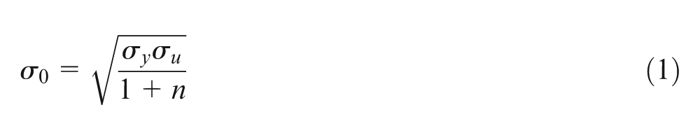
where n indicates strain hardening exponent of tube material, and also σy and σu are yield stress and ultimate stress, respectively. Figure 1 shows a circular tube constrained between two punches, before and during the axial deformation. According to Figure 1(b), when the axial load is applied on two upper and lower punches, three plastic hinge lines are created in the circular tube. As shown in Figure 1, during the process, plastic deformations of a constrained tube are symmetric and three plastic hinge lines such as circles are created in tube wall (points A–C). Rotation of points A–C around the central axis of circular tube shows three circular plastic hinge lines. Generally, energy absorption rate due to the bending process around a straight hinge lines with the initial length of C is calculated as
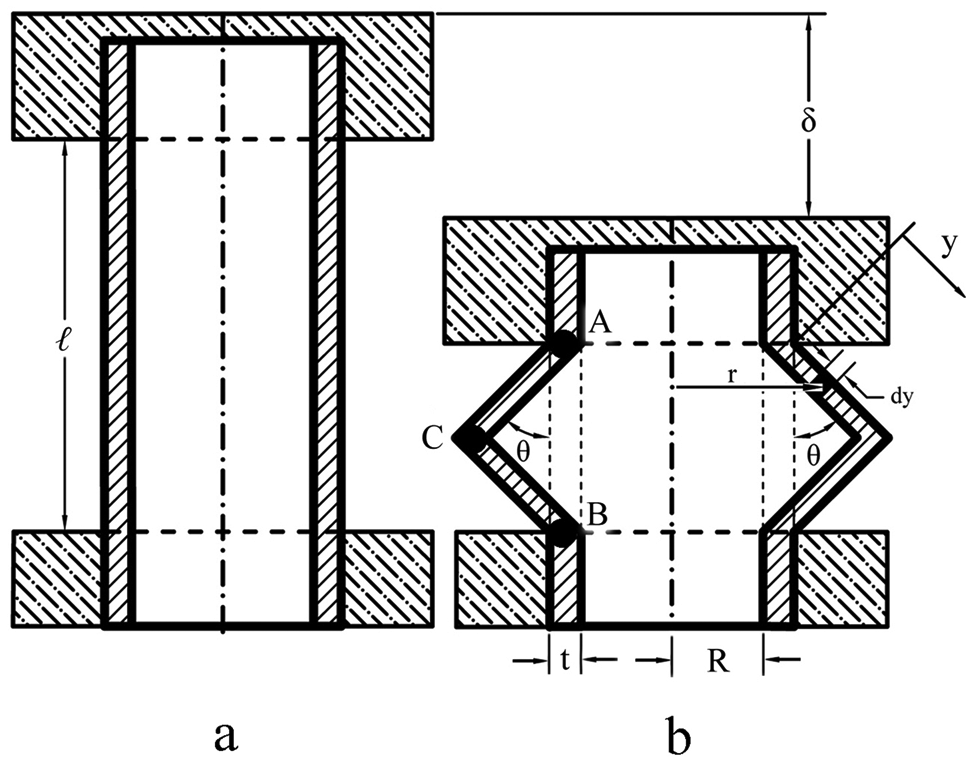
New theoretical deformation model of the constrained circular tube during the cold metal forming process. a) before deformation, b) during the plastic deformation
In the above equation, α is a finite rotation around the hinge line. M 0 is fully plastic bending moment per unit of length and is obtained as
where t indicates tube wall thickness. According to Figure 1(b), in the present model, deformation of the tube is symmetric. Therefore, absorbed energy by two hinge lines of A and B are equal. According to Figure 1, instantaneous finite rotation around the hinge lines A and B are the same and equal to θ. Also, length of each mentioned hinge line is equal to average circumference of the tube and is equal to C = π(2R + t). Therefore, absorbed energy rate by the hinge line A or B is obtained as
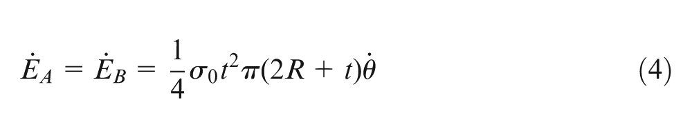
where R is the initial internal radius of the circular tube.
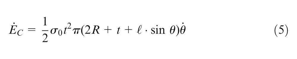
As shown in Figure 1(b), there is the plastic hinge line C in the tube. According to the figure, the initial angle between the edges of AC and CB is equal to π − 2θ. Therefore, finite rotation around the plastic hinge line C is equal to 2θ. By substituting the value of
where
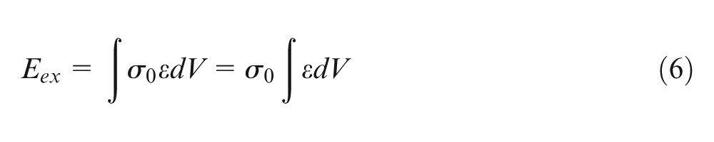
In the above relation, dV is the volume element of the tube wall and dV = πt(2R + t)dy, where y varies between 0 and
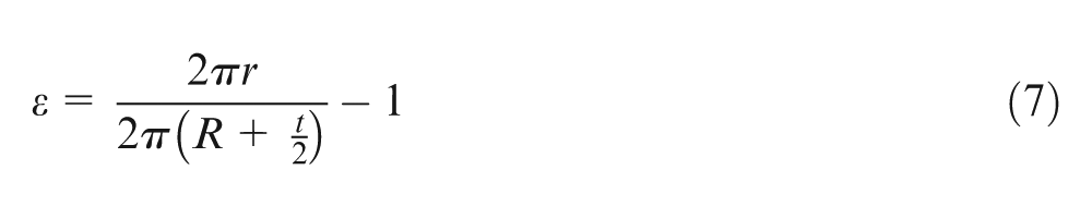
where r is the instantaneous radius of the volume element and is equal to
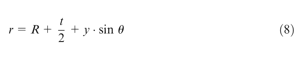
Substituting equation (8) in equation (7) results in the following relation for calculating the circumferential strain of the volume element
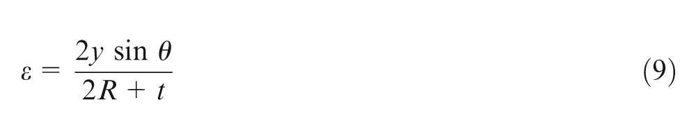
Therefore, the absorbed energy during the expansion process in the circular tube is estimated as
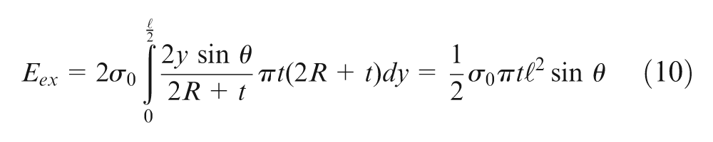
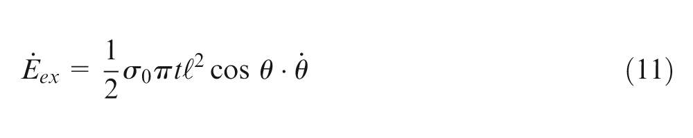
Rate of the absorbed energy by the expansion deformation in the constrained tube is derived as follows
At the onset of axial displacement, the tube wall has the initial curvature radius of R + t/2. During the plastic deformation, the initial curvature of the free part of the tube with the initial length of
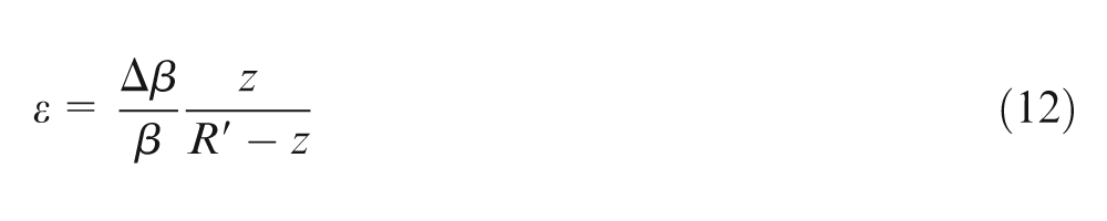
In the above relation, β is the central angle of each assumed curved beam, R′ is the neutral axis radius and is obtained as R′ = t/ln(1 + t/R). Also, z is the radial distance to the neutral axis. Initial angle of β is equal to π. At the end of deformation process, each assumed curved beam transforms to a straight beam. Therefore, central angle of each assumed curved beam after the wall flattening is equal to β = 0. Considering variations in angle β linearly versus the axial displacement as
where δ indicates instantaneous axial displacement and by considering the geometry of the present theoretical deformation model for constrained tube according to Figure 1, it is obtained as follows
Therefore, rate of axial displacement versus rate of the folding angle
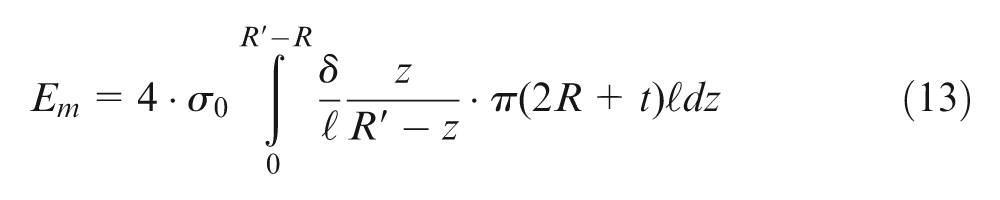
Absorbed energy due to the tube wall flattening process is calculated as
where k is equal to
Rate of the absorbed energy due to the tube wall flattening process is obtained as follows
The theoretical deformation model shows that all the material volume of the free part of the tube with the initial length of
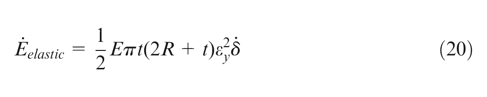
In the above equation, εy indicates the yield strain and E shows the modulus of elasticity. According to the previous relation, the rate of the elastic energy absorption by the constrained tubes is obtained as follows
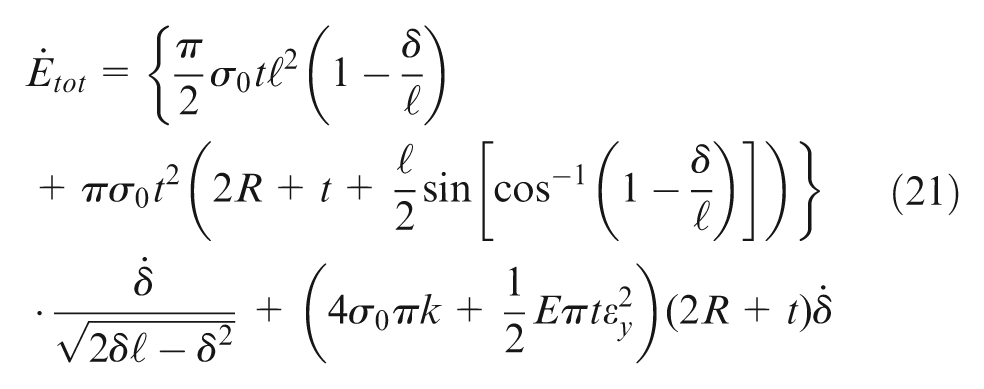
The summation of the dissipated energy rates during the process results in the following relation to predict the rate of the total absorbed energy by the constrained circular metal tube between two rigid punches under the axial loading during a fold creation
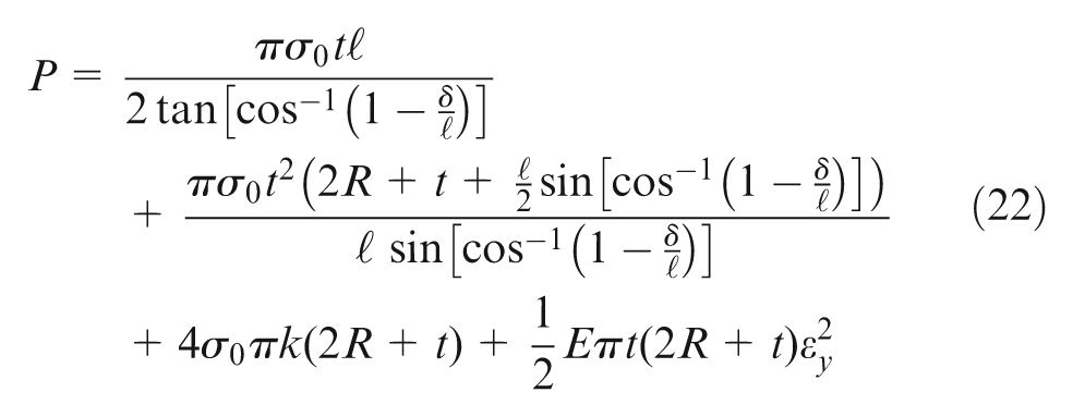
Therefore, the instantaneous axial load during a fold creation in the circular tube with a certain folding wavelength is derived as
Experiment
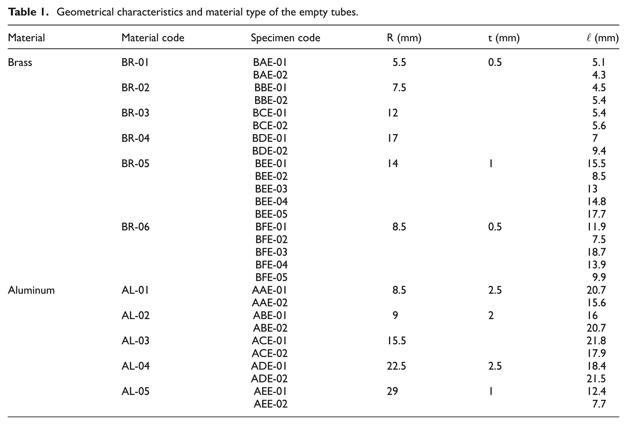
The quasi-static axial compression tests were carried out on circular tubes, and diagram of the axial force versus the axial displacement was sketched for each specimen. Some tubes were made of brass and the others were made of aluminum. Circular tubes with the different inner diameters and various wall thicknesses were machined to the required lengths. Geometrical characteristics of the constrained tubes are given in Table 1. For each circular tube, two pieces of a hardened steel shaft were machined to the required size and then were drilled to make the rigid upper and lower punches, as shown in Figure 1(a). Internal radius of the punches and external diameter of the corresponding tube were selected as the clearance fit. The rigid cylindrical punches were used as the rigid supports on both the sides of the metal tube, to prevent plastic deformation in two ends of the specimens and control the forming process. Length of each circular tube was chosen such that just one fold happens in the free length of the constrained circular tubes.
Geometrical characteristics and material type of the empty tubes.
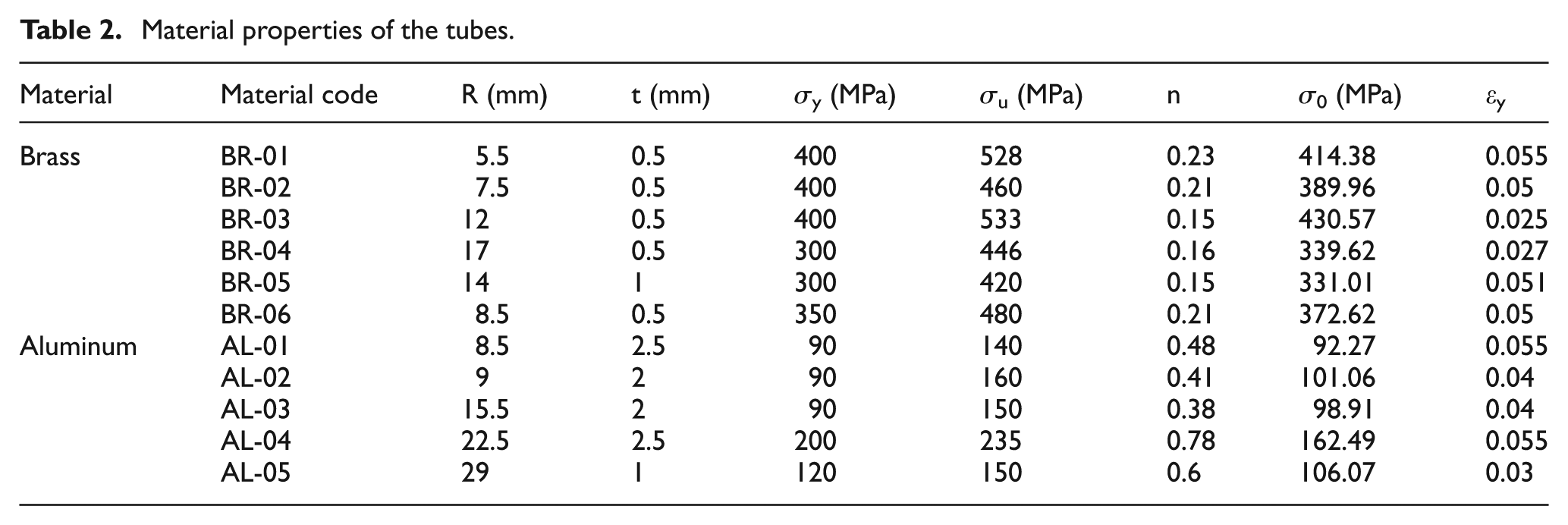
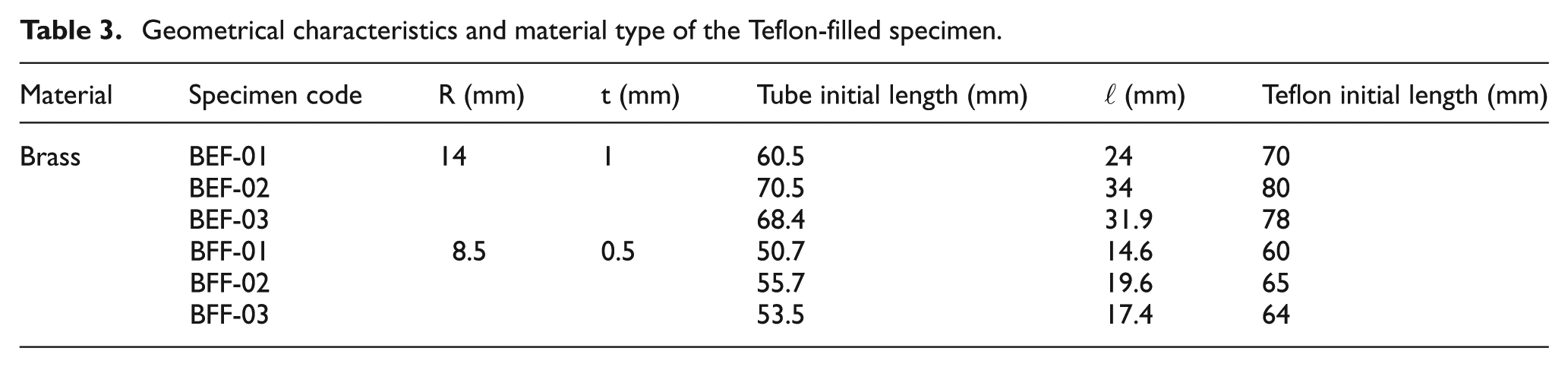
All the tests were performed by a DMG machine, model 7166. The circular tube and punches were placed between two rigid plates to perform axial compression tests. All the experimental tests were carried out under the quasi-static condition. To obtain material properties of the tubes, a dumbbell shape specimen of each tube material was prepared and quasi-static tension test was performed on it, according to the standard ASTM E8M. Table 2 gives material properties of each tube. Moreover, some solid cylinders of PVC Teflon were prepared and used into the corresponding tubes as the filler and experimental tests were performed on the PVC Teflon-filled samples in order to control the folding wavelength. Geometrical characteristics of the PVC Teflon-filled specimens are shown in Table 3. In all the filled specimens, initial length of the Teflon filler was selected approximately 10 mm larger than the initial length of the corresponding circular tube.
Material properties of the tubes.
Geometrical characteristics and material type of the Teflon-filled specimen.
Totally, circular brazen tubes with six different alloys and diameters were prepared. In four brazen alloys, the tubes were compressed with two different initial free lengths, and in two other brazen alloys, the samples were tested with five different initial lengths. Furthermore, circular aluminum tubes were prepared with five different aluminum alloys and for each aluminum alloy, the tubes were formed with two different initial lengths. Also, some brazen specimens were used in the forming process with two different diameters and for each diameter, three different initial free lengths were prepared.
Results and discussion
Using the PVC Teflon filler into the circular metal tubes to control the folding wavelength is a new idea that is investigated in this work. For this purpose, a theoretical analysis was introduced to predict the instantaneous axial load versus the axial displacement during a fold forming process in the circular tubes and then some axial compression tests were performed on the tubes in two different conditions: empty and PVC Teflon-filled. The effects of PVC Teflon filler and tube dimensions are investigated as follows.
Prediction of maximum axial load
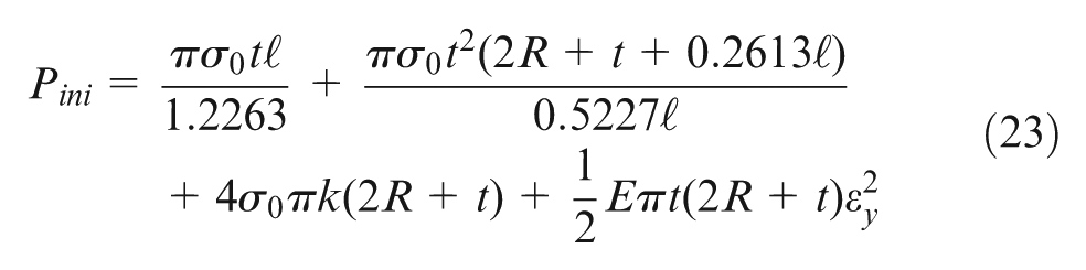
During the theoretical analysis based on the introduced model of deformation, plastic deformation was only considered and elastic zone was neglected. Also, the theoretical relation for predicting the axial force does not give a certain value for the maximum axial load during the process. In this part, a semi-empirical relation is obtained to estimate the maximum axial load and to estimate the elastic part of the load–displacement diagram of a constrained metal tube between two rigid punches, during a complete fold creation process. The maximum axial load indicates the minimum axial load that is required for forming a fold in a circular tube. Reviewing of the experimental results of this work shows that the maximum value of the axial load during a fold creation process occurs when the fold angle is approximately equal to θ = 31.5°. According to equation (14), axial displacement corresponding to the initial load is equal to
The axial load during the elastic zone varies versus the displacement, linearly. Therefore, the elastic part of the axial load–displacement diagram of a fold creation process in a constrained metal tube between two rigid punches is calculated as the following relation
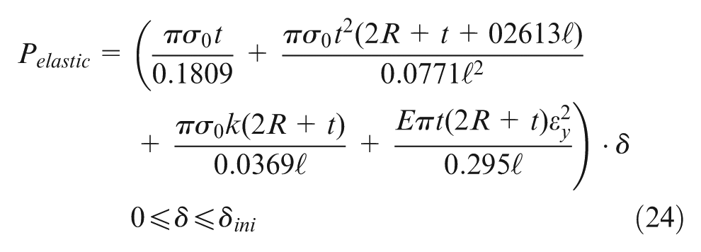
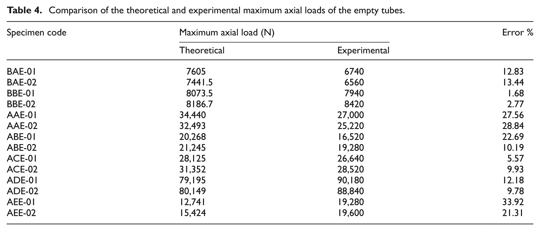
Table 4 compares the theoretical estimation by equation (23) and the corresponding experimental results of some specimens and the error percentages. According to the reported data in Table 4, it is concluded that in more than 78% of the investigated specimens, the error percentage of the theoretical predictions is less than 25%. Comparison of the corresponding results shows that semi-empirical equation (23) estimates the minimum required axial force to form a complete fold into the constrained metal tubes between two rigid punches with the acceptable correlation. When the axial load reaches to the prediction value by equation (23), the fold formation process occurs in the circular metal tubes and it shows importance of equation (23) in application viewpoint.
Comparison of the theoretical and experimental maximum axial loads of the empty tubes.
Verification of the theoretical analysis
The experimental observations show that at commencement of folding, the axial force increases from 0 to its maximum value and then follows a decreasing trend. After a completed folding, the folding force reaches a relative minimum value. Theoretical equation (22) was derived to predict the load–displacement diagram of the process in the plastic deformation zone. Also, semi-empirical equation (24) estimates the elastic part of the load–displacement curve. To validate the present analytical relations, Figure 2 shows the theoretical and experimental graphs of the instantaneous axial load versus the axial displacement of the constrained circular brazen specimen BAE-02. By considering the theoretical diagram and the corresponding experimental curve, it is concluded that theoretical analysis can estimate the instantaneous axial load against the axial displacement with a good correlation. This agreement shows the nicety and accuracy of the theoretical analysis and infers that the considered plastic deformation in the new theoretical deformation model of constrained metal tube between two rigid punches is congruous with the mechanical behavior of the specimen during the fold formation process. Measurements show that slopes of theoretical and experimental diagrams of the specimen BAE-02 at the same displacement of 0.35 mm are equal to 13,200 and 11,730 N/mm and also those at the same displacement of 2.05 mm are equal to −600 and −620 N/mm, respectively. Comparisons show errors of 11.14% and 3.34%, respectively. Good agreement between the slopes of the theoretical and corresponding experimental curves in two different points affirms that the general form of the mathematical function that was derived for predicting the axial load–displacement diagram of the constrained tubes is correct and compatible with the mechanical behavior of the tubes during the elastic and plastic deformations.
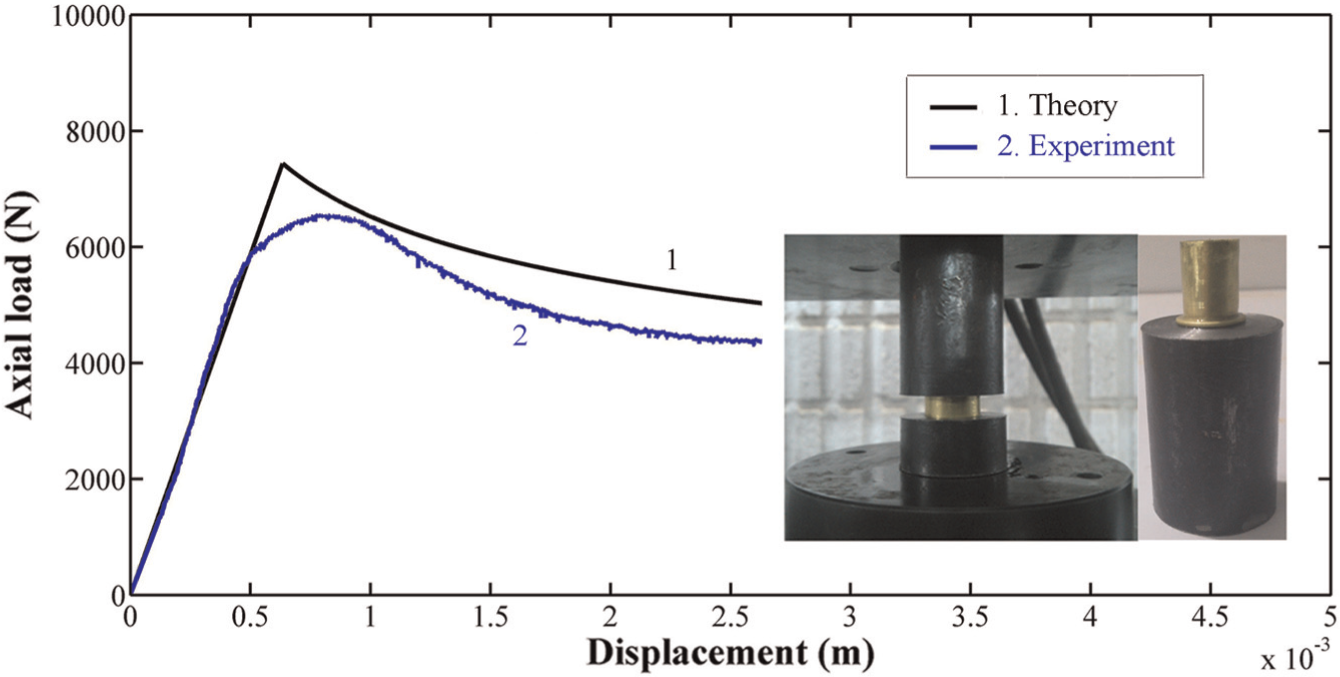
Theoretical and experimental diagrams of the instantaneous axial load–displacement of the specimen BAE-02.
Figure 3 illustrates both the experimental and theoretical diagrams of the axial load–displacement of the specimen ABE-01 made from aluminum alloy. Also, the similar curves for the aluminum specimen ACE-02 are sketched in Figure 4. In both the figures, comparison of two curves shows an admissible correlation and affirms verity of the theoretical analysis. Also, Figures 2–4 show that the present analytical formulas predict the instantaneous axial load versus the axial displacement of the aluminum specimens as well as for the brazen tubes. Furthermore, Figures 2–4 show a logical correlation between the theoretical and experimental results. For example, at the axial displacement of 9 mm, the theoretical and experimental axial loads of the aluminum specimen ACE-02 are 23,720 and 25,520 N, respectively. Therefore, the error percentage of the analytical prediction is less than 7.05%. Also, at the axial displacement of 1.5 mm, theoretical and experimental axial loads of the brazen tube BAE-02 are, respectively, equal to 5841 and 5180 N and the difference is 12.76%.
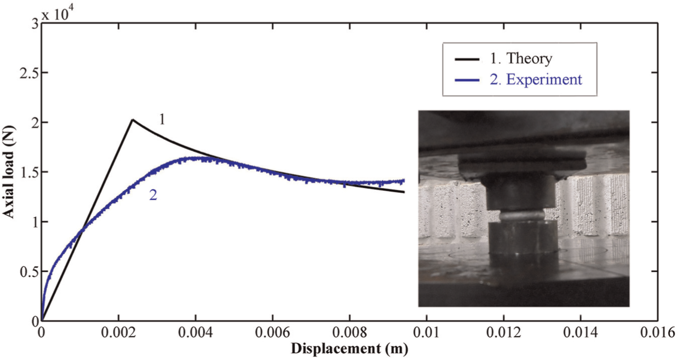
Theoretical and experimental diagrams of the instantaneous axial load–displacement of the specimen ABE-01.
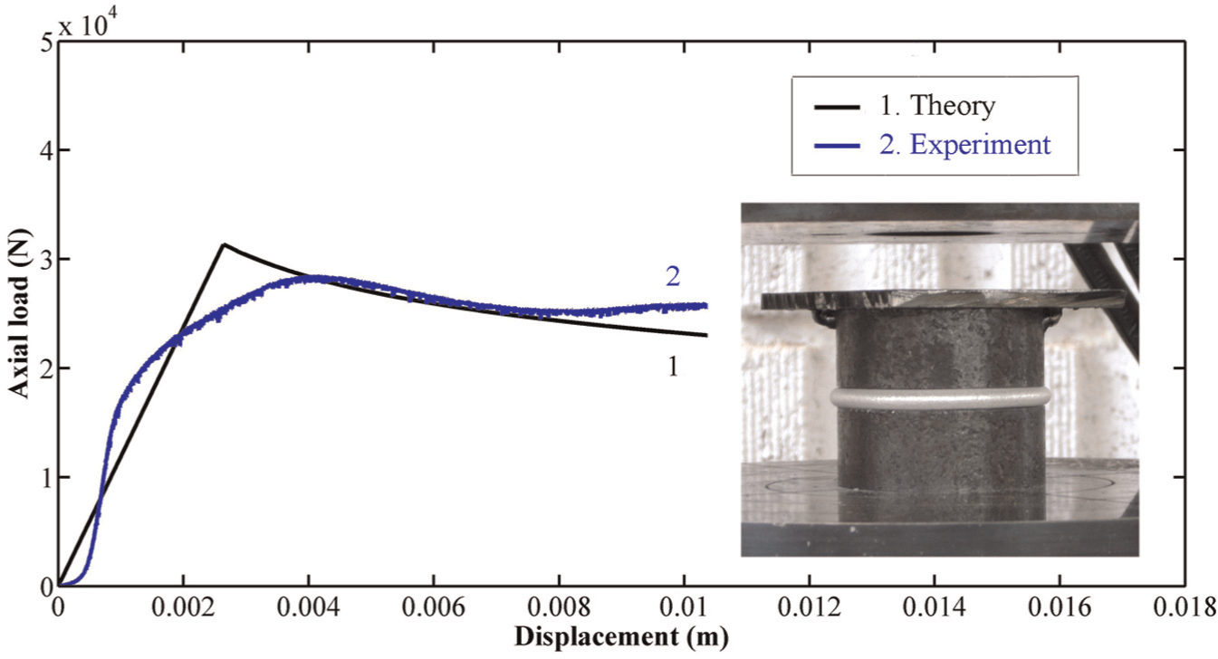
Theoretical and experimental diagrams of the instantaneous axial load–displacement of the specimen ACE-02.
The controlled deformation mechanism that is investigated in this work can be used for different usages, such as manufacturing the exhaust of automobiles and also vibrating damper by creating the several folds in a circular tube.
Effects of tube initial free length
Figure 5 shows the axial load–displacement diagram based on the experimental tests on the brazen specimens BDE-01 and BDE-02. Initial free lengths of two brazen tubes are different and equal to 7 and 9.4 mm, respectively, but other geometrical characteristics of the specimens are the same. The figure illustrates that by increasing the initial free length of the tube, axial load of the constrained tube between two rigid punches increases, too. Also, variation in the axial load versus the initial free length of the tube in lieu of the different ratios of
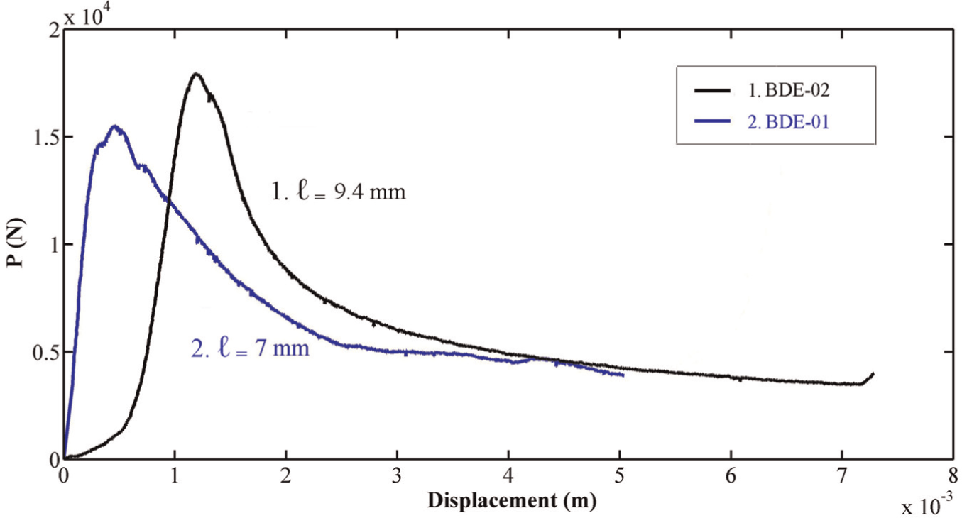
Experimental diagrams of the axial load–displacement of the empty brazen specimens BDE-01 and BDE-02 with the different initial free lengths.
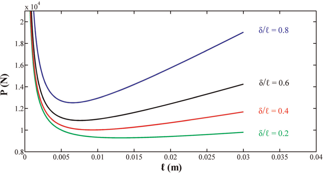
Variation in the axial load versus the initial free length of the tube in lieu of the different ratios of
Figure 7 shows number of created fold in the empty brazen specimens with the same wall thickness of 1 mm and inner diameter of 14 mm versus the initial free length. The results show that one and two folds were created in the same specimens with the initial free lengths of 14.8 and 15.5 mm. Therefore, the folding wavelength as an intrinsic parameter of the tube with the mentioned wall thickness and diameter is between 14.8 and 15.5 mm. It shows the importance of the new method to form a fold with a certain wavelength into the circular tubes.
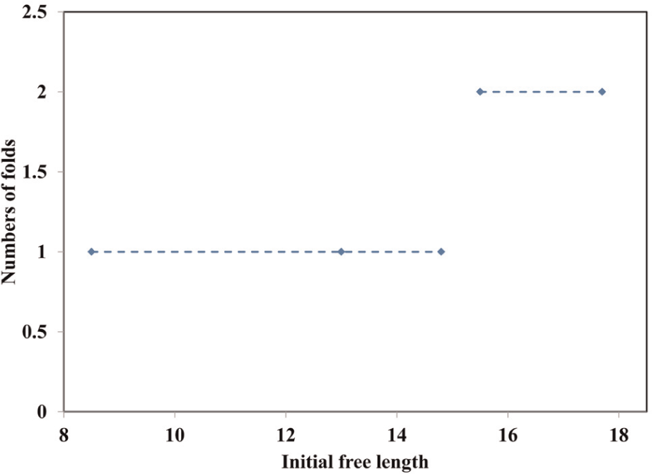
Experimental diagram of number of created fold in the empty brazen specimens with the same wall thickness and diameter versus the initial free length.
Effects of tube wall thickness
Figure 8 illustrates the experimental axial load per unit of the tube material flow stress versus the axial displacement of the samples AAE-01 and ABE-02. The samples are made of the aluminum alloys with the wall thicknesses of 2.5 and 2 mm, respectively. According to the figure, by enhancing the tube wall thickness, the required axial load to create a complete fold increases, too. In the investigated case, at axial displacement of 7–14 mm, the applied load/flow stress on the specimens AAE-01 and ABE-02 are 199.7 and 310.8 N/MPa, and therefore, an increment of 25% in the tube wall thickness causes increment of the axial load/flow stress approximately equal to 55.63%. Also, reviewing of equation (22) shows that the theoretical analysis predicts increase in the axial load due to the tube wall thickness increment. Therefore, the similar trends are concluded from the theory and experiments.
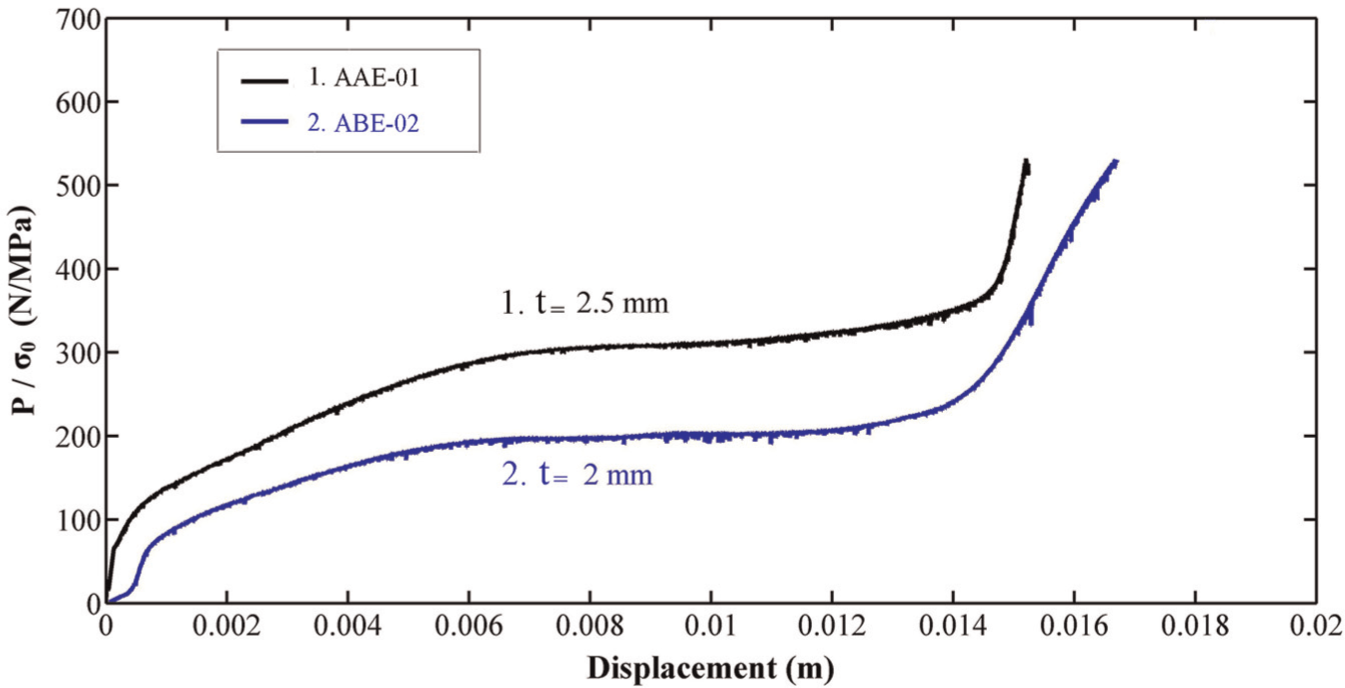
Experimental diagrams of the axial load/flow stress ratio versus the axial displacement of the empty aluminum specimens AAE-01 and ABE-02 with the different wall thicknesses.
Effects of tube diameter
In Figure 9, experimental diagrams of the axial load/flow stress–displacement of two brazen specimens BCE-01 and BBE-02 are compared. Diameters of the specimens are different, but other geometrical characteristics are the same. By considering the graph, it is concluded that by increasing the tube diameter, required axial load to create a complete fold increases, too. For example, at the same displacement of 2 mm, the axial load and flow stress of the mentioned specimens are equal to 10.41 N and 15.18 MPa, respectively and it shows an increment of 45.82% due to an increment of 58% in the tube diameter. Also, the theoretical equation (22) shows increment of the axial load due to increment of the tube diameter.
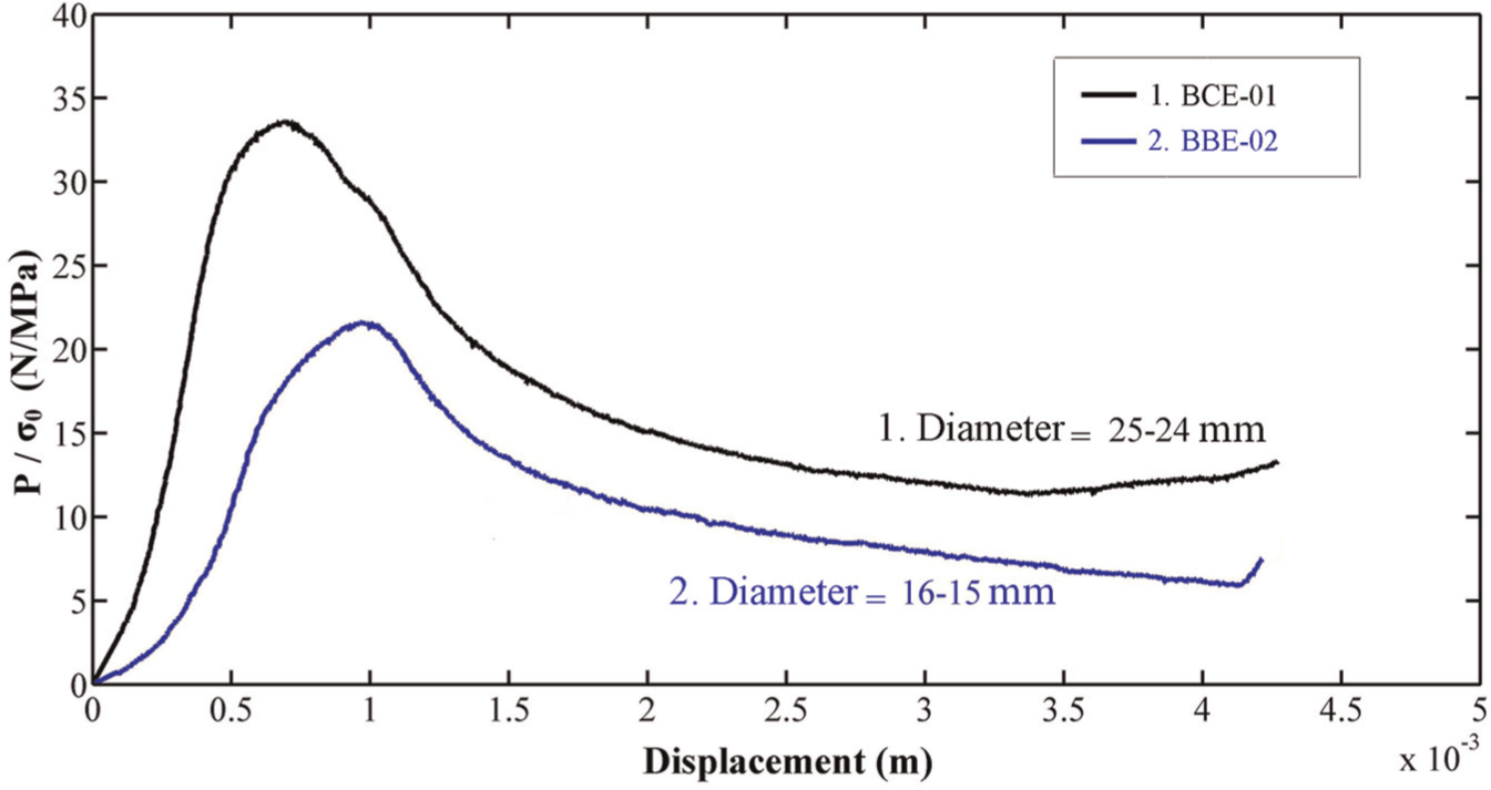
Experimental diagrams of the axial load/flow stress ratio versus the axial displacement of the empty aluminum specimens BCE-01 and BBE-02 with different diameters.
Effects of PVC Teflon filler
Desired purpose of this article is introducing a new method of cold metal forming for creating only one fold in the circular tube with a certain wavelength. Experimental results show that when initial free length of the tube reaches a critical length, more than one fold forms in the tube. Therefore, range of the initial free length of the tube for creating only one fold is limited. The PVC Teflon filler is used to increase initial free length of the tube for just one fold creation. According to the experimental measurements, Poisson’s ratio of the PVC Teflon filler is approximately equal to 0.5. It is the largest value of Poisson’s ratio for a homogenous isotropic solid, according to the theoretical analysis. By applying the axial compression load on the Teflon-filled constrained tubes, the considerable barreling process appears in the PVC Teflon filler and it exerts the internal pressure on the internal surface of the free part of the tube to prevent more than one fold formation. Figure 10 shows the experimental load–displacement diagrams of the empty and Teflon-filled specimens BEE-01 and BEF-01 during the process. Material type, wall thickness and inner diameter of the specimens are the same, but the initial free lengths of the empty and filled specimens are different and, respectively, equal to 15.5 and 24 mm. The specimen BEF-01 was filled by a solid cylinder of PVC Teflon with the initial diameter of 28 mm. To achieve a desired formation, initial length of the Teflon filler was selected to be 10 mm longer than the tube. Comparison of the load–displacement curves of the empty and filled specimens shows that in the empty sample, an initial incremental trend and then a decreasing trend are appeared in the graph, but in the Teflon-filled specimens, the incremental trend of the axial load is held all over the process. Experimental observations show that although initial free length of the empty tube is 35.4% smaller than the filled tube free length, two folds are formed in the empty tube and only one fold is created in the filled specimen. It shows advantage of using the PVC Teflon filler into the circular tubes to control and increase the folding wavelength during the cold metal forming in comparison with the similar empty one.
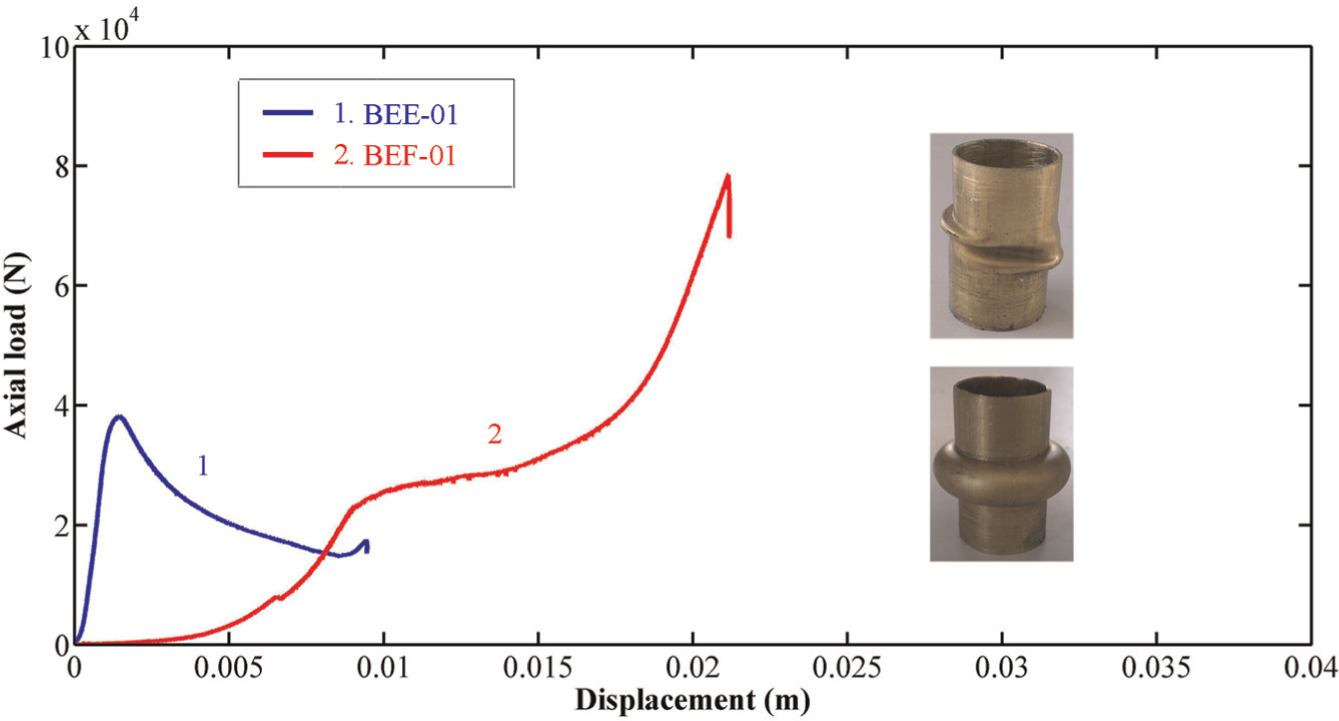
Experimental diagrams of the axial load–displacement of the empty and Teflon-filled brazen specimens BEE-01 and BEF-01.
Experiments show that in the Teflon-filled constrained metal tubes, by increasing the initial free length of the tube, more than one fold forms in the specimen. But experiments show that an attractive process occurs during the forming process on the PVC Teflon-filled specimens. When the initial free length of the Teflon-filled tubes is selected longer than a determined value, first, two folds with a certain wavelength form in the tube, but, by continuing the loading, the applied internal pressure by the compressed Teflon on the internal surface of the tube transforms two initial folds to a single fold by the double wavelength. Figure 11 illustrates the experimental load–displacement diagram of the Teflon-filled specimen BEF-02 with the initial free length of 34 mm. The other geometrical characteristics of the sample are similar to the specimen BEF-01. Due to the high initial free length of the specimen BEF-02, two folds create in the tube during the plastic deformation. But by continuing the axial deformation, two folds transform to one fold with the double wavelength. Two relative maximums of the axial load in Figure 11 assert two folds formation in the specimen.
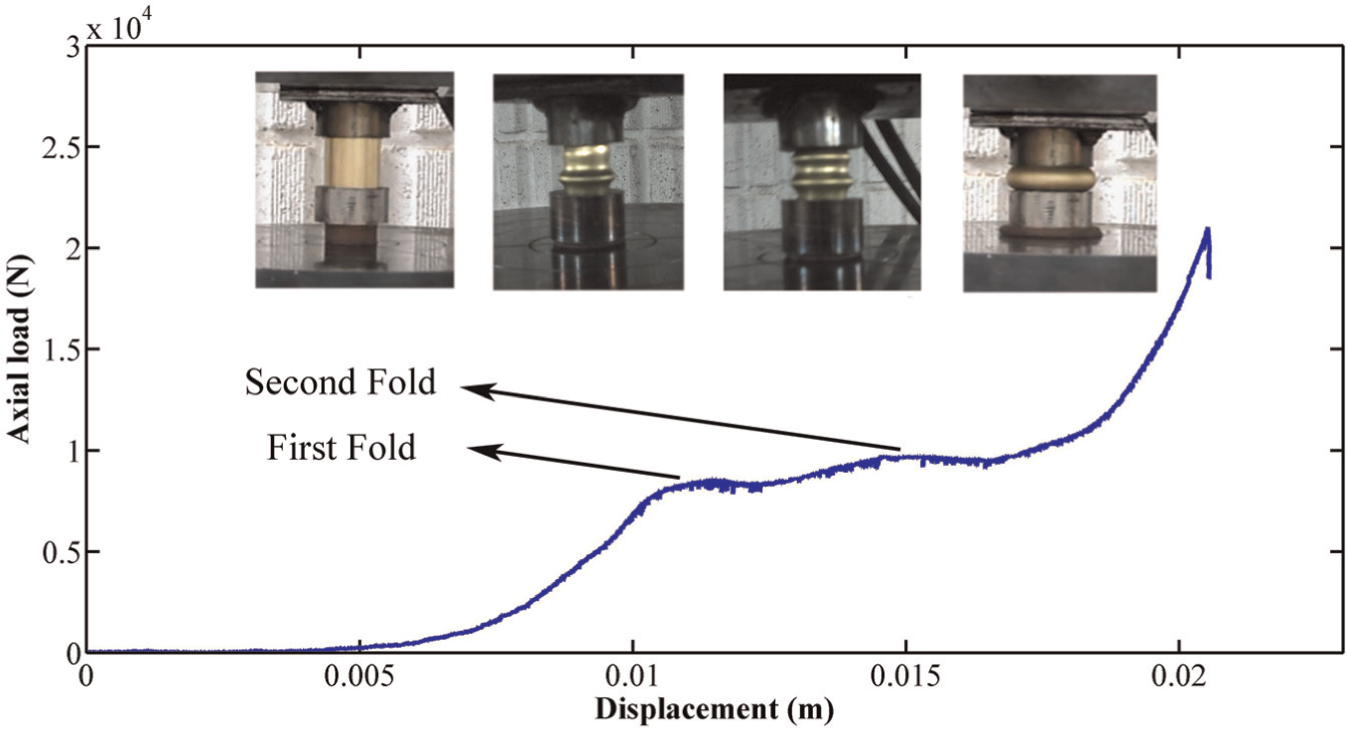
Experimental diagram of axial load–displacement of the Teflon-filled brazen specimen BFF-02.
The mentioned procedure for the brazen tube BEF-02 with the outer diameter of 30 mm and wall thickness of 1 mm is also employed for the brazen specimen BFF-01 with the outer diameter and wall thickness of 18 and 0.5 mm, respectively. Experimental results show that two folds are created in the empty specimen BFE-01 and also in the filled specimen BFF-01. But by increasing the axial displacement, two formed folds in the Teflon-filled specimen transform to a single fold. Therefore, based on the introduced method of metal forming, wavelength of the created fold is controllable and predictable.
Generally, there are different methods29,30 to shape specimens into a desirable form. In this work, a new forming method was introduced to create a fold with a desirable wavelength in circular metal tubes. By placing an empty circular metal tube between two rigid punches and applying axial compression force, during the plastic deformation, two different conditions occur that are dependent on initial free length of tube between two punches. In the axial compression test on a circular tube between two rigid platens, each fold is formed in the tube with an intrinsic wavelength that is dependent on material type and geometrical dimensions of the specimen. In the introduced forming method of this article, when initial free length of the specimen is shorter than intrinsic wavelength, just one fold is created in the tube, and when a constrained empty sample with initial free length longer than intrinsic wavelength is used in the forming process, more than one fold is created in the sample and so, its wavelength is not controllable. However, the experimental observation of this work shows that by filling the samples with the PVC Teflon filler, when initial free length of the constrained tube is selected longer than intrinsic wavelength, just one fold with a wavelength equal to the initial free length is created in the constrained tube. Also, when circular tube is prepared with an initial free length too longer than its intrinsic wavelength, first, two folds are formed, but, by continuing the loading, the applied internal pressure by the compressed Teflon on the internal surface of the tube transforms two initial folds to a single fold by the wavelength equal to tube initial free length.
Conclusion
Sometimes, the aim of energy, load and deformation mode analyses during the folding or other mechanisms of energy absorption is to achieve a special formation mode. This work was performed to determine required load for creating a desirable shape into the circular metal tubes. Ability of creating a fold in a circular metal tube with a certain wavelength is the main reason of using the controlled deformation mechanism.
This article presents a new theoretical deformation model of constrained circular tubes during a fold formation in the quasi-static condition. A new theoretical analysis was derived to predict the instantaneous axial force of the constrained circular tube between two rigid punches during the folding process. Comparison of the theoretical prediction and the experimental results showed an acceptable correlation.
Also, the experimental observations show that the plastic deformation of circular tube could be controlled using two rigid dies during the folding process and using PVC Teflon as the filler. The introduced process can be used to create a fold with a certain wavelength into the circular tube, instead of the intrinsic wavelength of the tube.
Footnotes
Acknowledgements
The authors gratefully acknowledge Strength of Materials Laboratory in Yasouj University.
Declaration of Conflicting Interests
The author(s) declared no potential conflicts of interest with respect to the research, authorship, and/or publication of this article.
Funding
The author(s) received no financial support for the research, authorship, and/or publication of this article.