
Abstract
This study refers to the study of the ball-burnishing process assisted by vibration. This study begins by considering that this vibration helps to make the development of this finishing process easier because it helps to deform the workpiece material more easily. Because a similar tool is not available in the market, a tool that can perform the study needed to be designed, characterised and manufactured to conduct the study by considering the critical components that are involved in the design and the physical model that characterises the operation. For these criteria, the tool operation is also characterised by evaluating the surface roughness that remains after the process occurs. Workpieces of aluminium and steel were used for the experimental validation. These results were compared to those obtained using the same tool without vibration. The roughness results obtained using the ball-burnishing vibration-assisted process improve compared to those obtained using the process without assistance for both materials tested.
Keywords
Introduction
Currently, industry features many mechanical components for machine tools, automobiles, planes, trains, boats, moulds, forming dies and many other pieces, which should have a good surface roughness, a geometric tolerance level, a surface hardness with a high degree and significant mechanical strength values to be able to work, even in hard conditions. Many traditional processes are being studied to improve and adapt them to new difficulties found in industry. Furthermore, parallel studies have provided novel solutions for longer life cycles of many components that undergo, for example, daily high rates of wear or are subject to the effect of cyclical forces. In recent years, the amount of research associated with different processes aiming to produce these pieces with appropriate features that allow them to meet these benefits has markedly grown.
The ball-burnishing process meets all these requirements. It can meet many of these needs much more easily than other processes. This process is also limited in terms of the materials that can be burnished and how their properties vary. Ball-burnishing is defined as a technological operation that consists of plastically deforming surface irregularities by the action of the force exerted by a ball. 1
This process could be performed with a conventional tool 2 or be assisted by vibration, as presented in this study. The vibration-assisted process affords a greater dislocation movement of the material workpiece, which allows us to work on harder materials with less force and even improve the results of the process. 3
The current market does not offer a tool that uses the assistance of vibration during the ball-burnishing process. Therefore, a prototype tool capable of performing the above process has been designed and manufactured. This tool constitutes the main contribution of this article.
Therefore, this article aims to study the behaviour of a ball-burnishing vibration-assisted tool. To this end, we first describe the tool design via the study of its fundamental parts. An analysis of the elements that provide the vibration via a physical model is then performed, which reflects that they constitute the essential elements for the tool operation.
Subsequently, the model was experimentally validated. Finally, practical tests were performed to determine the surface roughness values obtained with the developed tool. The practical tests were carried out using workpieces of aluminium A92017 and steel G10380.
Because the tool described herein is not currently available in industry, its implementation could be of great importance because it fulfils significant demands, such as obtaining parts with good mechanical properties and hard surfaces using lower strength. This provision would lower energy consumption, which is very relevant today. Vibration is widely used to assist the conventional manufacturing process in modern industry4–6 as a method to improve the surface quality of workpieces.
Development study
Schematic functional description
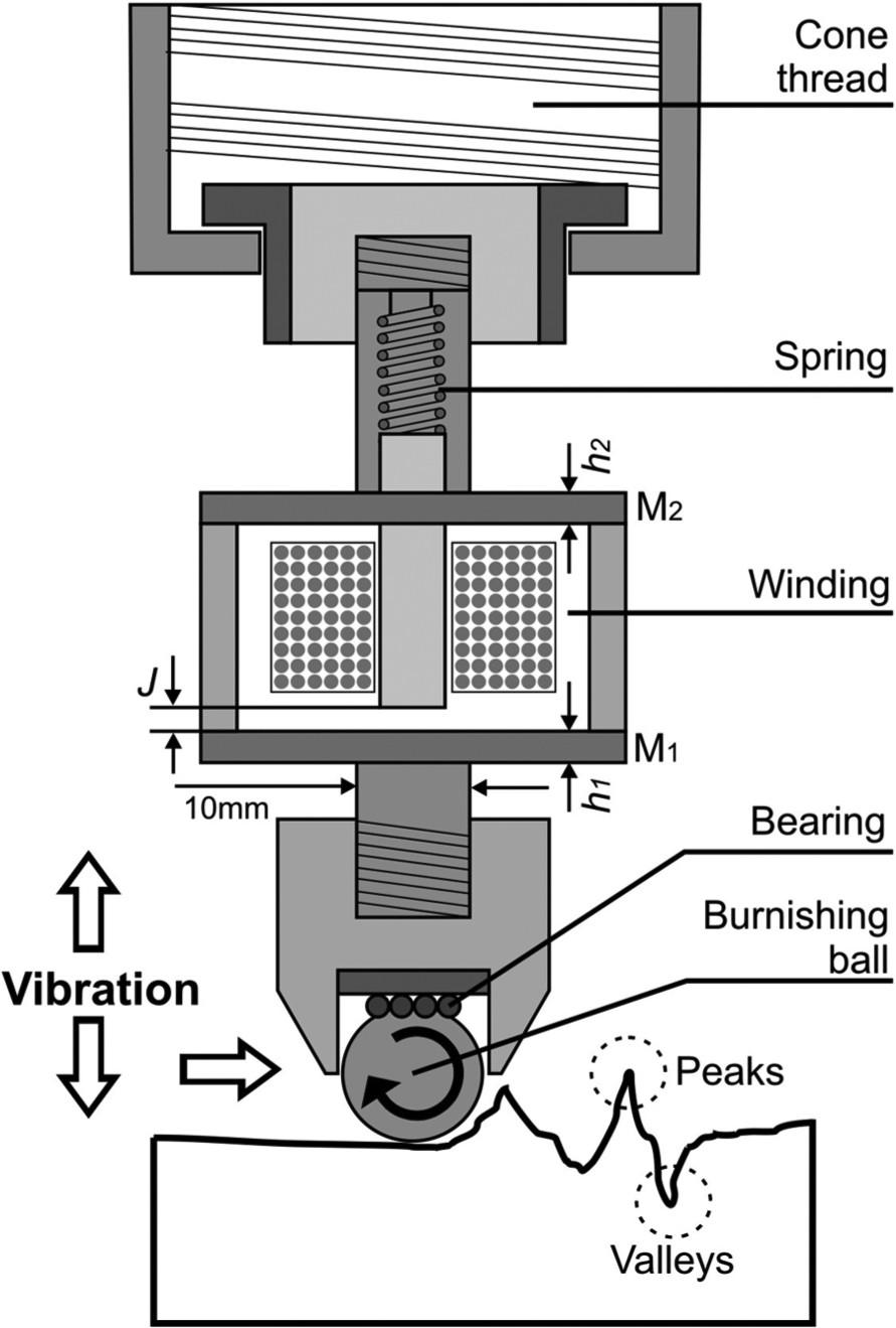
Before developing the tool components that affect the study of the ball-burnishing process, the method to introduce the vibrations must be considered. In modern industry, piezoelectric transducers are the most widely employed vibration generators. In this case, vibrations are generated by an electromagnetic transducer that is used to convert alternating current into a variable magnetic field. This field produces an attraction cyclical force on metal plates M1 and M2 with thickness h1 and h2, deforms them and causes a vibration, whose frequency is determined by the magnetic field (Figure 1).
Functional diagram of the vibration system.
Figure 1 shows how the tool can be easily installed using an International Organization for Standardization (ISO) cone in the same computer numerical control (CNC) machine where the piece has been previously machined. The thread cone is fixed to the tool body, which consists of a cylinder that contains a spring housed inside. This spring is deformed by the effect of the vibration, but it ensures the maintenance of a constant force throughout the process. The spring is joined to a rod that is in contact with the coil core. The coil is inside the cylinder closed on both faces using two plates, M1 and M2. These plates are coupled and vibrate at a predetermined working frequency. They transmit this vibration to the bottom part of the tool, where the ball-burnishing is placed. The ball is in contact with a bearing, which facilitates its free rotational movement. Several spheres that are 2 mm in diameter form the bearing, which is responsible for transmitting the vibration generated by the coil.
The effect of a hard ball that is 10 mm in diameter plastically deforms the workpiece. The interaction between the hard ball and the workpiece under the action of a constant and normal force is strong enough to modify the surface topography of the treated material.
Significant design criteria
Starting from these premises, monitoring certain parameters that will determine the correct functioning of the tool is important from the standpoint of design, as specified in the scheme of Figure 1. These elements of special interest are the following:
The thickness of plates M1 and M2;
The interrelationship that is established between them;
The J gap, which is defined as the distance between the coil core and the centre of the M1 plate. Conceptually, this distance must be greater than the maximum relative plate deflection between M1 and M2 that is experienced during operation of the tool;
Therefore, this article seeks the maximum relative deflection between M1 and M2 plates to estimate the optimum value of the gap. With this optimised value, the magnetic field strength does not significantly decrease and is then transferred to the vibration plates and the ball-burnishing process;
At this point, studying the behaviour of the deflection when both plates are working (M1 and M2) is useful. Moreover, this deflection value will also depend on the thickness of the two plates. Therefore, various thicknesses were evaluated throughout the study to determine the appropriate thickness.
The following assumptions were made to characterise this tool:
The amplitude and frequency of the vibration are directly generated by the magnetic attraction force generated by the coil.
The deformations of the plates are in an elastic regime; therefore, the material properties, such as Young’s modulus and Poisson’s ratio, are considered constant.
The tool should work in a resonant mode whose frequency must be estimated.
The plate considered in this study is a rigid thin plate 7 because the plate diameter, D, is 53 mm, the plate thickness, h, is less than 5 mm and the maximum plate deflection, w, is less than 0.08 mm. With these values, the aspect ratio, D/h, and the ratio, w/h, are reduced to the following

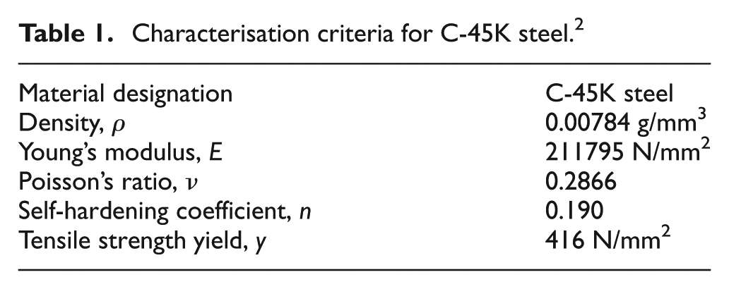
The model developed in this study is based on the classical theory of Kirchhoff. 8 Therefore, assuming that the deformations in solids to be considered are infinitesimal, the relationship between the stress components and the strain components depends on the solid compound material. For an elastic and isotropic solid, the constitutive equations take the form of Hooke’s generalised law. 9 The assumption of an isotropic material is suitable to define the behaviour of the C-45K steel (according to standard EN 10083-2), which was used to manufacture the vibrating plates and whose characterisation is specified in Table 1.
Characterisation criteria for C-45K steel. 2
The equations that relate the stress components to the deformation components are often called constitutive equations. Hooke’s law is used for a reference system in polar coordinates with axial symmetry. 7
Model of the coupled plates
In addition to the influence of the vibration generator, other elements with equal importance influence the global behaviour of the plates of the tool under consideration. When the tool begins to apply a force on the burnishing tool, the M1 and M2 plates are deformed depending on the direction of the force, but in opposite directions to each other. The deformation produces a deflection between the two plates. The coupling of the deformation of the plates must be studied. To this end, a series of successive steps that will allow a drill-down analysis of the elements to establish the functioning of the entire system are necessary.
Differential equations (2) and (3) are obtained by deducing the equations of all theories considered. These equations predict the deflection, w, of each of the circular plates depending on the radius, r, and time, t. These equations are the basis of the model to be developed


The boundary conditions are defined in equation (4)

P is the vertical load distribution and is defined by equation (5). The value of the forcing function is constant

P0 is the oscillatory forcing function produced by the magnetic field.
Furthermore, the flexural modulus of the rigidity plate, K, defined in Ventsel and Krauthammer, 7 is shown in equation (6)

Solution to the static problem
The static problem is solved to assess the resulting deflection of the plates as a result of a constant burnishing force. This problem does not consider the force due to superimposed vibration. The static deflection of the plates is a condition that affects the tool design. The burnishing force must produce a resulting deflection value lower than the J gap.
To perform this analysis, we implement the Lazarus language software, which leads to a solution that has been obtained via the finite difference method. We used 50 nodes with a 0.000002 s integration step.
Using this software, we performed a comparative study of the maximum deflection of the M1 plate evaluated for three thicknesses, h (1, 1.5 and 2 mm) and three different burnishing forces, F (15, 30 and 50 N). The values of these burnishing forces were obtained from previous studies. 2
The load was applied, as shown in Figure 2(a). For example, the plates are known to proportionately increase when the force increases. Likewise, the deflection of plates inversely correlates with the thicknesses. Figure 2(b) shows the graphs of the simulation in which the differences in the h − F relationships for the smallest of all the forces used can be observed. When studying the behaviour of the other plate (M2), a symmetrical deflection of M1 was observed, but with the opposite sign.
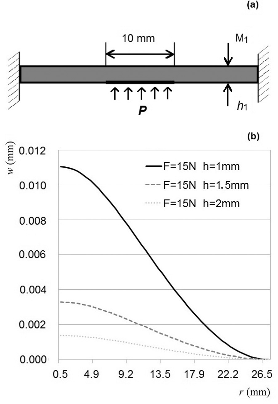
Representation of M1 plate deformation for different thickness conditions.
In summary, any thickness under study may be valid for these conditions because even a 2-mm plate showed a relative deflection that is sufficient to modify the surface roughness of the workpiece to be burnished. Of the three cases, a thickness of 2 mm minimised the complexity for the manufacturing of the plate.
Numerical solution to the stationary problem
The problem under study is truly dynamic because the forces involved change over time throughout the process. In this case, the maximum deflection reached by the tool plates can be determined for each of the conditions stated in the study, which are derived from the analysis of the static behaviour.
The resulting vibration of the vibration coupling of the two plates needs to be analysed. The analysis is performed for the following cases:
M1 = 1 mm and M2 = 1 mm;
M1 = 1 mm and M2 = 2 mm;
M1 = 2 mm and M2 = 1 mm.
The analysis begins by considering a forced vibration introduced into the tool by a vibration generator. In this case, the resonance frequencies can be estimated (first vibration mode). We used this first vibration mode for the first test and because it is easily achieved using the vibration generator. To this end, the developed software was used once again to obtain the resulting relative deflection values when coupling the two vibration plates for the first mode of vibration.
The relative deflection is greater when the two plates are 1 mm thick, which is to be expected. When the plates are 2 mm thick, the deflection is smaller. The behaviour of the plates was analysed for a frequency sweep between 50 and 10,000 Hz. Nevertheless, we decide to use plates that were 2 mm thick because they are more easily manufactured. Figure 3 shows the results for the selected case (h1 = h2 = 2 mm).
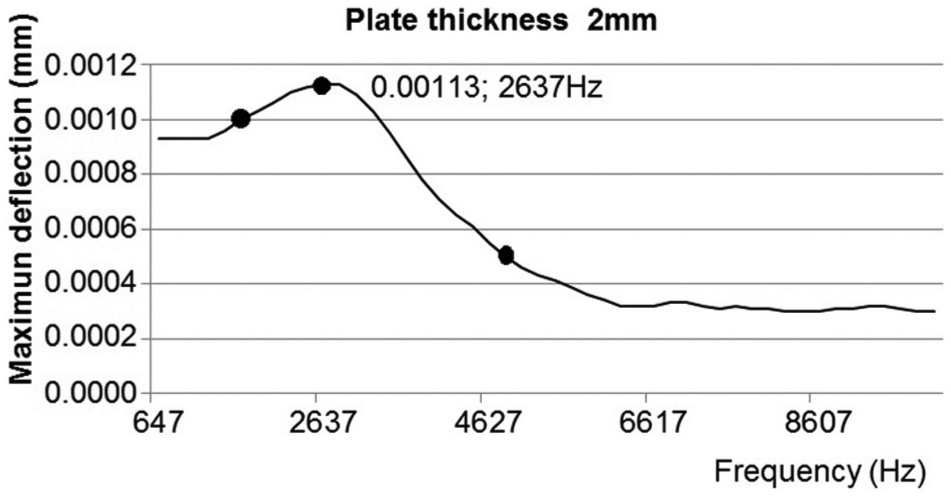
Sweeping the sinusoidal excitation frequency of the M1 plate, contrasted with the experimentally measured values at 2600 Hz.
Experimental check of the plate deflection
To verify the actual relative deflection, the M1 plate was studied when the tool was subjected to the influence of the sinusoidal driver. A displacement digital electronic display unit produced by MARPOSS was used. The sensor was placed on the central point of the tool shank, which is the maximum displacement area, to take the appropriate reading when M1 is vibrating at 2600 Hz (Figure 3). This frequency was determined from the simulation results of the deflection for M1 = 2 mm.
According to the terms of the theoretical study, the maximum relative deflection of the plate designed for the tool was determined to be 0.0012 mm at 2600 Hz, as shown in Figure 3. This value corresponds to what is shown in the graph, which shows a maximum deflection (0.0013 mm) at 2637 Hz. These three points are indicated on the graph in Figure 3.
To obtain various experimental values, the deflection mode resonance measurements were taken at various frequencies. A reading of 0.0010 mm could be obtained at 2200 Hz, and another could be obtained from 0.0005 mm at 4800 Hz. Both results corroborate the behaviour of the curve obtained from the simulation. Figure 4 shows the prototype of the manufactured tool, taking into account all the design criteria described above.
Prototype of the ball-burnishing vibration-assisted tool.
Preliminary experiments to characterise the tool operation
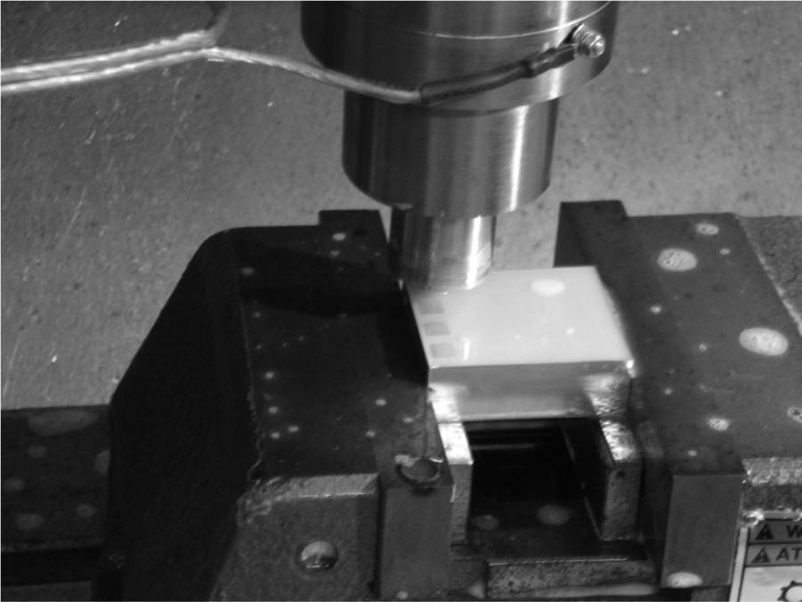
To evaluate the behaviour of the prototype tool that was designed, burnishing tests on two pieces of aluminium A92017 and two pieces of steel G10380 were developed (Figure 5). The dimensions of said workpieces were 54 × 44 × 15.5 mm. These pieces were milled using a hard metal spherical cutter measuring 8 mm in diameter rotating at 3000 min−1 with a feed rate of 330 mm/min, a depth of pass of 0.5 mm and a lateral swath width of 0.5 mm. To perform the burnishing process, the prototype tool was placed at the head of the CNC Lagun MC600 milling machine.
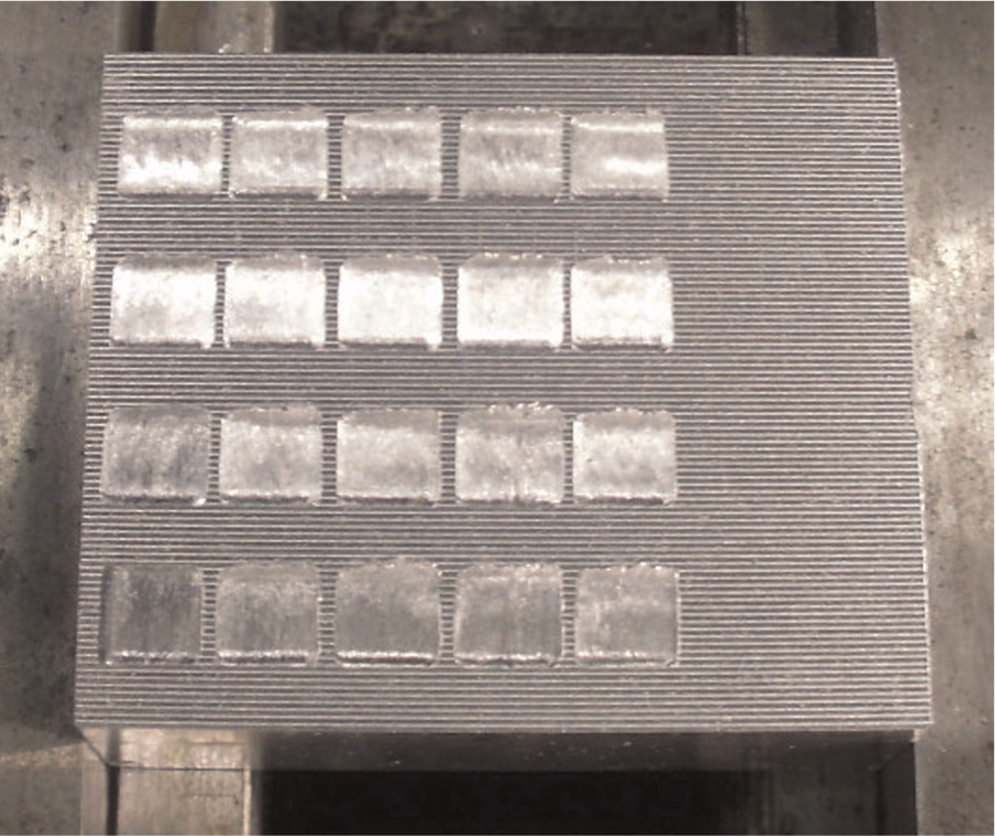
Workpieces used after ball-burnishing.
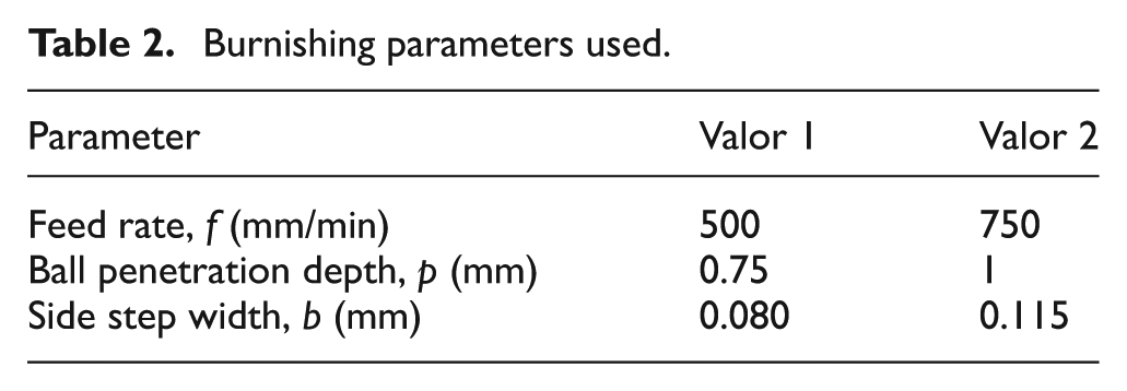
Conventional burnishing and vibration-assisted burnishing were compared for the same prototype tool. The process parameters used (shown in Table 2) were defined in relation to those obtained by Travieso-Rodríguez et al. 1 To obtain the vibration, the tool was coupled to a vibration generator with coupled plates vibrating at a frequency of 2500 Hz (the sinusoidal excitation frequency that produces the resonance of the plate), which is defined in the simulation for the thicknesses, h, in this study (Figure 3).
Burnishing parameters used.
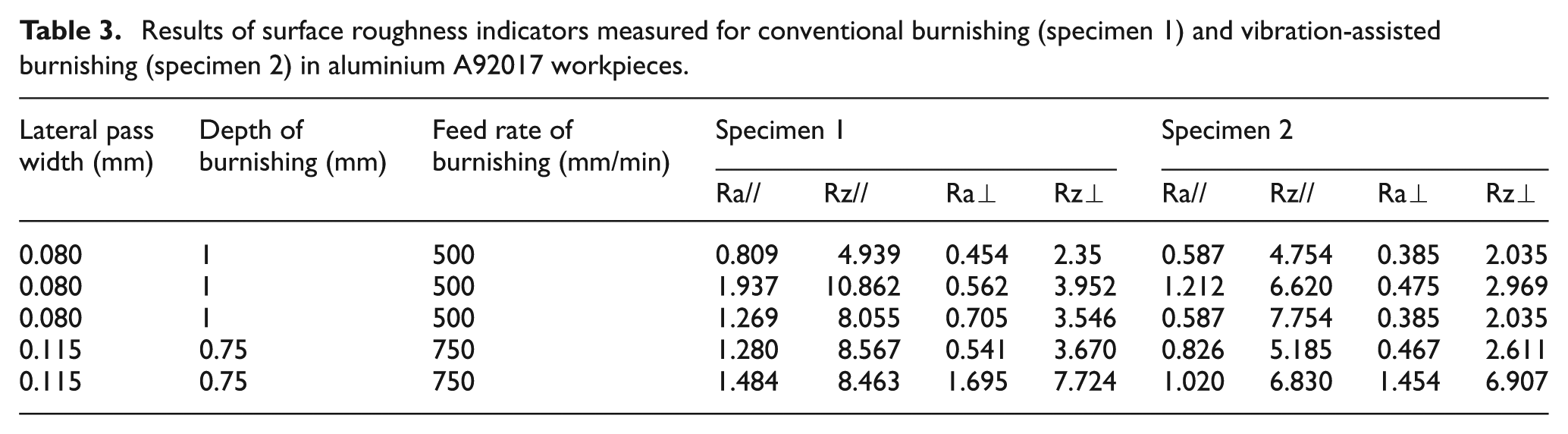
After performing both burnishing processes on the workpieces, the resulting surface roughnesses of the burnished specimens were measured. Indicators measured the average surface roughness (Ra) and the maximum roughness total evaluation length (Rz) in two directions that were parallel and perpendicular to the advancement direction of the prior milling operation. Subsequently, a comparison between the values was obtained. Tables 3 and 4 show examples of these measurements and their comparisons.
Results of surface roughness indicators measured for conventional burnishing (specimen 1) and vibration-assisted burnishing (specimen 2) in aluminium A92017 workpieces.
Results of surface roughness indicators measured for conventional burnishing (specimen 3) and vibration-assisted burnishing (specimen 4) in steel G10380 workpieces.
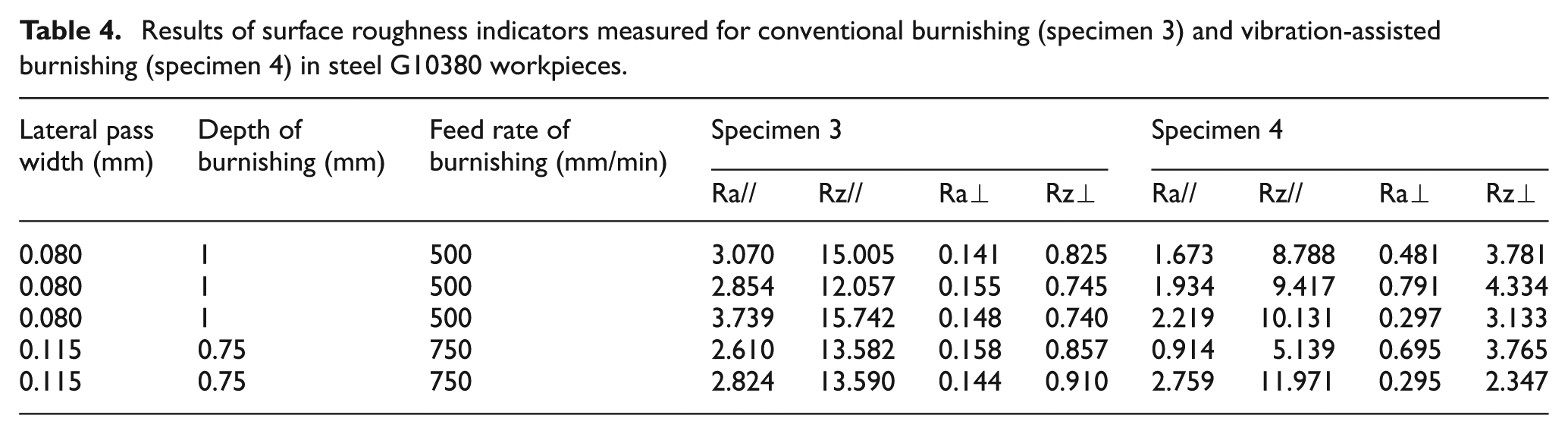
As shown in the above results, the surface roughness values obtained with the vibration-assisted tool on the burnished surfaces are better than those of the tool without vibration. For the aluminium workpieces, Ra// was improved by 37%, Rz// was improved by 21%, Ra⊥ was improved by 21% and Rz⊥ was improved by 24% on average; for the steel workpieces, Ra// was improved by 38%, Rz// was improved by 35%, Ra⊥ was improved by 33% and Rz⊥ was improved by 42% on average.
More experiments must be conducted to further evaluate the behaviour of the tool for different working conditions, other materials and other frequencies than those found in the theoretical development before being synthesised. Other parameters that help to evaluate the burnishing results have also been suggested as parameters that should be examined, such as hardness and the residual stresses. Nevertheless, the measurements obtained herein serve to preliminarily evaluate the tool.
Conclusion
The ball-burnishing vibration-assisted process was studied. The changes in the surface roughness obtained when using the vibrations to assist the process were also analysed compared to when the process was performed without the assistance of vibration.
A method to characterise the plates involved in the design of a tool to be used in the ball-burnishing vibration-assisted process was successfully developed.
Reliable numerical solutions were obtained to predict the plate deflection values that can be used to optimise the different basic design parameters: the thickness of the plates, the gap and the working frequency of the vibration generator.
A completely new tool for the market was designed, characterised and manufactured, and the first experimental results to demonstrate improvements compared to the conventional burnishing process for the surface roughness parameters were evaluated.
Footnotes
Declaration of conflicting interests
The authors declare that there is no conflict of interest.
Funding
This study was financially supported by the Ministry of Economy and Competitiveness of Spain through grant DPI2011-26326 (J-01686), which is greatly appreciated.