
Abstract
Elastic connection of spindle–tool holder is one of the weak points of spindle systems. It directly affects dynamic characteristics of machining system. Stiffness modeling of spindle–tool holder is the key problem in dynamic analysis of spindle system. Considering the influence of cutting force, an analytical method combining classic elasticity theory with fractal theory is proposed to estimate the contact stiffness at the spindle–tool holder interface. The effectiveness of the proposed method is validated by self-designed experiment. An approximate model is proposed to replace finite element model in the processing of identification of contact stiffness of spindle–tool holder in order to save calculation time. On that basis, effects of cutting force on contact stiffness of spindle–tool holder are investigated in this article. The conclusion can be drawn that cutting force has great effect on stiffness of spindle–tool holder. Contact stiffness of spindle–tool holder can be obtained by the method proposed in this research on the premise of not making prototypes or utilizing hammer-hitting pulse-inspirit method. The calculating model and method in this article can be implemented to solve the contact stiffness at the spindle–tool holder during the design stage.
Introduction
Spindle system is an important component of machine tools. It is the component that directly affects machining. Because cutting frequency is close to the low-order lateral natural frequencies, lower order lateral vibration mode of spindle systems is the decisive factor for cutting vibration. Machining quality and cutting ability of machine tools are greatly determined by dynamic characteristics of spindle system.
Dynamic model of spindle systems needs to be established in order to obtain dynamic characteristics of spindle systems during the design stage. Elastic connection of spindle–tool holder is one of the important joints, so contact stiffness modeling of spindle–tool holder is the key problem in dynamic analysis of spindle system.
Many works have been conducted on solving and identifying stiffness of spindle–tool holder. Stiffness of the system formed by the machine tool, shank and tool holder, the collet and tool under cutting forces was studied in Salgado et al., 1 and the results of this study showed that the stiffness of both the machine and the connection in the machine–spindle–tool holder–tool system has a similar importance in the displacement of the tool tip (subjected to a cutting force) to the deflection of the tool itself. Deformations at the real working condition were given. The dimensional errors resulting from tool deflection in the high-speed milling of hardened steel surfaces were investigated in Lacalle et al. 2 The effects of various factors on this dimensional error were given. Schmitz and Burns 3 predicted frequency response function (FRF) of tool holder–tool component using receptance coupling method and established two components’ model which provides a valid approximation for a flexible tool clamped in a stiff spindle-holder. Schmitz and Duncan 4 applied receptance coupling method in dynamic modeling of spindle–holder–cutter elastic connection. Mehdi Namazi et al. 5 identified stiffness of spindle–tool holder by testing response function, and the identified stiffness was introduced to establish the whole model of the system. The accurate dynamic model was finally obtained. Budak et al. 6 and Özşahin et al. 7 established dynamic model of spindle–holder–cutter system using receptance coupling substructure analysis (RCSA) method8–10 in their own research. FRF at the tool tip was adopted to deduce complex stiffness matrix of spindle–tool holder. Dynamic parameters of spindle–tool holder were identified. Mohammad R. Movahhedy and Javad M. Gerami 11 established dynamic model of spindle–tool holder including linear stiffness and bending stiffness of the joint. The optimization method based on genetic algorithms was employed to identify dynamic parameters. However, the stiffness identification of spindle–tool holder is based on experimental results in the research above. These methods could not be applied in evaluating the stiffness of spindle–tool holder during the design stage.
Gao et al. 12 proposed a semi-analytical method combining classic elasticity theory with Yoshimura integral method which was used to estimate the contact stiffness at the spindle–tool holder interface at the status of high speed. The effectiveness of the proposed method was validated by the experimental data in Namazi et al. 5 A dynamic model of spindle–cutter coupling system was also established at the status of high-speed rotation. The effects of the contact stiffness reduction due to rotation of the spindle on dynamic characteristic of the system were also investigated. But contact stiffness is solved by contact stress distribution according to Yoshimura integral method. Yoshimura integral method could be used when contact stress is less than 4 MPa. When contact stress is greater than 4 MPa, Yoshimura integral method could not be adopted to calculate contact stiffness on the diminutive area. In the actual working condition, the method may become invalid because the contact stiffness of spindle–tool holder is usually greater than 4 MPa. Moreover, cutting force has effects on contact stress distribution, especially in heavy cutting condition.
On the basis of our former research, 12 an analytical method combining classic elasticity theory with Majumdar-Bhushan theory (MB) fractal theory is proposed considering the effect of cutting force to estimate the contact stiffness of spindle–tool holder in this research. First, contact stress distribution of spindle–tool holder under the actions of cutting force and drawbar force is solved by classic elasticity theory. Second, contact stiffness of the diminutive area is obtained by MB fractal theory. Finally, the contact stiffness of spindle–tool holder is calculated by integrating contact stiffness of diminutive areas. The effectiveness of the proposed method is validated by the self-designed experiment. Microscopic fractal characteristics of joints can be considered in this research, and physical mechanism of spindle–tool holder stiffness is studied. The effects of cutting force on contact stiffness of spindle–tool holder are also investigated in this article. Contact stiffness of spindle–tool holder can be obtained by the method proposed in this article on the premise of not making prototypes or using hammer-hitting pulse-inspirit method. The calculating model and method in this research can be implemented to solve the contact stiffness at the spindle–tool holder during the design stage.
Modeling
Solution for distribution of contact stress
Spindles and tool holders are both made of steel, and therefore, the elastic modulus, Poisson’s ratio and density of the two components are considered to be the same. According to the classic elasticity theory,
13
for an annulus, which has outside diameter b, inside diameter a and thickness
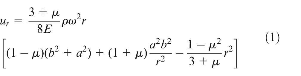
where r is the displacement between the certain node and the center, and E and
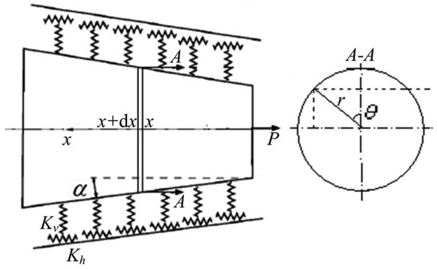
Figure 1 is the cross-sectional sketch of a certain kind of spindle–tool holder. The shape of spindle–tool holder is axisymmetric. The axial length of spindle–tool holder is much more than other sizes. Therefore, the problem of spindle–tool holder can be simplified to a plane strain problem. E is substituted by

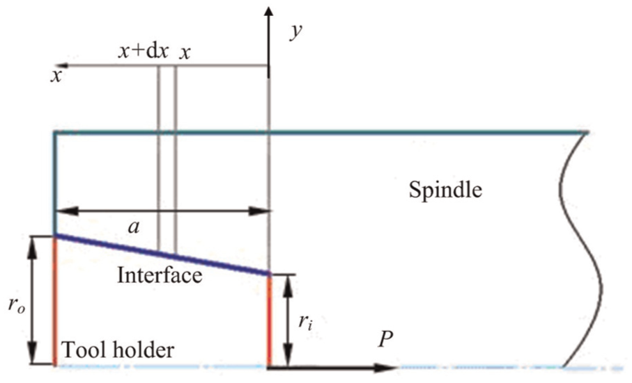
Sketch of spindle–tool holder.
where
For the spindle and tool holder which is described in Figure 1, the radius of the interface with x-coordinate as x can be expressed as r(x). r(x) can be obtained by linear interpolation. According to expression (2), radial displacements of nodes at the interface of spindle–tool holder can be expressed as
where
The contact of spindle–tool holder is an interference fit. The contact stress under the action of drawbar force and cutting force is 14

where
According to the equilibrium equation of tool holder, expression (7) can be drawn as
where
Solution for contact stiffness of diminutive area
The contact stiffness of every diminutive area can be solved by MB fractal theory. Fractal theory is a nonlinear analysis method. Many works can be conducted by this method. Regenerative chatter instability was described by delay differential equations in Fofana’s15–18 works, and the equations were studied via nonlinear analysis. Microscopic fractal characteristics of the interface can be considered by MB fractal theory compared with other methods. Actual physical characteristics can be taken into account by the theory.
When two solids whose interface looks flat contact with each other, contact between the two solids occurs only at some discrete diminutive area because of the actual rough surfaces. The asperity on rough surfaces can be simplified to a sphere. The contact area of asperities ac at the critical status of elastic deformation and plastic deformation can be expressed as
where
The relationship between deformation of asperities δ and its critical value δc is
where a is the contact area of the asperity. If a < ac , according to expression (9), δc < δ, and plastic deformation occurs on the asperity. If a > ac , δc > δ can be obtained, and elastic deformation occurs on the asperity.
According to MB fractal theory, normal contact stiffness of the diminutive area is 19
where
where
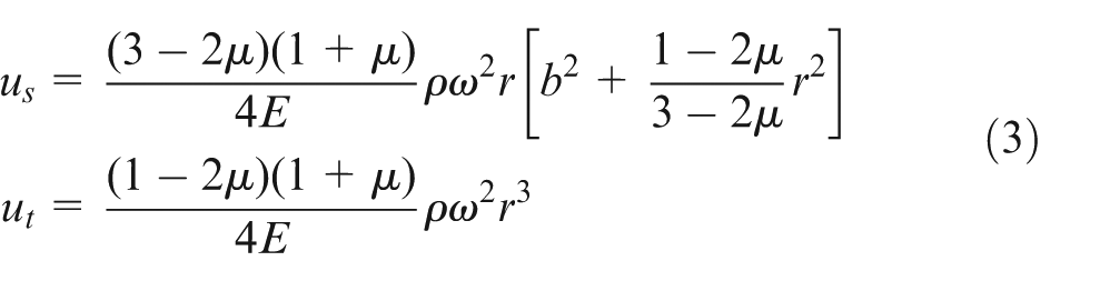
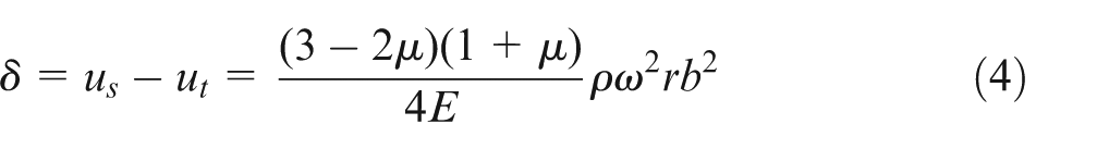
Shear contact stiffness of the diminutive area is 20
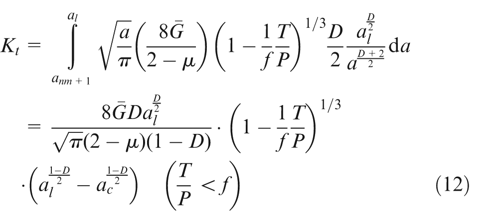
where
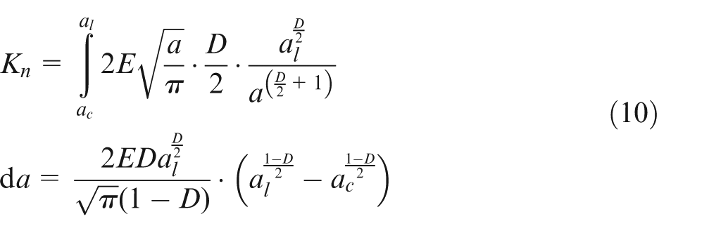
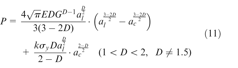
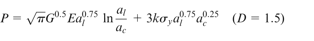
Determination of stiffness of spindle–tool holder
According to MB fractal theory, shear contact stiffness
Shear contact stiffness
Sketch of contact stiffness of the spindle–tool holder.
where
According to the relationship among springs, the contact stiffness at the spindle–tool holder interface can be expressed as
Validation
In order to validate the modeling approach for contact stiffness of spindle–tool holder, self-designed experiment is implemented.
Experimental modal analysis on the specimen
Because of limits of the structure, space and measuring-point arrangement of spindle–tool holder in actual machine tools, modal experiment cannot be conducted on actual machine tool structures. Moreover, the structure of actual spindle–tool holders is complicated. There are many influences in the test. It is not suitable to conduct experiments on actual machine tool structures to validate the validity of the method proposed in this research.
Topology of CAT40 is chosen as the prototype. The specimen is shown in Figure 3. Two parts of the assembly are designed to simulate spindle substructure and tool holder substructure. The specimen is made of 1045 (ASTM).
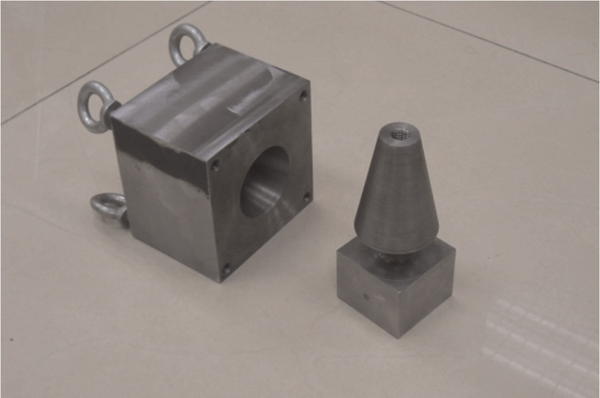
Specimen in the experiment.
Experimental modal analysis (EMA) on the specimen is conducted by DASP system which is developed by China Orient Institute of Noise & Vibration. Figure 4 is the sketch of EMA. Parts of the specimen are assembled by the bolt of M10 type. The experimental setup is shown in Figure 5. In order to eliminate the effects of support stiffness on the experimental results, the specimen is hanged by elastic ropes during the test. According to the preliminary analysis by finite element method (FEM), lower order modes of the system are local vibration of tool holder substructure (shown in Figure 6). Therefore, excitation and capture positions are all arranged at the end of the tool holder substructure. Hammer (MSC-1 type, with YFF 1-80 force transducer) is used to excite the vibration of specimen. Accelerometer (INV9824 type) is arranged to pick up the vibration of specimen. Bolt pretension is applied to simulate drawbar force. Bolt pretension is controlled and measured by torque wrench (J6177F type), as shown in Figure 7(a). Hammering method (shown in Figure 7(b)) is conducted to measure lower order frequencies of the system.
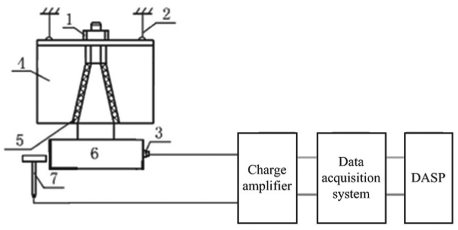
Sketch of EMA.
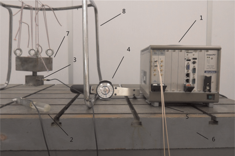
Experimental setup.
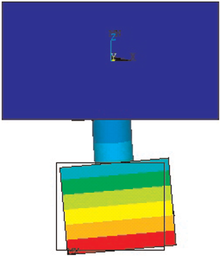
First-order mode shape of the specimen.
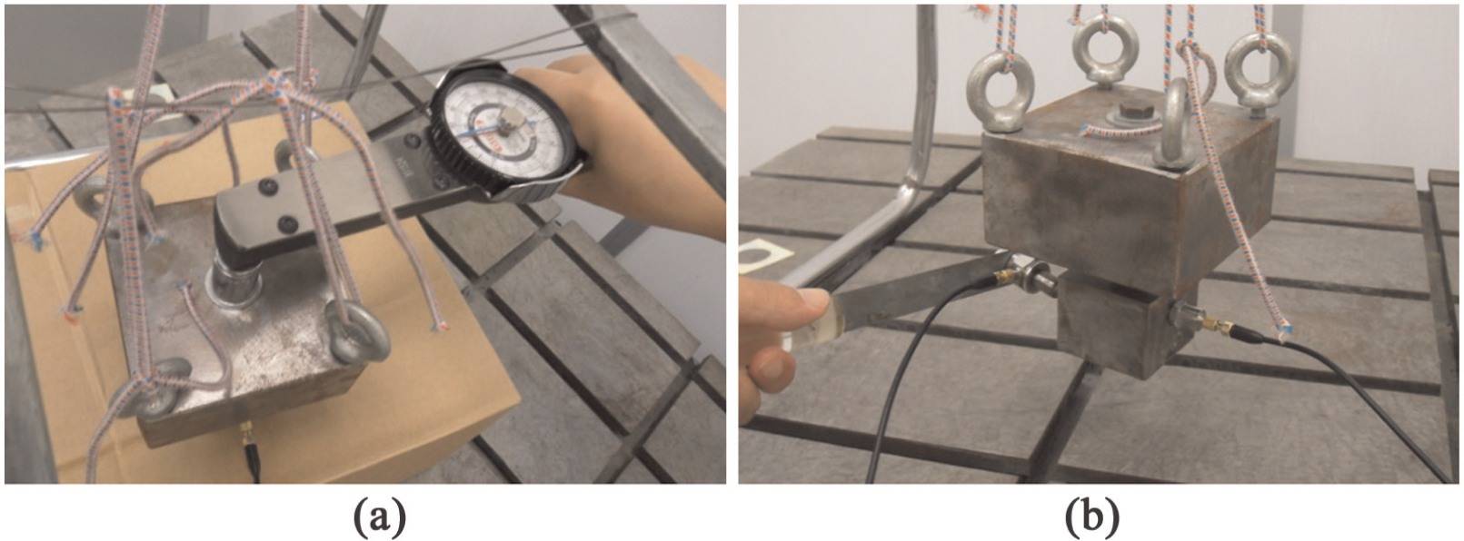
Experiment site: (a) bolt pretension measure and (b) hammering.
Identification of contact stiffness
Three-dimensional (3D) geometry model is constructed on the platform of Solidworks and imported to ANSYS to mesh. The model is meshed by 20-node SOLID186, as shown in Figure 8(a). The mesh should be satisfied that two nodes must exist at one position, where contact stiffness of spindle–tool holder is established, as marked in red in Figure 8(b). One of the two nodes i is affiliated to the spindle substructure, and the other node j is affiliated to the tool holder substructure. The stiffness is simulated by MATRIX27, which is established between each couple of nodes. The contact stiffness can be defined by keywords of MATRIX27. Because the specimen is hanged by elastic ropes during the experiment, any constraint is not applied in the model. Free mode is obtained in the analysis.
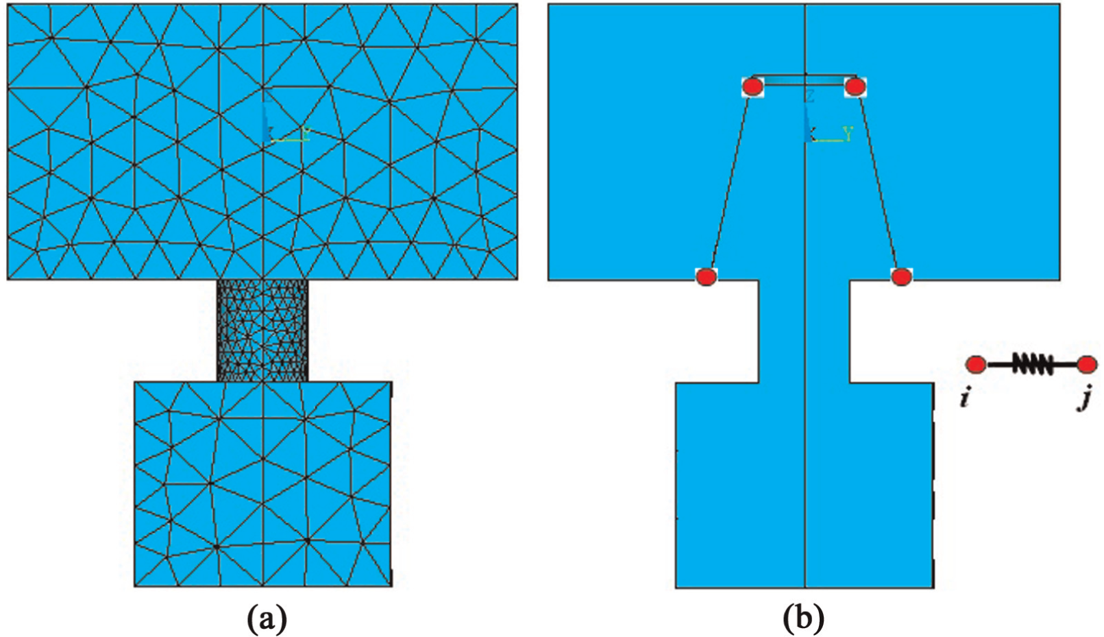
FE model of the specimen: (a) mesh and (b) MATRIX27.
A certain contact stiffness is introduced to the parameter of MATRIX27. Dynamic characteristic of FE model is obtained by utilizing Block Lanczos method. In order to save the calculation time during the parameter identification, an approximate model is proposed in this research. The numerical experiments show that the calculation time of approximate model is only about one-fifth of that of FEM. An approximate model is usually fitted by discrete data. An approximate model based on response surface method was generated from the Taguchi design data in Lee and Song. 21 An approximate model, the variation in nature frequencies of the specimen along with the change in contact stiffness, can be obtained by varying the contact stiffness in a certain range, as plotted in Figure 9. The conclusions can be drawn that the contact stiffness can be identified by the first-order nature frequency when the first-order nature frequency is less than 820 Hz. If the first-order nature frequency is more than 820 Hz, higher order nature frequencies are needed, such as third-order nature frequency. Therefore, it is a multi-objective optimization process. Equivalent error is chosen as the optimization objective. The equivalent error can be represented as
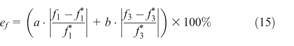
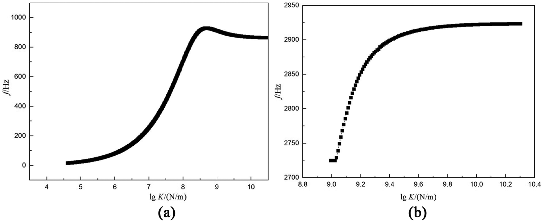
Variation in nature frequencies along with the change in contact stiffness: (a) relationship between contact stiffness and first-order natural frequency and (b) relationship between contact stiffness and third-order natural frequency.
where
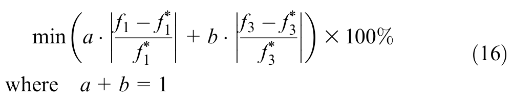
The optimization problem is solved by integration between iSIGHT and the approximate model established in this research. The integration is realized by multi-disciplines optimization language (MDOL). The optimization process is listed as follows. First, the approximate model is obtained by varying the contact stiffness in a certain range by FEM, and the contact stiffness is initially set in the model as well. Second, the solving file need in the analysis is prepared. Third, the solving file and the result file are parsed by iSIGHT. Because of the calculation time, the asynchronous parsing is conducted. The output file is parsed 2s after the key word in the output file is found. The analysis is carried out with the batching type. Natural frequencies are obtained. And then the design variables are set in the software of iSIGHT. The optimization task, in which equivalent error is chosen as the optimization objective, is established. Finally, the optimization is solved by adaptive simulated annealing (ASA) algorithm. The equivalent error is calculated by ANSYS according to the input value of contact stiffness of spindle–tool holder. The input values of contact stiffness for the next calculation are provided according to the equivalent error acquired in the previous calculation by the optimization algorithm on the platform of iSIGHT, and they are written to the corresponding position in the input file. The process will not stop until the equivalent error reaches its minimum in change range of the design variable. Via optimization, the equivalent error reaches its minimum value. In this way, the contact stiffness of spindle–tool holder is identified. Flow chart of the calculation is potted in Figure 10.
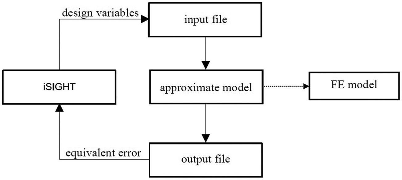
Flow chart of the optimization.
Analysis and comparisons
In the experiment, torque wrench is controlled at the tightening moment of 25 kg cm (2.45 N m). In order to calculate contact stiffness, axial pretightening force should be obtained. According to the research, 22 the relationship between tightening moment and axial pretightening force is

where T is the tightening moment of the bolt;
The specimen is hanged during the test, and therefore, pretension between spindle substructure and tool holder substructure is obtained by axial pretightening force subtracting the gravity of tool holder substructure.
The surface of specimen is formed by turning. According to the machining form, the fractal parameters are estimated. D = 1.4 and G = 0.032 nm 23 are introduced to the fractal theory. Contact pattern is checked on the combine surface by colored marks. Red lead mixed with kerosene is applied to the combine surface. Contact spots are pulled off using clear packing tape. And then contact spots are pasted on a piece of white card. A piece of coordinate article is covered on the contact spot to detect the contact area. The samples are plotted in Figure 11. By the miniating method, the contact ratio is obtained, and its average value is 1%. The contact ratio obtained by fractal theory is 1.1124%. The conclusion can be drawn that numerical value gained by fractal theory is a little greater than the experimental value. The reason is that the area in red is enlarged during the pulling off process. As a result, the experimental value is a little smaller than the theoretical value. But the error between the two results is relatively small. The assumption (D = 1.4, G = 0.032 nm) about the contact pattern on turned surfaces is validated.
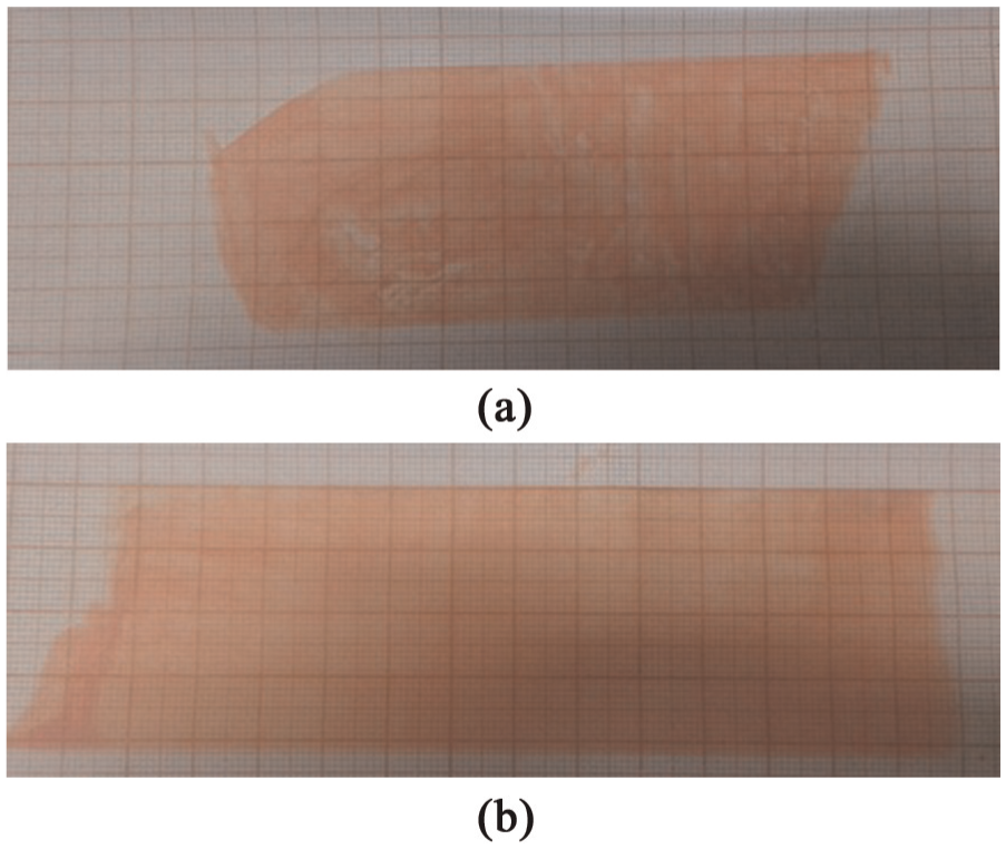
Miniating samples with red remark: (a) Sample A and (b) Sample B.
Fractal parameters are introduced to the theoretical model proposed in this research. The contact stiffness of the spindle–tool holder can be drawn and its value is
Comparison between results obtained by different methods.
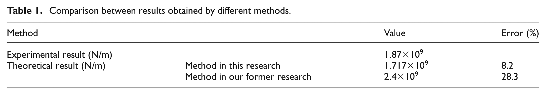
The comparison between theoretical result and experimental result demonstrates that the analytical method combining classic elasticity theory with fractal theory can be implemented to estimate the contact stiffness of the spindle–tool holder. The advantage of this method is that contact stiffness of spindle–tool holder can be obtained by the method on the premise of not making prototypes or using hammer-hitting pulse-inspirit method. Moreover, effects of cutting force can be considered by this method. The method in this article can be implemented to solve the contact stiffness at the spindle–tool holder during the design stage.
The ISO 26623 spindle interface is an innovative modular tooling system with maximum precision and particularly widespread in multi-task machines (turn-mill centers). The torque transmission and centering take place via the polygon-shaped taper with flange surface contact. As a result, a fixed axial positioning and a high degree of torsional rigidity are achieved. For the new modular tooling system, the stress distribution on contact surfaces can be obtained by FEM due to the complex feature of tooling systems. According to the stress, stiffness at each diminutive area can be calculated by fractal theory. On that basis, the stiffness can be integrated on contact surfaces.
Effects of cutting force on contact stiffness of spindle–tool holder
In actual working conditions, existence of cutting force leads to the redistribution of contact stress at the spindle–tool holder interface. In order to study the effect of cutting force on contact stiffness of spindle–tool holder, the variation in contact stiffness of spindle–tool holder along with the change in cutting force is investigated taking CAT40, for example, when rotation speed of the spindle is 8000 r/min, and drawbar forces are 3 and 4 kN, respectively.
From the variation plotted in Figure 12, the conclusion can be drawn that contact stiffness of spindle–tool holder increases along with an increase in the drawbar force and the cutting force. The reason is that the introduction of cutting force changes the distribution of contact stress, and the contact stiffness on diminutive areas also changes. The contribution of the increasing part to whole contact stiffness of spindle–tool holder is more than that of the decreasing part. Relatively large error will be generated if cutting force is ignored in the solving process of contact stiffness of spindle–tool holder. Therefore, it is necessary to consider the effect of cutting force in modeling the contact stiffness of spindle–tool holder.
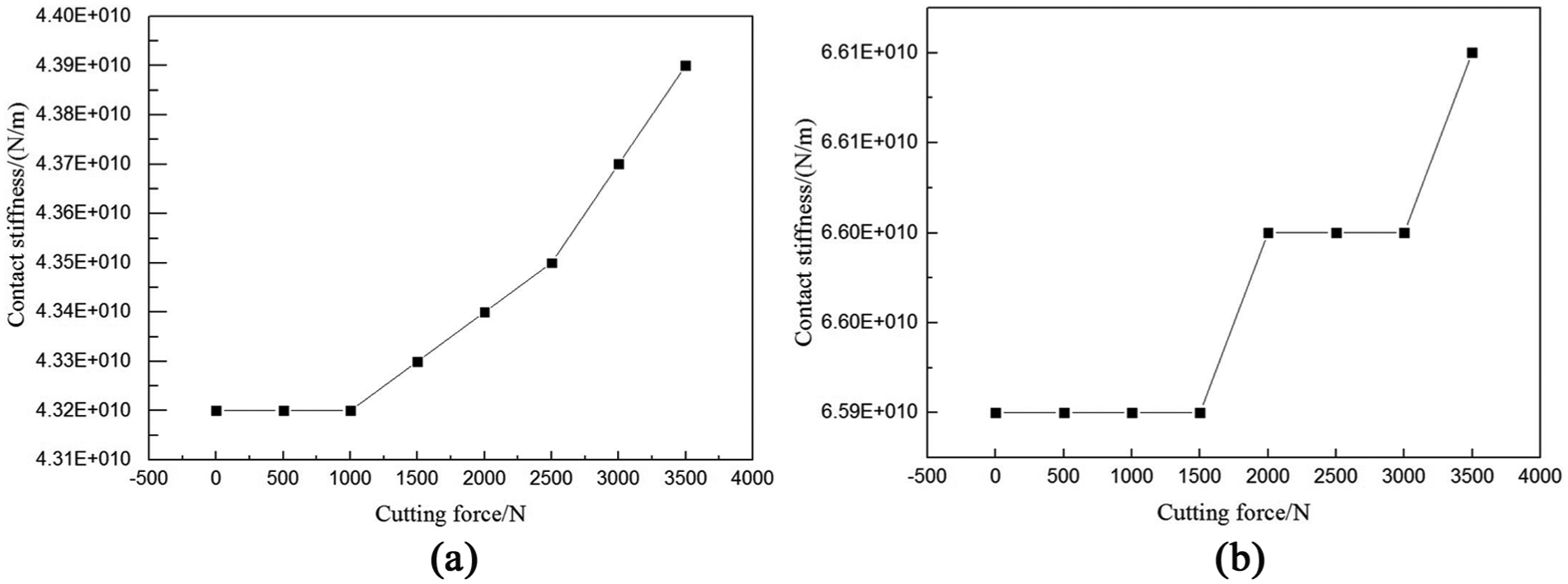
Effects of cutting force on contact stiffness of spindle–tool holder (rotation speed of the spindle is 8000 r/min): (a) drawbar force is 3 kN and (b) drawbar force is 4 kN.
Conclusion
The following conclusions can be drawn from modeling of contact stiffness of spindle–tool holder:
An analytical method combined classic elasticity theory with MB fractal theory is proposed considering the effect of cutting force to estimate contact stiffness of spindle–tool holder in this research. Microscopic fractal characteristics of interfaces can be considered in this method. Contact stiffness of spindle–tool holder can be obtained by the method proposed in this article on the premise of not making prototypes or using hammer-hitting pulse-inspirit method. The calculating model and method in this article can be implemented to solve the contact stiffness at the spindle–tool holder during the design stage.
The effectiveness of the proposed method is validated by the self-designed experiment. In order to save calculation time, an approximate model is proposed to replace FE model in the processing of identification of contact stiffness of spindle–tool holder.
Effects of cutting force on stiffness of spindle–tool holder are investigated in this research. Contact stiffness of spindle–tool holder increases along with increasing the drawbar force and the cutting force. Relatively large error will be generated if cutting force is ignored in the modeling process of contact stiffness of spindle–tool holder.
Footnotes
Acknowledgements
The authors are grateful to other participants of the projects for their cooperation.
Declaration of conflicting interests
The authors declare that there is no conflict of interest.
Funding
This work was supported by National Natural Science Foundation of China, Grant No. 51105010, Natural Science Foundation of Beijing, Grant No. 3122005, KZ201410005010 and 3154029, Important National Science & Technology Specific Projects of China, Grant No. 2012ZX04010021-001-004 and Startup Project of Doctor Scientific Research of Beijing University of Technology.