
Abstract
Cutting force coefficients were conventionally described as the power function of instantaneous uncut chip thickness. However, it was found that the changes in the three controllable machining parameters (cutting speed, feed and axial cutting depth) could significantly affect the values of cutting coefficients. An improved cutting force model was developed in this article based on the experimental investigation of end milling titanium alloy (Ti6Al4V) with polycrystalline diamond tools. The relationships between machining parameters and cutting force are established based on the introduction of the new cutting coefficients. By integrating the effects of varying cutting parameters in the prediction model, cutting forces and the fluctuation of cutting force in each milling cycle were calculated. Validation experiments show that the predicted peak values of cutting forces highly match the experimental results; the accuracy of the model is up to 90% in predicting instantaneous cutting forces.
Introduction
Titanium alloy (Ti6Al4V) is known as a difficult-to-machine material because of its poor thermal conductivity and high cutting force in the conventional milling process. Large cutting forces are detrimental to tool life and surface integrity of workpieces and should be avoided in the machining process. Sun et al. 1 found that the cutting force in normal milling processes was dramatically higher than that of laser-assisted milling process. The cutting force of normal milling process was nearly two times higher than that of a machining system with high oil supply rate. 2
The availability of an accurate cutting force model is essential in predicting cutting forces, which is important in selecting suitable machining parameters. Many approaches have been developed to calculate cutting forces in the past decades. Generally, these approaches can be divided into two categories. The first category is to use finite element method (FEM) to calculate cutting forces. 3 The second category is based on the analytical cutting force model which is suitable for stable-state and variable machining conditions. 4 FEM models are time consuming and are insufficient due to the restriction of constitutive equations of material and machining conditions. In comparison with FEM models, the analytical method developed based on experimental results is more practical.
Many analytical models for the prediction of instantaneous cutting force are based on the calculation of cutting coefficients through the analyses of theoretical chip thickness. Yun and Cho 5 developed a cutting force model which could determine the constant cutting force coefficients and runout parameters in end milling processes. Lee and Lin 6 introduced a three-dimensional (3D) cutting force model for the end milling of freeform surface which incorporated the helix angle of the tool and the variation of instantaneous axial cutting depth. Wang et al. 7 developed an end milling cutting force model by considering the instantaneous vibration, shear plane area and cutter geometries. By analyzing the relationship between cutting forces and chip load, Kline et al. 8 found that the instantaneous uncut chip thickness was the key factor in determining the coefficients, and a cutting force model with the power functions of instantaneous uncut chip thickness was thereafter developed to describe the relationship between feed and cutting force. In studying circular end milling processes, Wu et al. 9 described the cutting coefficients of tangential, radial and axial force components in the polynomial format with a curve fitting method based on experimental results. But their model includes only one single variable—radial depth of cut. According to the results found by other researchers,10–13 the change in machining parameters could cause strain hardening effect or heat softening effect which would further affect the values of cutting forces. However, in these empirical models, the effects of the three machining parameters (e.g. cutting speed, feed and axial cutting depth) have not been reflected.
Polycrystalline diamond (PCD) is a sintered material which combines diamond particles as small as a few micrometers with binding material of cobalt. It has the excellent physical properties of natural diamond of high hardness (7000–11,000 HV) and high thermal conductivity of up to 2000 W/m K. 14 PCD tools used in the machining of Ti6Al4V have shown excellent performance. For example, Nurul Amin et al. 15 found that PCD inserts outperformed WC-Co inserts in the machining of titanium alloys (Ti6Al4V). The tool life of 381 min has been achieved by Kuljanic et al. 16 in milling Ti6Al4V blades with the cutting speed of 110 m/min and feed rate of 0.125 mm. However, little research has been conducted so far to analyze the cutting force in milling Ti6Al4V with PCD tools.
In this article, a new cutting force model was developed based on the analysis of the change of cutting speed, feed and axial cutting depth. The relationships between machining parameters and cutting force are established based on the introduction of the new three cutting coefficients. By integrating the effects of varying cutting parameters in the prediction model, the cutting force and the variation in cutting force in each milling cycle can be calculated with minimized prediction errors. The new model was validated successfully through a series of cutting tests.
Materials and experiment setup
Customized PCD cutting tool and workpiece
The samples of PCD insert and disk and the customized PCD end milling tool of 6 mm in diameter are shown in Figure 1. The helix angle and clearance angle of the tool are 0° and 10°, respectively.
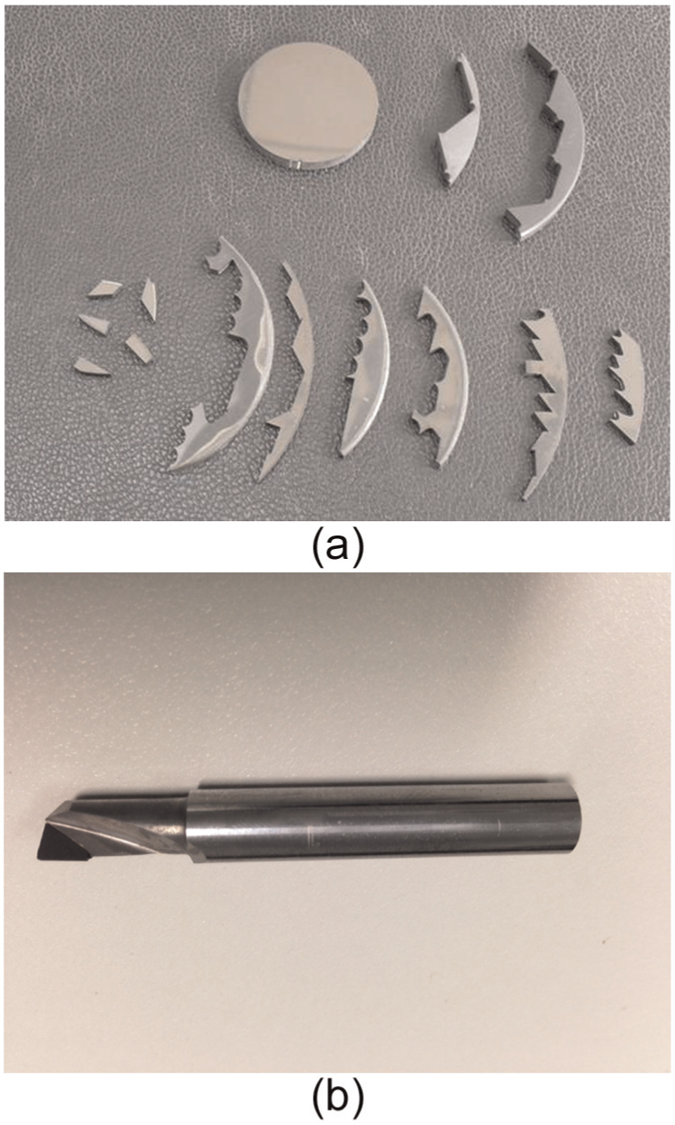
(a) PCD blanks and chips and (b) single-tooth PCD tool.
The fabrication of the PCD tool was carried out in three steps: (a) cut PCD blanks into small inserts; (b) braze the inserts on a carbide substrate; (c) grind and shape the cutting edges into the required dimension and surface finish. Since diamond is the hardest material in the world, the cutting and grinding processes (a) and (c) are very difficult. Wired Electric Discharge Machining (W-EDM) was used to cut small PCD inserts from a large blank (Figure 1(a)), and Electric Discharge Grinding (EDG) was employed to grind the PCD insert brazed on the tool body to produce the desired geometry and surface roughness of the PCD cutting tool. Figure 2(a) shows the scanning electron microscopy (SEM) (Philips XL 30) image of the new PCD tool. It can be seen that tiny notches which are less than 10 µm exist on the edge of the PCD insert.
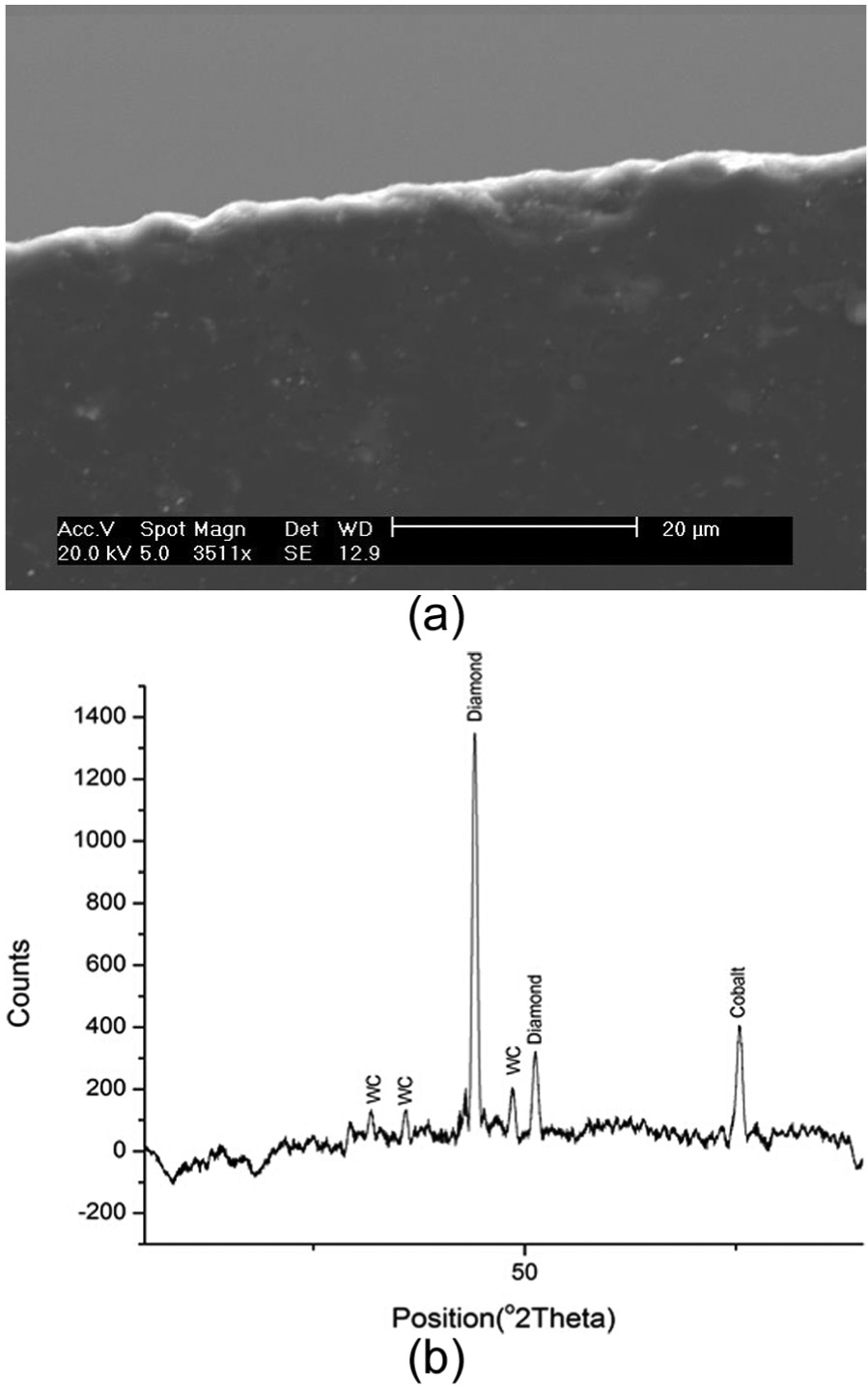
(a) SEM image of the new PCD tool and (b) X-ray diffraction of PCD inserts.
The property of PCD material is known to play an important role in the machining process. Different PCD materials may demonstrate different performance in the milling process due to the difference in particle size and the proportion of diamond particles. The properties of the PCD material used in this research (CTB010 made by Element Six) are shown in Table 1. 11 The chemical components measured with the X-ray diffraction method are illustrated in Figure 2. The vertical axis represents the count rate of chemical element; the horizontal axis represents the exciting energy level of each chemical element. It can be seen in Figure 2(b) that the majority of the chemical components in PCD are diamond; only a small amount are cobalt and tungsten carbide which comes from the substrate. This type of PCD material is suitable for applications of super-finishing, finishing and general-purpose machining.
Properties of PCD.
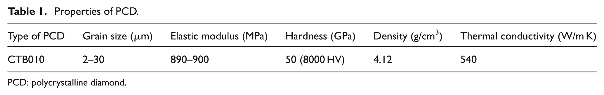
PCD: polycrystalline diamond.
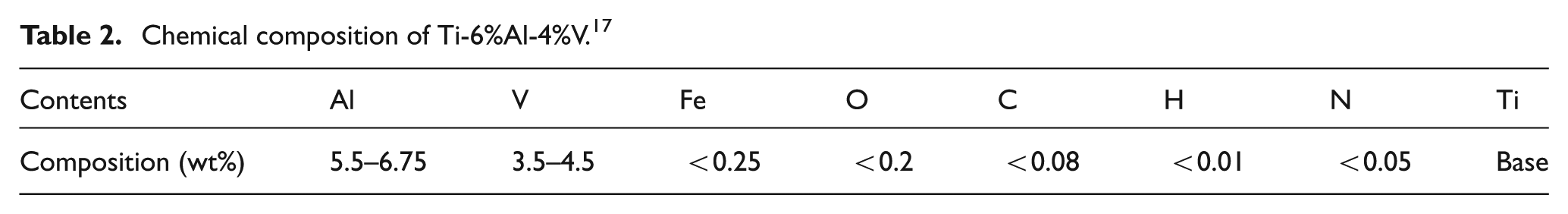
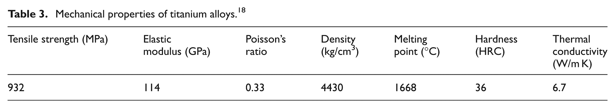
The material of the workpiece is Ti-6%Al-4%V (Ti6Al4V). This is an “Alpha + Beta” type of titanium alloy. It is widely used in aerospace industry and has demonstrated superior overall performance. Four blocks of such material were used in the experiments. The chemical composition and mechanical properties of Ti6Al4V are illustrated in Tables 2 and 3, respectively.
Chemical composition of Ti-6%Al-4%V. 17
Mechanical properties of titanium alloys. 18
Experimental setup
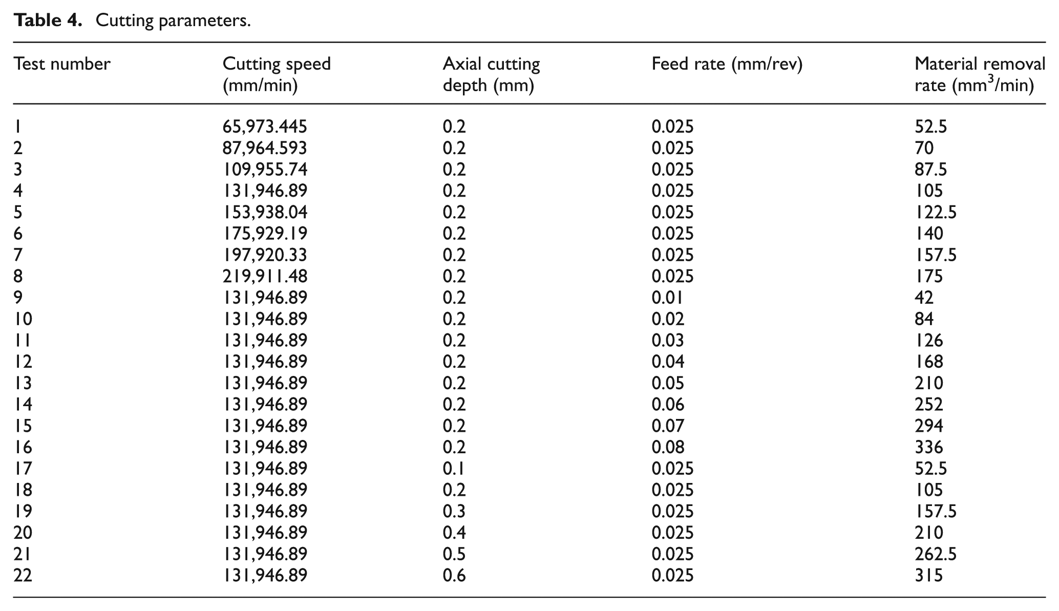
A total of 22 cutting experiments were carried out on a four-axis HAAS milling machine. The signal of cutting force was collected through a six-channel dynamometer (Kistler 9257B) installed underneath the workpiece. The model of coupler was Kistler Multiple Charge Amplifier 5070. The force signal was recorded via a data acquisition (DAQ) (National Instrument model 6036E) card. The setup of the experimental system is illustrated in Figure 3. To simplify the analysis, the tool paths applied in the cutting tests were straight lines along the edge of the workpiece. The machining parameters were listed in Table 4, and the radial cutting depth was 3.5 mm. A conventional flooding coolant was used to decrease the cutting temperature.
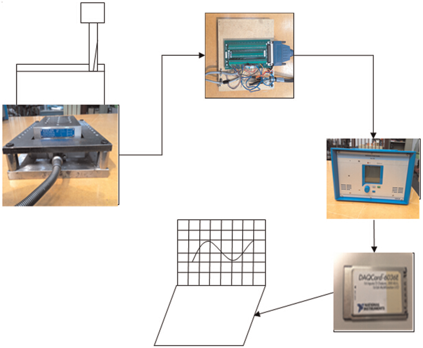
Experimental system setup.
Cutting parameters.
Modeling of cutting force
The instantaneous cutting force
The cutting force components FR, FT and FZ in the local coordination system are shown in Figure 4. FX and FY are the force components in the machine coordinate system.
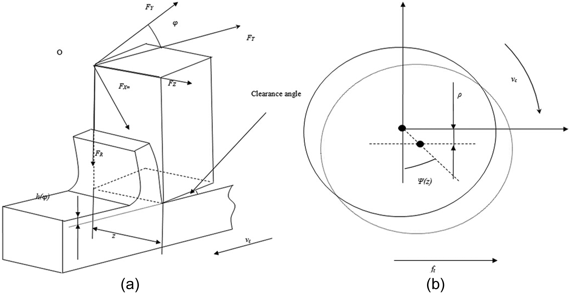
The illustration of cutting force: (a) cutting force components and (b) the run out of cutting tool.
Generally, the three components of the cutting force in the local coordinate system (Figure 4) can be described with the following equation
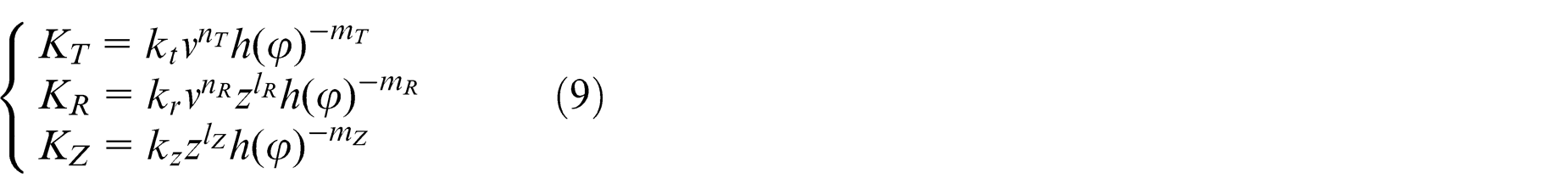
where h(φ) is the instantaneous uncut chip thickness and z is the axial length of each discrete layer. KT, KR and KZ are the cutting coefficients of the three force components and can be expressed as follows 10

where kq and mq (q = T, R, Z) are the parameters relevant to the properties of the workpiece material. By substituting equation (2) into equation (1), the relationship between the uncut chip thickness and the components of local force can be written with equation (3)
Figure 4(b) illustrates the runout effect of the milling process. Due to the vibration, the theoretical chip thickness will either increase or decrease. According to Kline et al., 8 the presence of runout increases the average chip thickness for the teeth actually engaged in the cut and increases the ratio of the maximum to the average force. It also shifts the frequency of the force signal away from the tooth passing frequency to the spindle rotational frequency. Considering the runout effect of the cutting tool, the uncut chip thickness h(φ) can be described as follows

where m is the parameter corresponding to the runout effect of milling process and ξ describes the influence of actual cutting radial on instantaneous uncut chip thickness
where ρ is the parameter which represents the runout error.
Since the flute of the PCD tool used in our experiment was 1, according to Wan et al., 10 the instantaneous uncut chip thickness will not be affected by the runout effect. As such, the coefficients m and ξ will be defined as 1 and 0, and the instantaneous uncut chip thickness can be described as follows

The measuring coordinate system is shown in Figure 4(a). The tangential force (FT), radial force (FR) and axial force (FZ) can be written in the matrix form as [F]T,R,Z. The local cutting force matrix [F]T,R,Z can be obtained by multiplying the transformation matrix [T] by the cutting force matrix [F]X,Y,Z

where the matrix [T] is expressed as follows
Influence of machining parameters
By substituting machining parameters and corresponding cutting forces in each test into equations (1) and (6), the cutting force coefficients of the same rotation angle which equals 18°, as illustrated in Figure 5, can be obtained. These coefficients are only relevant to the instantaneous uncut chip thickness which is the function of feed and instantaneous rotation angle. However, according to the calculation results shown in Figure 5(a) and (c), the change in cutting speed and axial cutting depth could cause dramatic variation in cutting force coefficients. In Figure 5(a), the cutting coefficients KT and KR increase with the increase in cutting speed, while there is less change in Kz when cutting speed changes. As shown in Figure 5(b), the three cutting coefficients drop with the increase in feed rate. Figure 5(c) shows that the coefficients KR and KZ drop with the increase in axial cutting depth and KT remains nearly constant. Therefore, it can be concluded that the change in feed has significant influence on the three cutting coefficients (Figure 5(b)). The change in cutting speed can only affect the cutting coefficients KT and KR. Because the relationship between the cutting speed and cutting coefficient is nonlinear, as illustrated in Figure 5(a), the curves of KT and KR indicate that an exponential relationship exist between the two coefficients and the cutting speed. As shown in Figure 5(c), the change in axial cutting depth significantly influences all the cutting coefficients with an exception of KT. It can be assumed that an exponential relationship exists between KR, KZ and axial cutting depth.
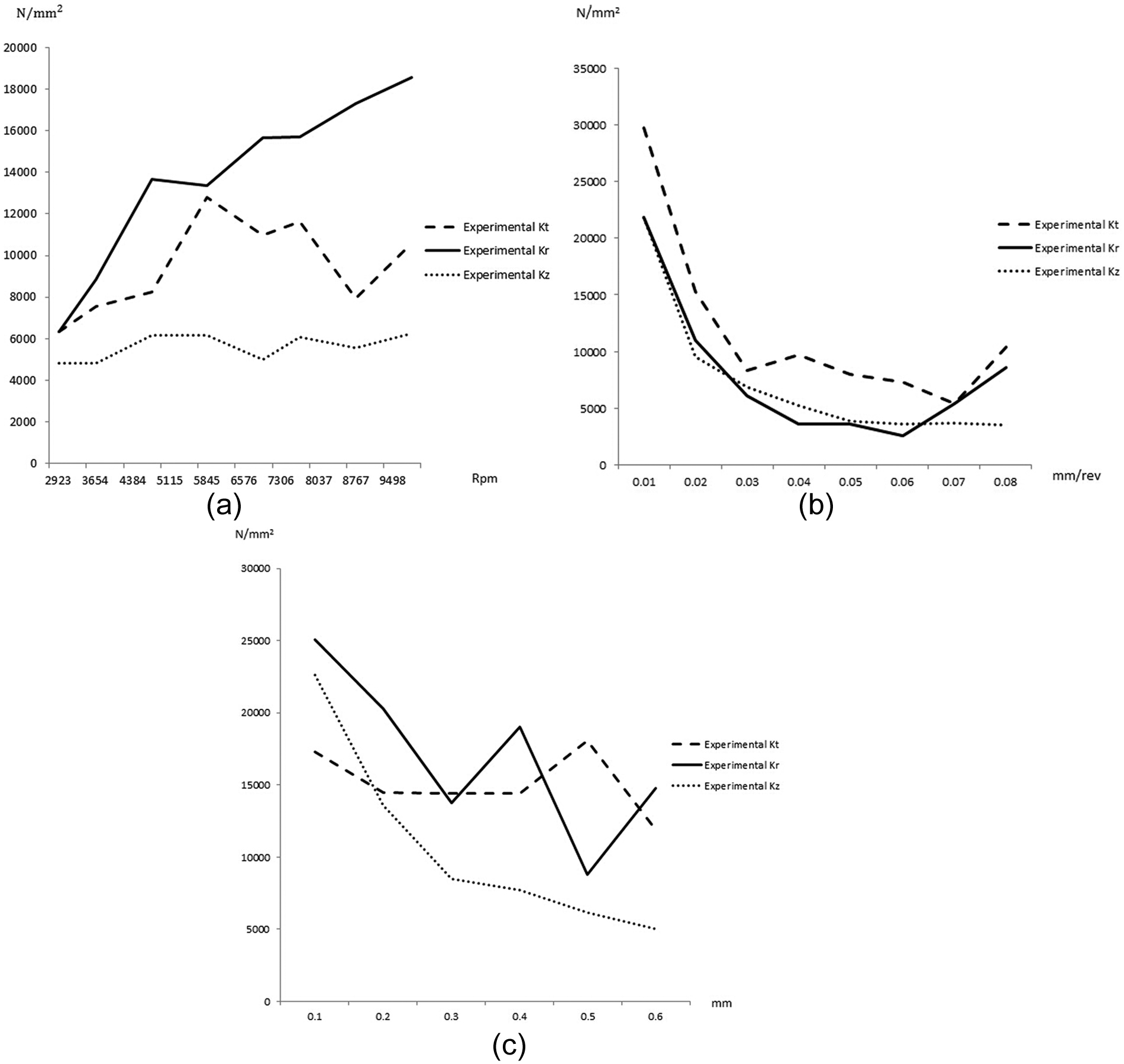
The calculation of cutting coefficient under different machining conditions: (a) effect of cutting speed, (b) effect of feed rate and (c) effect of cutting depth.
Based on the above conclusion and experimental results, the cutting coefficients can be described more accurately as follows
The cutting constants kt, kr, kz, lR, lZ, nT, nR, mT, mR and mZ can be calculated in three steps:
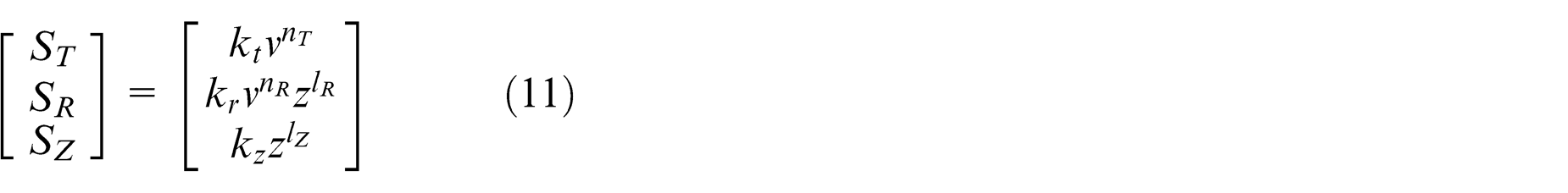
Determine constants mT, mR and mZ. In Tests 9–16, which were to investigate the effects of feed rate while cutting speed and axial cutting depth were constant. The calculation matrix of the three constants can be derived with equation (10). According to the expressions of ST, SR and SZ, although the rest of constants are still unknown, their values will not change because the values of cutting speed and axial cutting depth are constant. Therefore, by substituting the data of Figure 5(b) and corresponding feed into equation (10), the final values of mT, mR and mZ can be calculated with the Levenberg–Marquardt method
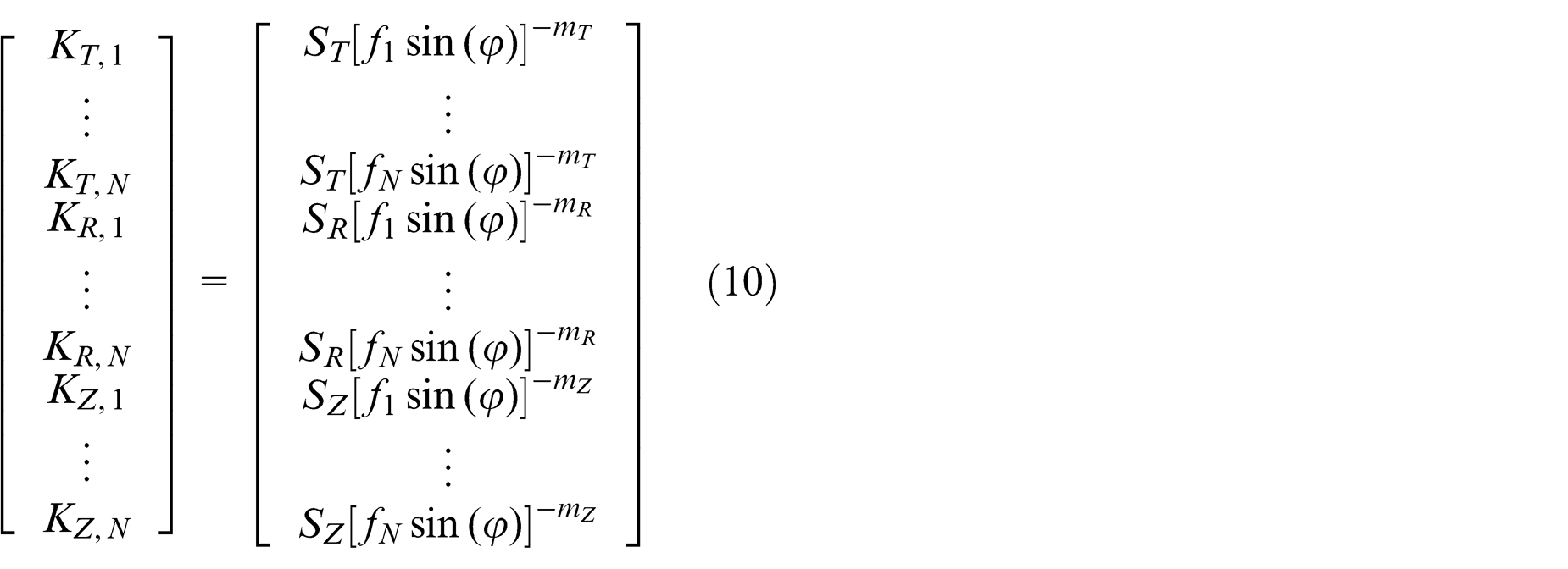
where ST, SR and SZ are as follows
Determine constants kt, kz, nT and lZ. Based on the calculation in Step 1, equation (12) can be derived from equation (9). To calculate the constants kt and nT, the cutting coefficients KN (N = 0, 1, …, 8; N ≥ 2) and machining parameters of Tests 1–8 were used. Similarly, the cutting coefficients KN (N = 0, 1, …, 6, N ≥ 2) and machining parameters of Tests 17–22 were used in calculating kz and lZ. The rotation angles which were used to calculate cutting coefficients were the same, and the feed rates of Tests 1–8 and Tests 17–22 were 0.025 and 0.03 mm/rev, respectively. Therefore, the values of FT and FZ should be constant in the calculation
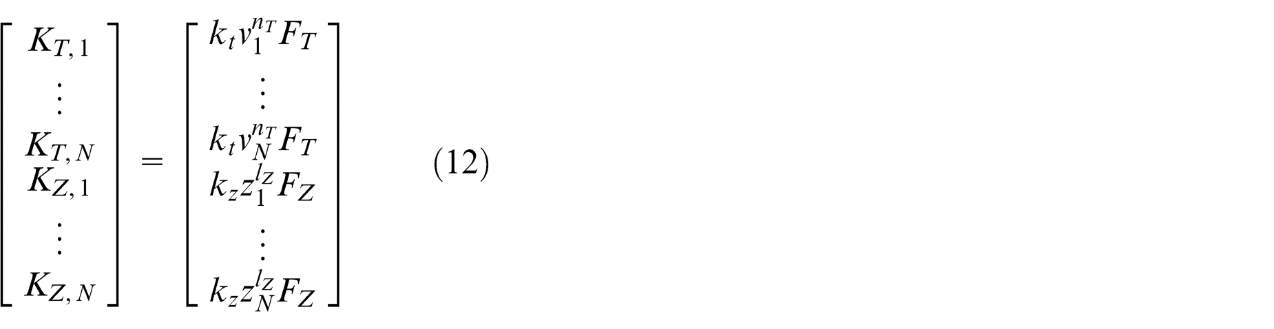
where

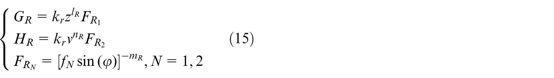
Determine constants kr, nR and lR. Figure 5 indicates that the value of KR is affected by cutting force, feed and axial cutting depth. And the relationship between this coefficient and the three machining parameters is exponential. First, to calculate the constant nR, the cutting coefficients of Tests 1–8 and the corresponding cutting speeds were substituted into equation (14). Then, by using the same method, the constant lR was calculated with the cutting coefficients of Tests 17–22 and corresponding cutting speeds. Finally, the last constant kr could be obtained based on the calculation in Step 2
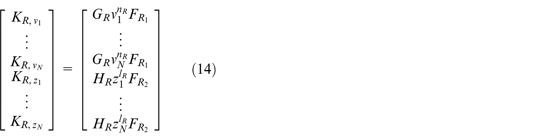
where
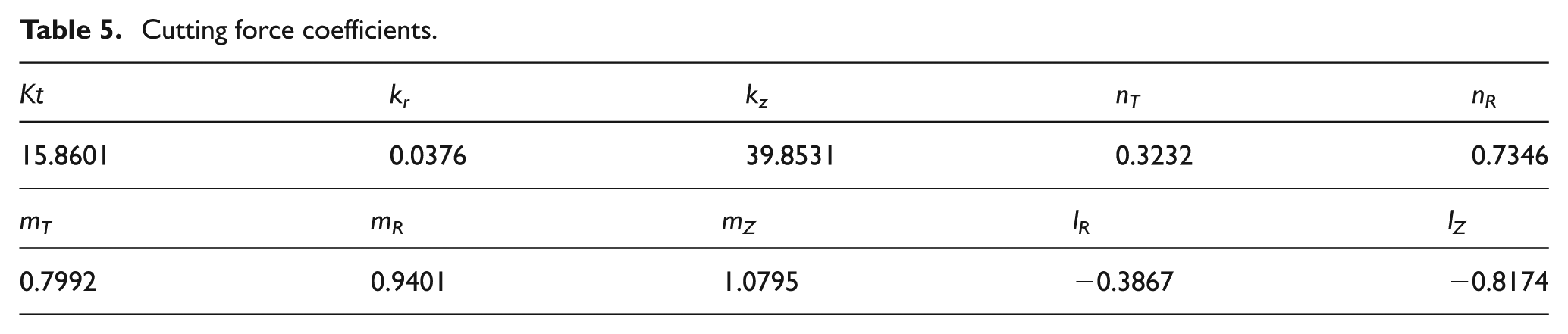
By applying the experimental cutting forces and corresponding machining parameters, the cutting coefficients were calculated and the results are listed in Table 5.
Cutting force coefficients.
Comparison of simulation and experimental results
Figure 6 shows the relationship between the average cutting force and the three machining parameters. It was calculated by substituting the cutting force coefficients given in Table 5 into the cutting force model. To simplify the analysis, the average resultant forces of each milling cycle were calculated with equation (16). The experimental values of FT, FR and FZ were calculated with equation (7) and the predicted results of these three values could be obtained from the cutting force model with cutting force constants listed in Table 5. As shown in Figure 6, the simulation results highly match the experimental results

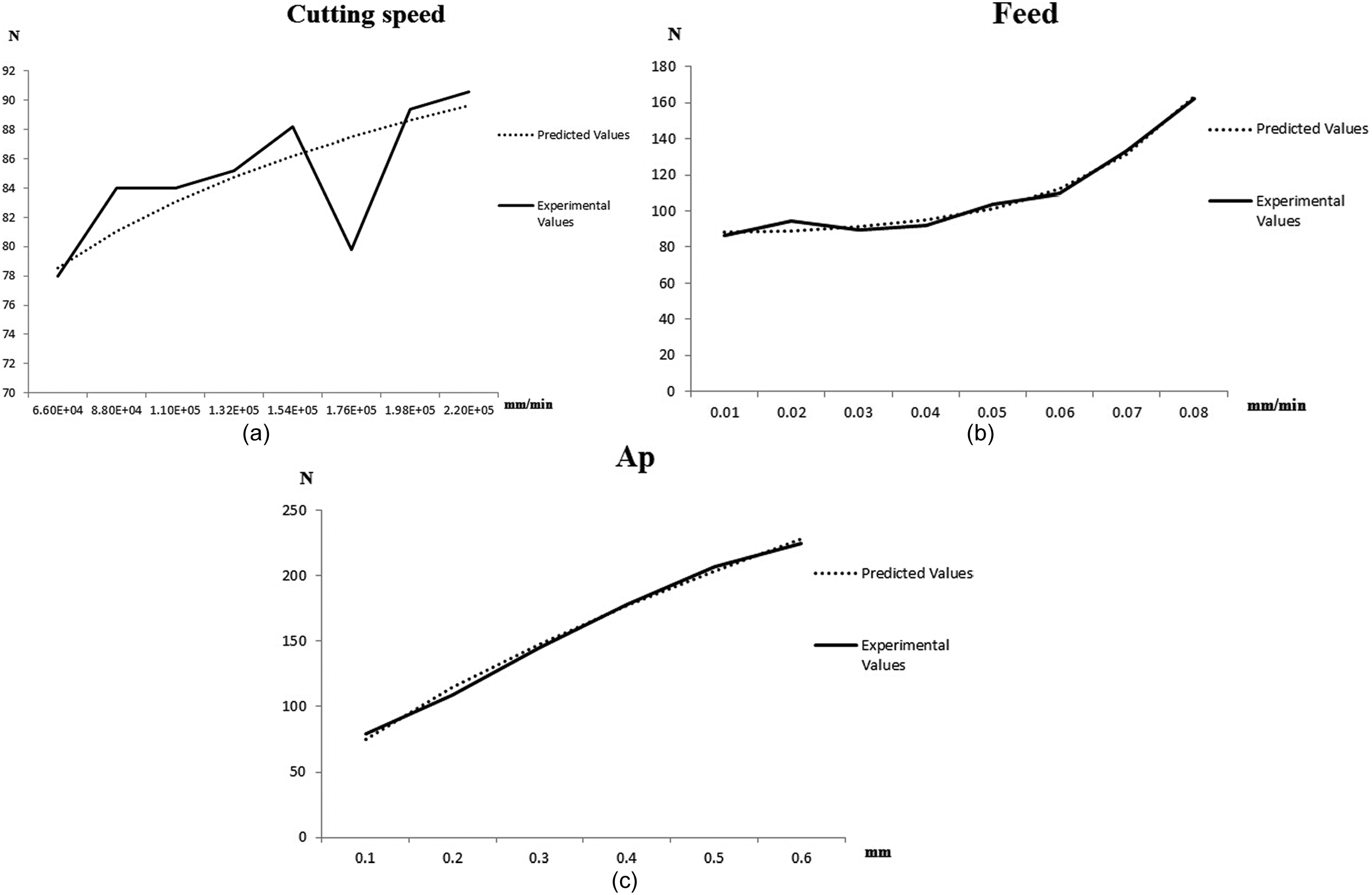
Influence of machining parameters on cutting force: (a) the relationship between instantaneous cutting force and cutting speed, (b) the relationship between instantaneous cutting force and feed rate and (c) the relationship of instantaneous cutting force and axial cutting depth (Ap).
It is known that the change in machining parameters would directly affect the instantaneous cutting force. For example, in high-speed milling of Ti6Al4V alloy with PCD tools, it was found that the cutting force dropped when the cutting speed was increased. 19 The cause led to such phenomenon was that the low thermal conductivity and the insufficient heat dissipation resulted in the rise of regional cutting temperature when the cutting speed was increased. The softening effect finally caused the drop of cutting force.
However, the situation is quite different in this study. By applying the PCD tool in milling Ti6Al4V with the conventional cutting speed which is in the range between 65 and 220 m/min, the cutting force increased with the increase in cutting speed as shown in Figure 6(a), rather than decrease as in other studies.
In Figure 6(a), the overall trend was that the cutting force increased with cutting speed, and the experimental data matched predicted data perfectly. However, it can be found that the cutting force dropped when the cutting speed increased to 175,929.19 mm/min, which was the case of Test 6. The predicted cutting force in Test 6 was 86 N; however, according to the experimental result, actually the average cutting force measured in Test 6 was around 79.5 N, which was 6.5 N lower than the predicted value. This abnormal difference was caused by the tool failure occurred in Test 6. After two continuous cutting tests, the cutting edge of the PCD tool was seriously damaged. Due to the high cutting speed, the friction between the worn-out tool and the workpiece generated huge amount of cutting heat, which in turn softened the workpiece material. Just as being analyzed by Sun et al., 1 the softening effort led to the drop of cutting force. It can also be seen in Figure 6(a) that once the damaged tool was replaced with a new one in Test 7 (cutting speed increased to 197,920.33 mm/min), the abnormal phenomenon disappeared and the actual cutting force became normal.
As shown in Figure 6(b), the cutting force increases exponentially with the increase in feed rate when the cutting speed and axial cutting depth were constant. In Figure 6(c), in contrast to the experimental result of feed, the increasing speed of cutting force slowed down constantly.
The instantaneous cutting force
Figure 7 shows the instantaneous cutting force in a single milling cycle. It can be seen that the maximum cutting force occurred when the cutting angle was in the range of 15°–20° in most of the experiments, and the maximum peak was followed by a significant drop in cutting force before next small peak occurred. As compared with the current cutting force models,20,21 in which the fluctuation of cutting force in each milling cycle was usually neglected, this model predicted the cutting force more accurately.
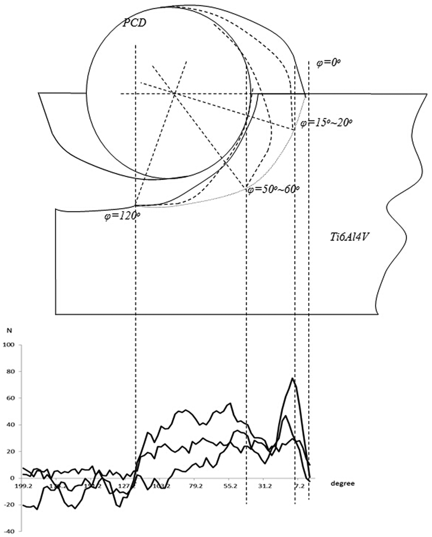
Illustration of tool rotation and the corresponding instantaneous cutting force.
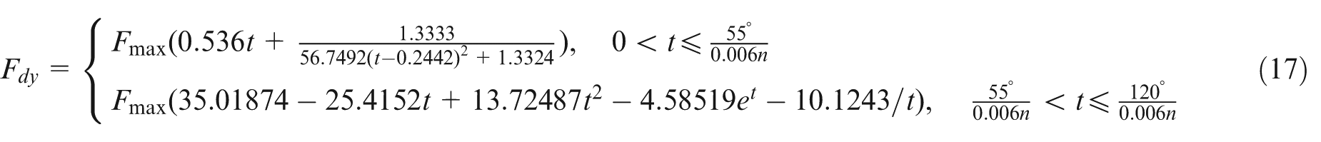
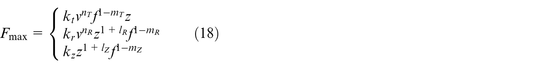
An improved equation (equation (17)) was developed by applying the Levenberg–Marquardt method. This equation describes the evolution of instantaneous cutting force with the elapse of time.
In equation (8), Fmax equals the peak cutting force which can be calculated by the model introduced in section “The instantaneous cutting force.” Time (t) is the only variable in the function, t = (ψr/v), where ψ is the cutting angle of the tool. The exit angle of each cutting cycle was around 120°. According to experimental results, the significant fluctuation of instantaneous cutting force stops when the cutting angle was 50°.
Figure 8 illustrates the two-step flow chart for the prediction of instantaneous cutting force: Step 1 is to determinate the cutting parameters with the method introduced in sections “The instantaneous cutting force” and “Influence of machining parameters”; Step 2 is to calculate the peak value of cutting force with the corresponding machining parameters and to calculate the instantaneous cutting force with equation (17) iteratively.
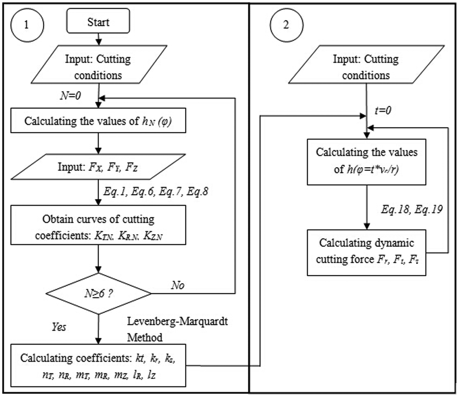
Flow chart of calculating instantaneous cutting force.
Figure 9 shows the predicted and real instantaneous cutting forces in Tests 6 and 8, respectively. The predicted tangential, radial and axial cutting forces highly match the experimental results. The accuracy of this model is up to 90%. It can be seen that the maximum error in prediction (the difference between the predicted and real peak values) is less than 3.5 N
where
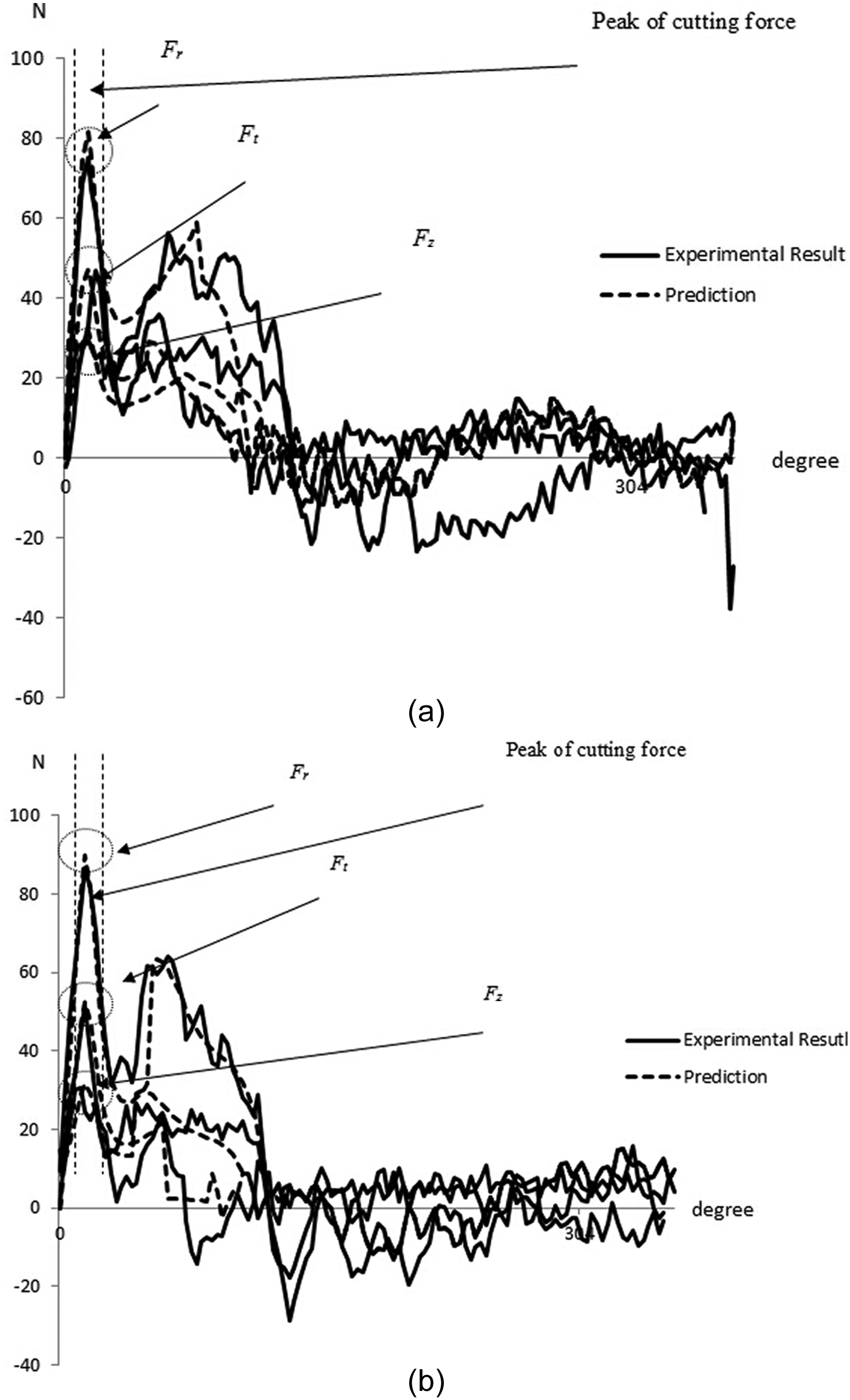
The instantaneous cutting force curves: (a) Test 6 and (b) Test 8.
Conclusions
A new cutting force model was developed based on the varying machining parameters for the prediction of cutting forces in milling Ti6Al4V with customized PCD tools. A new method which is adaptive to a wide range of machining parameters was introduced to improve the accuracy in calculating cutting force coefficients.
The changes in machining parameters could affect not only the cutting force, but also the cutting force coefficient. Experimental results showed that fluctuations existed in each milling cycle. To predict the instantaneous cutting force more accurately, a time-dependent cutting force model has also been developed. Validation was conducted through cutting tests with single-flute PCD end mills. The maximum predictive error of the peaks of cutting forces was found to be less than 3.5 N.
Footnotes
Appendix 1
Declaration of conflicting interests
The authors declare that there is no conflict of interest.
Funding
This research received no specific grant from any funding agency in the public, commercial or not-for-profit sectors.