
Abstract
An integrated mathematical model was developed to study the thermo-mechanical behavior of strips and work-rolls during warm rolling process of steels. A two-dimensional finite element analysis was first employed to solve for the thermo-mechanical response of the rolled strip under steady-state conditions. The calculated roll pressure and temperature fields were then used to apply proper boundary conditions for solving the governing thermo-mechanical problem for the work-roll. The obtained results indicate that in warm strip rolling of steels, the thermal and mechanical stresses developed within the work-roll are comparable; however, the more significant influence is due to heating and cooling of the work-roll during the process, particularly in case of warm rolling operations of the strips with higher initial temperature. Besides, the utilized model was shown to be capable of determining the effects of various rolling parameters on the thermo-mechanical behavior of strips and work-rolls during warm rolling process.
Introduction
Being the most prominent among all metal forming operations, rolling has received extensive consideration for the past decades. During recent years, modeling and simulation of this process along with the prediction of the rolled products properties have been extensively conducted with special attention drawn toward the use of finite element (FE) analyses. 1 FE studies have mostly been performed in order to investigate the deformation and thermal behavior of strips and rolling mills in hot and cold rolling processes. For instance, elastic–plastic modeling of the deformation behavior of the strip during cold rolling process has been performed by Liu et al. 2 Steady-state modeling of cold rolling was studied by Prakash et al. 3 Pressure distribution along the contact area was determined in this work for the case of work-hardenable strips. Stress fields developed within the work-roll during cold rolling have been examined in a few works. Using rigid plastic behavior for the strip, Gratacos et al. 4 applied the calculated rolling pressure as the boundary condition to examine the deformation of rolling mills. Arif et al. 5 investigated the thermo-mechanical behavior of work-rolls during cold strip rolling. It was shown that the temperature rise taken place within the roll material can influence the stress field developed in the cold rolling mills. FE modeling of the deformation gap in steady-state cold rolling process of steel strips was also performed by Koohbor and Serajzadeh. 6 It was shown in this work that the temperature field developed within the rolled strip, as well as the rolling mill, may experience significant changes when the magnitude of the thickness reduction exceeds a certain value.
In addition to cold rolling, warm and hot rolling processes have also gained great attention in several works. Attention in warm and hot rolling processes has mostly been toward the prediction of temperature, strain and strain rate distributions in the rolled material, as these variables control the final microstructure and mechanical properties of the rolled product.7–9 For instance, Wang et al. 10 have considered temperature and strain fields in the strip, during hot rolling of low-carbon steels, and studied the microstructural developments which occurred during the process. Moreover, temperature variations and thermal stresses of the work-roll during high-temperature rolling operations have been studied in a few works.11–16 Galantucci and Tricarico 13 examined the strip and work-roll temperature variations during warm rolling process and found that a 350 °C temperature rise may occur in the rolling mills, significantly influencing the stress field and life of the work-roll. Developed thermal stresses in the work-rolls as a result of temperature rise in hot rolling have also been investigated by Chang 14 and Fischer et al. 15 In a similar work, Sun et al. 16 studied the thermo-mechanical loading of rolling mills during hot strip rolling, using a steady-state FE model. It was concluded that the utilized modeling approach could provide a proper and relatively accurate means for the purpose of work-roll life estimation during hot rolling of steels. A very important aspect in the investigation of the thermal behavior of rolling mills in high-temperature rolling practice is the cooling layout and its efficiency during the process. This aspect is considered as an essential factor in life estimation of hot rolling mills, since repeated heating and cooling cycles result in thermal fatigue, significantly influencing the roll life. 16 An interesting study on this particular subject is the work conducted by Tseng et al., 17 in which a combination of experimental and numerical findings has been taken into account to study the thermal behavior of rolling mills in hot and cold rolling operations. In a more recent study, Yadav et al. 18 utilized a coupled FE/analytical solution method to compute the temperature field developed within the work-rolls in hot rolling process with acceptable accuracy.
Warm rolling process has recently been considered as an efficient means to produce flat steel products due to its considerable cost savings as well as desired product properties.19–22 One of the significant aspects in the analysis of this metal forming process is that both mechanical and thermal loadings control the deformation behavior of work-rolls; thus, the use of a coupled thermal–mechanical investigation seems interesting in the study of this particular industrial process. Owing to the importance of warm rolling operations in industry and the fact that very few investigations have been dedicated to the study of the thermo-mechanical behavior of rolling mills in this process, 23 the present work was conducted with the purpose of examining the thermal and mechanical behaviors of work-rolls in warm strip rolling. To do this, a two-dimensional FE model was utilized to obtain the temperature and velocity fields within the strip. Based on the temperature and rolling loads obtained, proper boundary conditions were applied to solve the governing equations for the work-roll. Accordingly, the effects of thermal and mechanical loadings on the deformation behavior of work-roll were determined. The results of such modeling can be utilized in the design of roll-pass schedules as well as roll-type selection, particularly in the case of high-temperature rolling processes with lower strip initial temperature and/or final finishing stands of hot strip rolling, in which longer strip-to-roll contact time and higher strip velocities are present.
Model explanation
The mathematical modeling of the problem in the present work is composed of two separate analyses. In the first part, steady-state thermo-mechanical behavior of the strip was formulated in the deformation zone. Then, the stress distribution as well as the temperature rise on the strip–roll interface area was used as boundary conditions for solving the thermo-mechanical equations on the work-roll.
Mechanical model
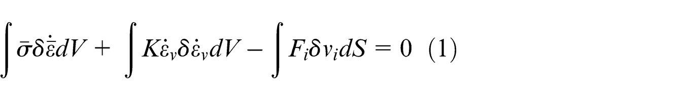
A plane-strain FE model was used to evaluate the mechanical response of the strip in the deformation zone, assuming a rigid visco-plastic material behavior for the rolled strip. The velocity distribution within the deformation zone can be computed based on the following minimization 24
where
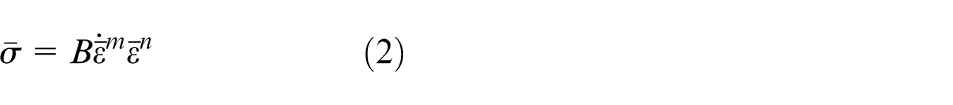
where
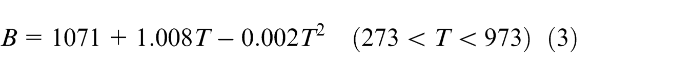
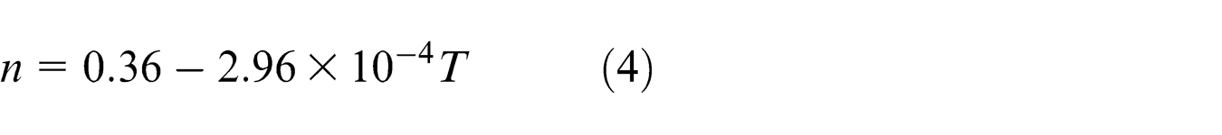
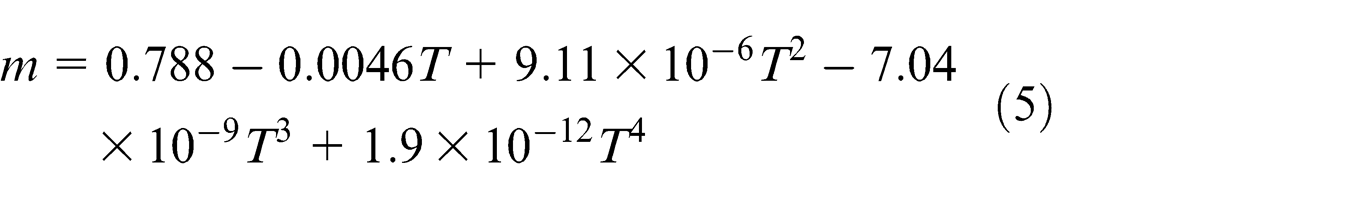
The unit of T in equations (3)–(5) is Kelvin. Note that these temperature-dependent variables were determined in previous works for a low-carbon steel containing 0.048C-0.40Mn-0.04Si-0.02S-0.05Cr (wt%), deformed in the range of 550 °C–700 °C, and were shown to be able to predict the flow behavior of the examined steel with acceptable accuracy. 7
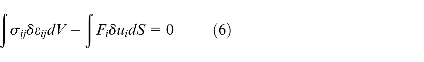
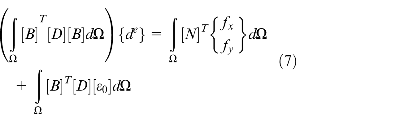
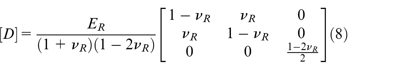
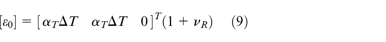
Mechanical behavior of the work-roll was modeled using the stress field obtained within the strip. The obtained load distribution was utilized as the mechanical boundary condition for solving the energy function within the work-roll. Assuming a linear elastic material response for the work-roll, the following energy functional for an elastic body can be considered for the work-roll as 26
With
Note that the effect of backup roll on the deformation behavior of the work-roll was also studied in the present work. To do so, mechanical boundary condition of
Thermal analysis
Calculation of the temperature field within the deforming material was performed using the streamline upwind Petrov–Galerkin (SUPG) scheme. 27 In this method, an additional term of virtual convection is introduced to the heat transfer equation, so that the stability of the calculations is guaranteed. 27 Temperature distribution within the strip is calculated by solving the governing heat transfer equation for the steady-state condition as
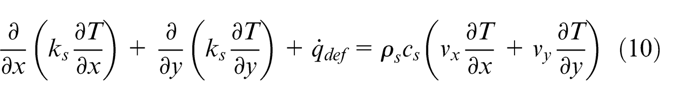
In this equation,
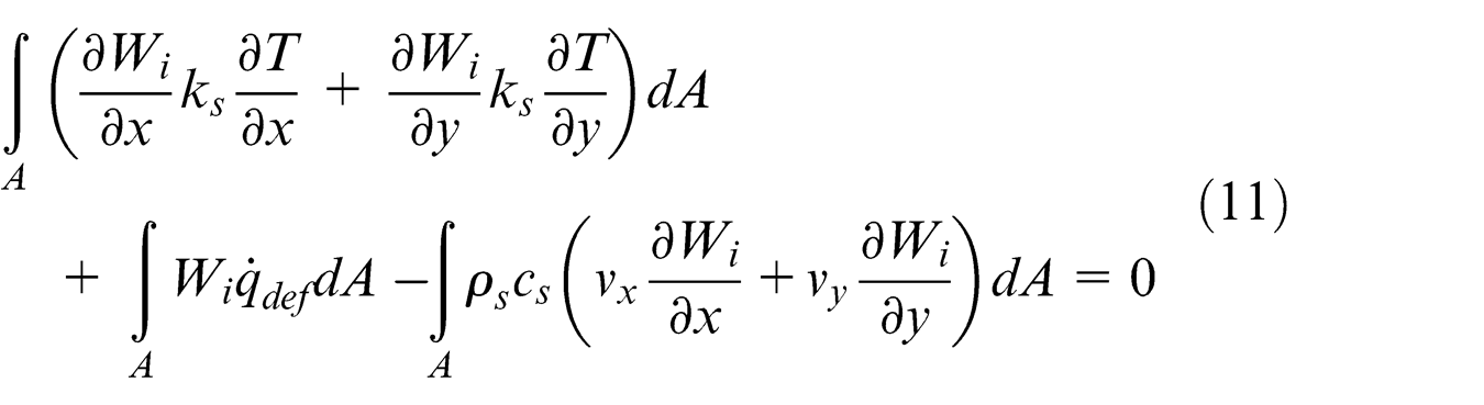
where Wi is the weighting function, determined for SUPG modeling approach based on the following equation 28
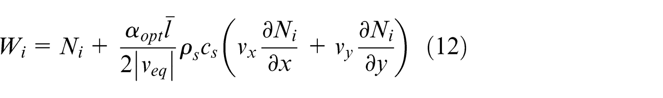
where Ni
represents the shape functions,
26
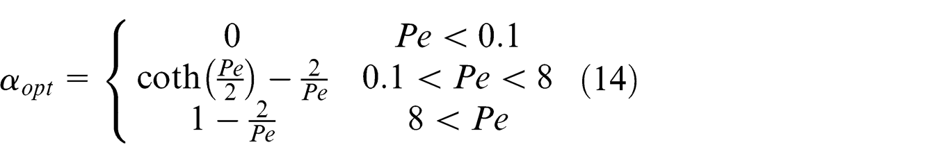
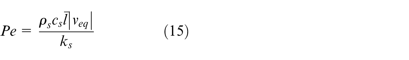
In equation (14), Pe is the Peclet Number, defined as 27
Heat can also be generated at the contact area of metal and work-rolls due to frictional stress. This type of heat source (
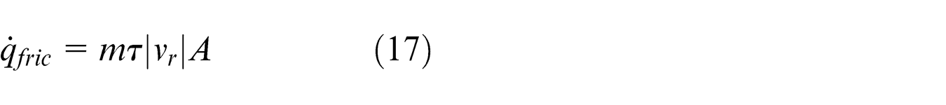
where m is the sticking friction coefficient,
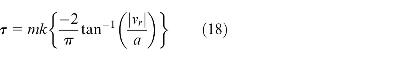
In the above equation, k is the shear yield stress of the strip material, and a is a positive constant of the order 10−3–10−4, according to Kobayashi et al. 24 It should be noted that the sticking friction coefficient in this work was taken to be 0.45, 7 which was shown to be a rather reasonable value in high-temperature rolling operations. 1
In order to express the boundary conditions within the rolled strip, the following conditions were considered:
A constant initial temperature,
Due to symmetry, the center line (symmetry line) of the strip was assumed to be insulated in y-direction, that is, heat flows neither into nor out of this region in y-direction.
The strip travels at relatively high speed in the roll gap; thus, heat conduction along x-direction on the exit zone is neglected when compared to heat transfer in the y-direction; 8 hence, an insulating condition on the exit edge of the strip was applied as well.
Heat is transferred from strip surface to the work-roll within the deformation zone. This condition is described as
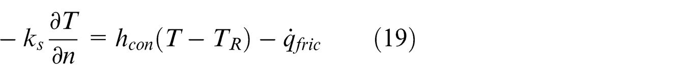
In this equation,
The FE discretization of the strip in the deformation zone was conducted using 30 elements in rolling direction and 20 in half thickness, and the element type was chosen to be three-node linear elements. Following the geometric symmetry of the model, only the upper half section of the strip was meshed and the mechanical boundary condition
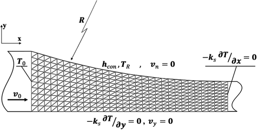
Meshing system and the applied boundary conditions used to model the rolling strip in the deformation zone.
In order to calculate the temperature field in the work-roll, the governing thermal equation was considered as
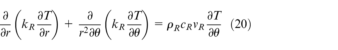
In this equation, subscript R represents the physical constant for the work-roll material, and
Various boundary conditions were applied to solve the thermal equation within the work-roll material:
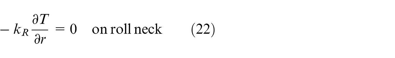
Internal radius of the roll, that is, roll neck, was assumed to be insulated; thus, no heat may transfer into or out of this region
An input heat flux is imposed into the work-roll along the roll–strip interface

where
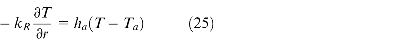
Two regions of water spray cooling are present on the roll surface on which the following boundary condition is dominant
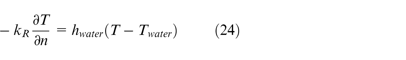
Here,
Work-roll is exposed to the surrounding air, where no contact to strip and/or sprayed water cooling regions exist
The effect of backup roll on the thermal behavior of the work-roll was also examined using the following boundary condition on the upper most elements of the work-roll
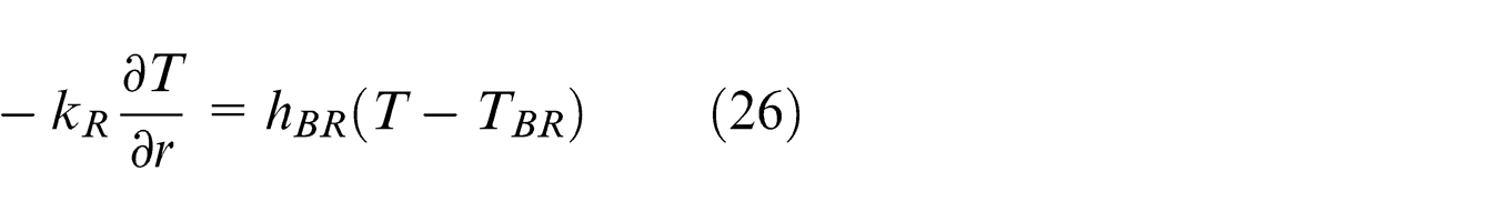
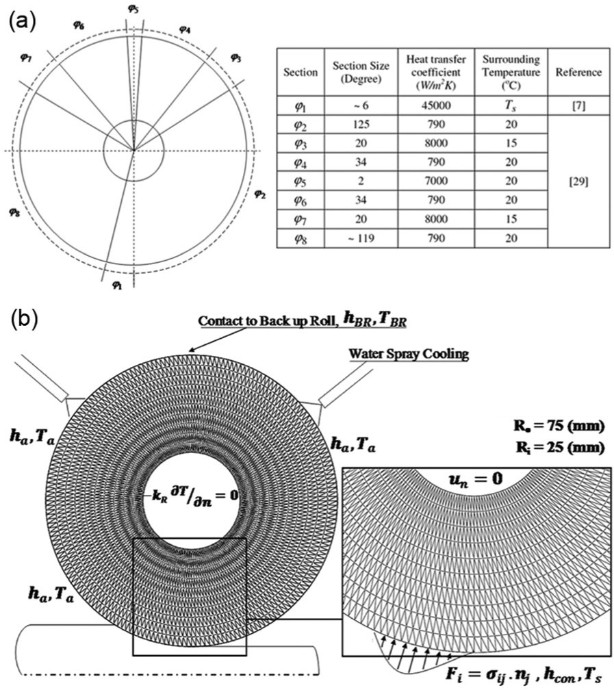
(a) Schematic view of the cooling layout used to formulate the thermal behavior of the work-roll and (b) meshing system and boundary conditions used for FE modeling of the work-roll.
Here
FE discretization of the work-roll was performed using three-node linear elements, with 20 elements in radial and 200 in circumferential directions. Following Arif et al.,
5
to reduce the computation costs, the internal section of the work-roll was omitted and the mechanical boundary condition
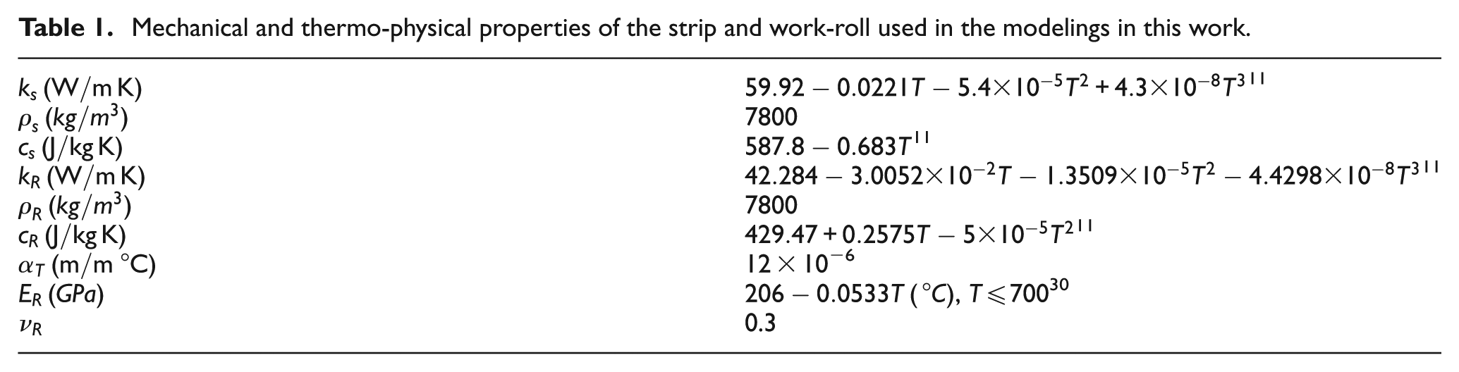
Mechanical and thermo-physical properties of the strip and work-roll used in the modelings in this work.
Solution procedures
In order to solve the above-mentioned thermo-mechanical problems in this work, first, the energy and thermal equations of the strip were solved. To do this, an initial guess for the velocity and temperature field was taken. The initial guess for the velocity field was taken according to Hill, 31 assuming homogeneous deformation. Next, the strain rate, strain and stress fields were computed in the deformation zone for the strip being rolled. Owing to the nonlinear nature of the energy and thermal equations, as well as the temperature dependence of thermo-physical properties of the employed steel, direct iteration solution procedure 32 was utilized to determine the accuracy of the obtained rolling variables, namely, the temperature and stress fields.
Rolling load and surface temperature were calculated in the next step, to be used as boundary conditions for solving the FE equations in the work-roll. Finally, strain and temperature fields were determined within the work-roll material applying the proper boundary conditions determined previously.
It should be emphasized that a mesh sensitivity analysis was also performed with the purpose of determining the optimum element number. To do this, variation of the relative difference in the value of primary variables, that are, nodal temperature and velocity components, with respect to the uniform mesh refinement stages was considered for both strip and the work-roll. The optimum mesh size was then chosen according to the “relative percentage error” criterion with the acceptance condition to be <3% for all the primary variables mentioned above. The actual mesh sizes used for the FE modelings in the present work are depicted in Figures 1 and 2.
Results and discussion
Thermo-mechanical modeling of the strip and the work-roll was performed for warm rolling operations on low-carbon steel strips with the rolling schedules shown in Table 2. By considering different rolling parameters such as initial strip temperature and rolling speed, the influence of these variables was studied on the thermo-mechanical behavior of work-roll, as well.
Details of the rolling schedule used in the finite element modelings in the present work a .
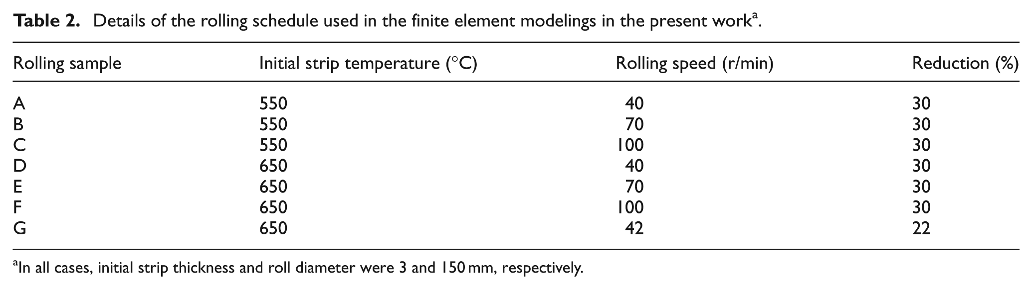
In all cases, initial strip thickness and roll diameter were 3 and 150 mm, respectively.
In the first stage, temperature distribution within the deformation zone of the rolled strips was obtained. For instance, temperature distribution within the deformation zone for sample “G” is depicted in Figure 3. Also, to demonstrate the temperature history on the surface and on center line of the rolled samples, temperature variation curves along the rolling direction were computed and compared with published data. Figure 4 displays the temperature variation on the surface and center line of the warm rolled sample “G,” along with the curves obtained for a similar rolling operation, reported previously in Serajzadeh. 7 Note that the modeling of the warm rolling process in Serajzadeh 7 has been performed based on an unsteady-state solution procedure. However, the comparison of the results found in the present work and those previously documented in Serajzadeh 7 may be used to assure that the results obtained here are of acceptable accuracy. Based on the results illustrated in Figure 4, a good agreement between the results of the present work and previously published data was found. Also, it is shown that a maximum temperature difference of up to 200 °C may exist within the deforming material during warm rolling process, indicating that a significant inhomogeneity in temperature distribution can be present in such rolling process.
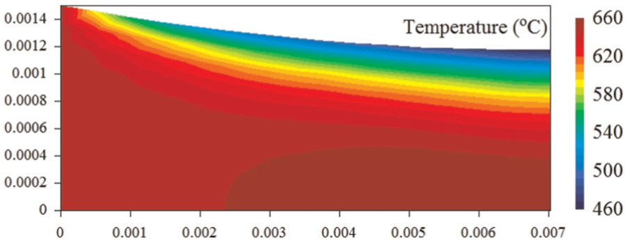
Contour of temperature distribution within the deformation zone, for sample “G.” The dimensions are in meter.
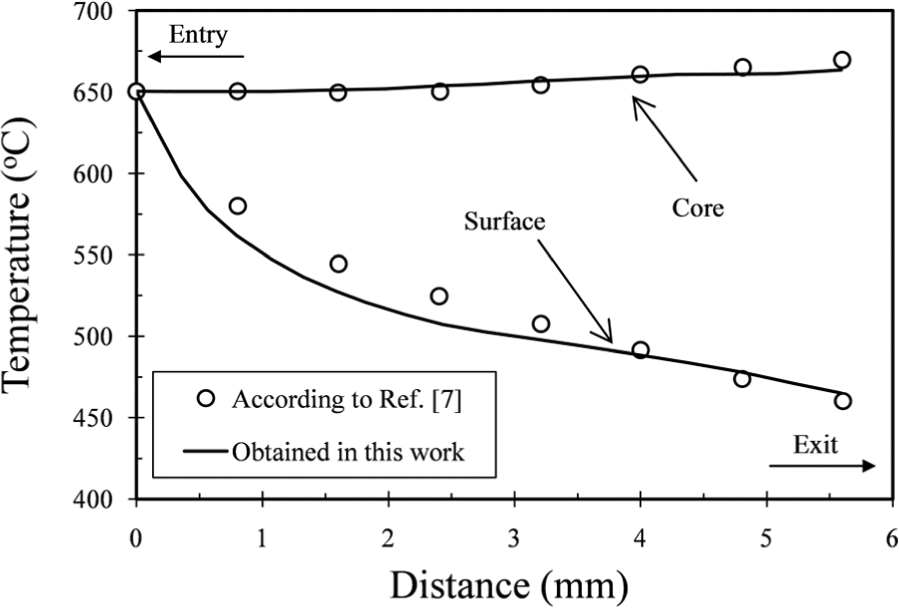
Variation of surface and core temperatures along the contact area, for sample “G.”
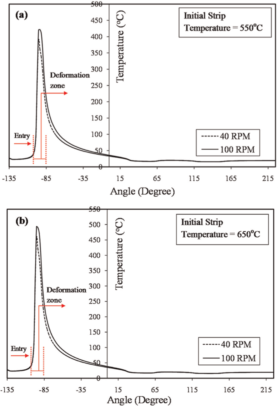
Temperature history curves of different rolling schedules in Table 2 were also obtained and were compared in Figure 5. It is found that the surface temperature undergoes a sudden drop as the strip enters the deformation zone. This kind of behavior is associated with the high value of convective heat transfer coefficient present at the interface of strip and the work-roll and causes the strip surface to experience a sudden decrease as it first makes contact with the work-roll. On the contrary, a temperature rise takes place within the strip core, as a consequence of the adiabatic heat generated in this region. It should be noted that the value of temperature change at different regions along the thickness of the rolled strip is highly affected by the rolling parameters utilized in the deformation process. For instance, a 30-r/min increase in the angular velocity of the work-roll was found to result in an 80 °C increase in the core temperature of the strip rolled with the same magnitudes of reduction and initial temperature. This can be explained through higher values of the developed strain rates affecting the adiabatic heat generation rate,
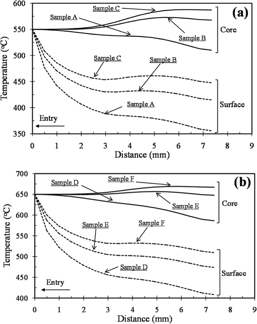
Temperature history on the surface and center line along deformation zone, for samples with initial temperatures of (a) 550 °C and (b) 650 °C.
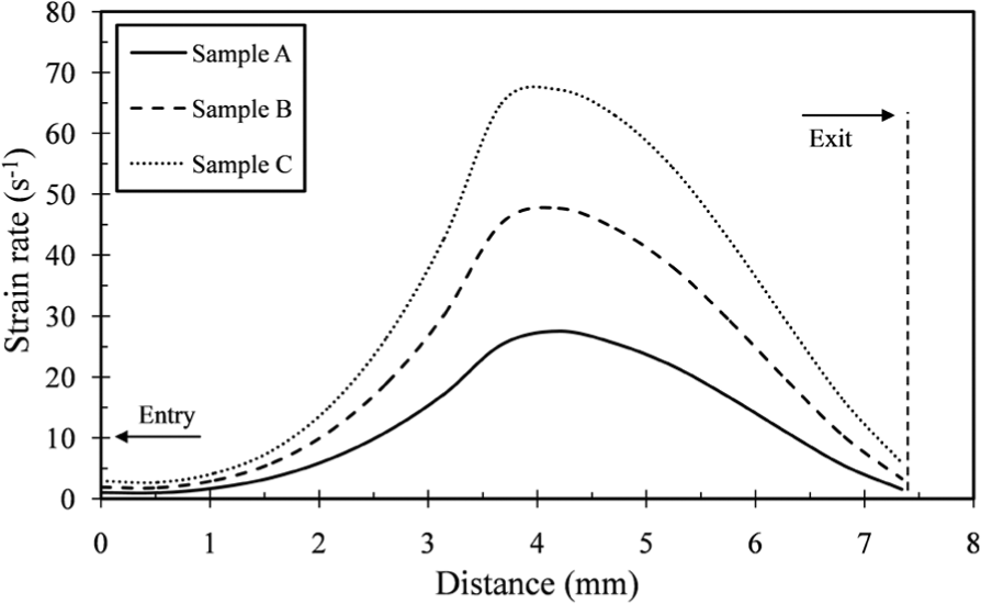
Variation of central-line effective plastic strain rate along deformation zone, for samples rolled with initial temperature of 550 °C.
Rolling speed has another noticeable influence in warm rolling operations. An increase in the value of this parameter leads to an increase in the strip temperature and consequently decreasing the flow stress of the material. The softer the material becomes, the lower rolling load, rolling torque and power are required. To give a clearer understanding of this fact, the variation of calculated rolling loads as a function of rolling speed is plotted in Figure 7. It is observed that for both values of the initial temperatures, that is, 550 °C and 650 °C, increasing the work-roll angular velocity has reduced the required load for rolling of the steel strips to a similar reduction.
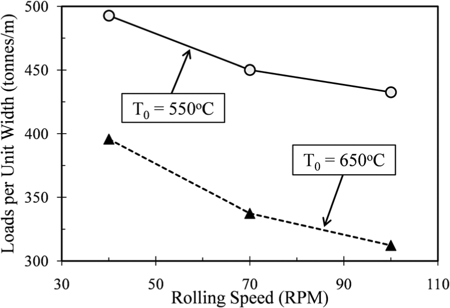
Rolling load versus rolling speed curves for different samples.
Another aspect worth mentioning in the observation of temperature history curves obtained for the samples within the deformation zone is that for both values of initial temperatures considered in this work, surface temperature of the samples rolled under lowest rolling speeds, that is, samples “A” and “D,” undergoes a more significant temperature drop. This may be explained through the fact that by decreasing the rolling speed, the strip-to-roll contact time increases, and as a result, the heat flux transferred to the work-roll material is increased, causing the surface temperature of samples rolled under lower rolling speeds to become lower.
Next, thermal and mechanical stresses developed in the work-roll were examined. First, to demonstrate the significance of mechanical loading on the deformation behavior of work-rolls in warm rolling schedules used in this work, mechanical stresses present within the roll material were taken into account. To do this, the second term on the right-hand side of equation (7) containing the term
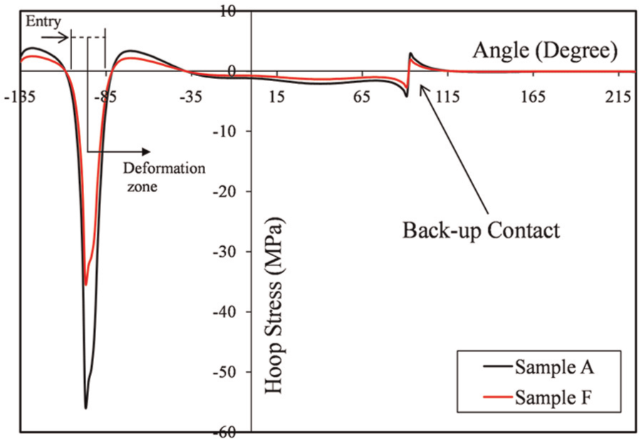
Variation of hoop stress (
To study the thermo-mechanical stresses within the work-roll, temperature distribution in the roll material was first determined. Surface temperature variation in the work-roll for different samples is observed in Figure 9. It is shown that reducing the rolling speed from 100 to 40 r/min has resulted in a decrease of about 30 °C in the maximum temperature value obtained on the roll surface. Additionally, after an approximately 100° angular travel, roll surface temperature takes a relatively steady temperature, such that a very slight temperature change occurs on the work-roll surface from this point forth. This may be attributed to the high value of ha used in the modelings in this work. Another point is the rather ineffective influence of backup roll on the thermal behavior of the work-roll. This can also be due to the facts that first, a very narrow contact area exists at the work-roll–backup roll contact zone, leading to a small amount of heat to be transferred from warmer regions of the work-roll to the backup roll. Second, as illustrated in the surface temperature history of the work-roll in Figure 9, a larger amount of surface temperature is lost on a 180° roll travel, from the point where the contact to the strip is ended up to the location where the roll surface reaches the first water spray. From this point forward, a very slight change in the surface temperature variation of the work-roll may take place; therefore, the effect of backup roll on this variable could be neglected. To provide a more detailed understanding of the above explanations, temperature distribution in the vicinity of backup roll contact for sample “F,” that is, the sample rolled under highest speed and with highest initial temperature, is presented in Figure 10. It is obvious that a negligible variation has taken place in thermal behavior of the work-roll as it passes through the backup roll contact area. Therefore, based on the explanations provided earlier, it can be stated that in high-temperature rolling operations, small attribution on thermo-mechanical stresses within work-rolls is due to the backup roll contact. However, note that the principal purpose in the use of backup rolls in practical rolling operations is to control the deflection of long work-rolls and to prevent the geometric inaccuracies possibly taken place in the product. 33 Therefore, the analyses including the effects of backup rolls might be of greater interest when three-dimensional modeling of the rolling process is to be performed.
Temperature variation along roll surface, for samples rolled under 40 and 100 r/min with initial temperatures of (a) 550 °C and (b) 650 °C. The strip–roll contact area is marked as the deformation zone.
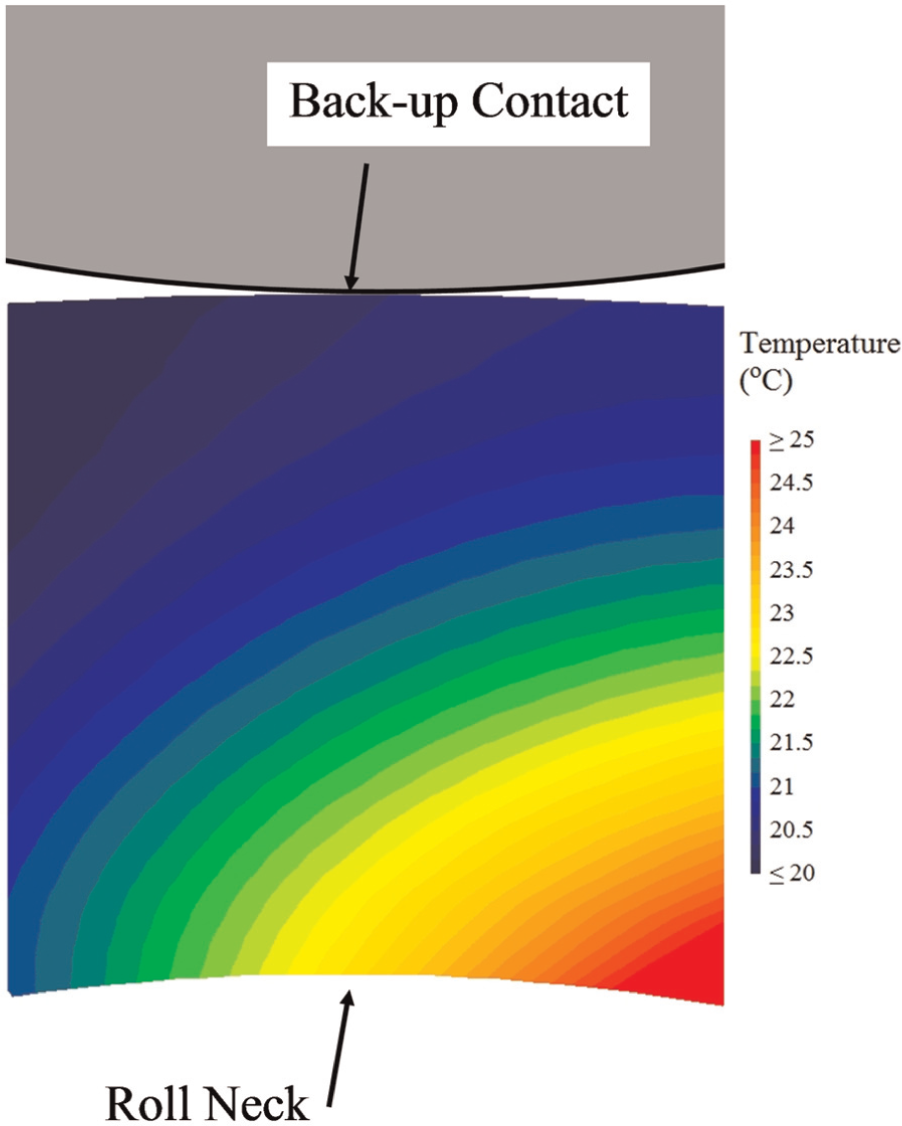
Contour of temperature distribution in the vicinity of the backup roll contact area. The temperature field is obtained for a sample rolled with 650 °C initial temperature and 100 r/min rolling speed.
In the next stage, using the temperature distribution obtained within the work-roll, thermo-mechanical stresses were also examined. In Figure 11, contours of the effective thermo-mechanical stress for samples “A” and “F” are depicted. Note that the effective stress in the work-roll material,
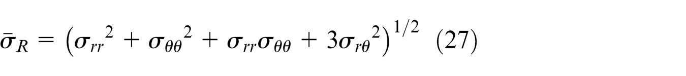
Comparing these contours with the distribution of the effective mechanical stress (Figure 11(c) and (d)), it is indicated that thermal loading has a more influential effect on the stresses developed in rolling mills during high-temperature rolling operations; however, the influence of mechanical loading on the warm rolling mills should also be taken into account in order for a sound rolling schedule to operate.
Distribution of effective thermo-mechanical stress within work-rolls for sample rolled under (a) 40 r/min and initial temperature of 550 °C, (b) 100 r/min and initial temperature of 650 °C. Distribution of effective mechanical stress (neglecting the thermal loading) within work-rolls for sample rolled under (c) 40 r/min and initial temperature of 550 °C and (d) 100 r/min and initial temperature of 650 °C.
Considering the data obtained in this work, it was found that by increasing the rolling speed, the rolling loads are reduced and as a consequence, the mechanical stress developed in the work-roll also decreases. On the contrary, increasing rolling speed may result in higher surface temperatures on the rolled strip, increasing the thermal stresses within the work-roll. Therefore, thermal stresses would be higher for the samples rolled under higher rolling speeds, particularly at the surface region of the work-rolls. The similar behavior was observed for different initial stock temperatures, as well.
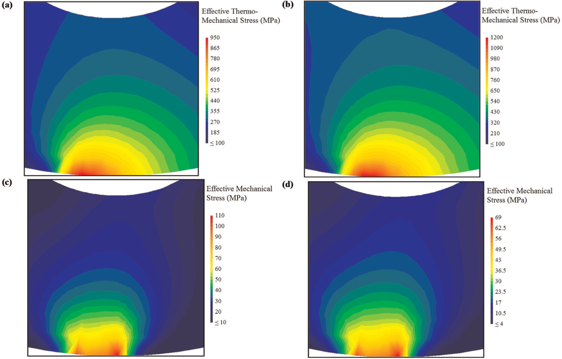
An examination was also performed with the purpose of studying the influence of water spray cooling layouts on the thermal behavior of the work-rolls. For this case, an industrial scale rolling schedule was taken into account, with details shown in Figure 12(a). Two different cooling layouts were examined, with the water spray locations shown in the schematic view. The developed surface temperature curves were compared for two cooling layouts. Figure 12(b) displays the variation of temperature regarding two different cooling layouts within the work-roll for rolling conditions detailed in Figure 12(a). It is observed that a slight change occurs in the thermal history of warm rolling mills as a result of varying the coolant positions; however, the most significant aspect in the cooling of the work-roll, as shown in this work, is the section of the roll located between the roll gap exit and the first water spray, where a remarkable change in the surface temperature of the work-roll takes place. Note that from this point forward, the temperature variation within the roll is so small that a negligible change of the thermal stresses is likely to occur.
(a) Schematic view of the two different cooling layouts used for modeling of a practical rolling schedule, with details shown on the right and (b) work-roll surface temperature history during one angular travel with the magnified view of the water spray region.
Conclusion
A study was performed on the effect of different rolling parameters, that is, strip initial temperature and rolling speed, on the deformation behavior of strips and work-rolls in warm rolling of steel strips, with emphasis on the thermo-mechanical stresses developed within the warm rolling mills. The significance of the present work can be stated to be the investigation of both mechanical and thermal loadings during the warm rolling operations, as these both are remarkable phenomena influencing the deformation behavior of the rolling mills in this particular metal forming process. It was shown that the rolling speed acts as a more influential parameter on the thermo-mechanical behavior of the warm rolling work-rolls. The results indicated that by increasing the value of this parameter from 40 to 100 r/min, for a constant initial strip temperature, the developed thermal stress within the roll material increases, while mechanical stresses are reduced. A total of 10% and 21% decrease in the roll force magnitude were documented when the rolling speed was increased from 40 to 100 r/min, for the initial strip temperatures of 550 °C and 650 °C, respectively. It was also found that the effect of backup roll on thermo-mechanical behavior of the work-rolls is negligible. A quantitative examination on the values of both mechanical and thermo-mechanical stresses developed within the work-roll revealed that the effect of both mechanical and thermal loads should be taken into consideration, in case a more accurate life time prediction and roll material selection are to be conducted in the warm steel rolling operations.
Footnotes
Acknowledgements
The author wishes to express his gratitude to Prof. Siamak Serajzadeh in the Department of Materials Science and Engineering, Sharif University of Technology, for valuable discussions on the subject.
Declaration of conflicting interests
The author declares that there is no conflict of interest.
Funding
This work received no specific grant from any funding agency in the public, commercial or not-for-profit sectors.