
Abstract
Developing improved coated cutting tools to achieve a better cutting performance is one of the key factors in enhancing machining productivity. The present article contributes to the development of electrostatic solid lubricant coating technology to produce high-performance coated tools for machining process improvement. Machining tests and finite element analysis were performed to evaluate the proposed novel coating technique. The results obtained from the experiments and simulations demonstrate the effectiveness of the presented technology in reducing the generated heat during machining as well as enhancing wear characteristics of the tool. The results also prove that the developed solid lubricant coating technique will play an important role in sustainable machining.
Keywords
Introduction
Surface coating is an effective method to improve the durability of the cutting tools used in aggressive machining (such as dry machining). Surface coating also decreases heat generation and consequently reduces tool wear. The first generation of physical vapor deposition (PVD) coatings, which were applied in cutting processes, featured titanium nitride (TiN) as a hard coating. 1 However, hard coatings retain a high coefficient of friction and require lubricants to dissipate the generated heat during machining from the cutting zone. These features make the hard coatings an inappropriate choice for some practical applications, particularly when machining advanced difficult-to-cut engineering materials.
Utilizing solid lubricants in machining processes is one of the possible solutions to solve the issues arising in machining hard-to-cut materials. It has been shown that the cutting force can be controlled using solid lubricant–coated inserts. 2 Moreover, solid lubricant tools do not experience as serious wear rate as that of conventional tools due to lower cutting forces and friction coefficient at the tool–chip interface. The analysis of using solid lubricants during end milling demonstrates their outstanding characteristics by showing that the specific energy consumed during cutting process under solid lubricant machining is lower in comparison with wet machining. 3 Another research work 4 investigated the possibility of using composite solid lubricant coatings on the shaft surfaces of foil air bearings in an oil-free aircraft engine bearing to prevent wear and reduce friction. They simulated the conditions to check the performance of solid lubricant coatings on bearing surfaces in terms of wear and surface finish.
Investigations of the performance of cutting tools5,6 have shown that coating the tools with solid lubricants is an effective way to improve their durability and tribological characteristics for a safe and smooth operation. Recently, the application of a novel concept, 7 namely electrostatic spray coating (ESC), in the deposition of micro/nano solid lubricant particles on the tool substrates has been successfully explored. In another similar study, 8 the application and performance of composite coatings on the cutting tools were analyzed and compared to those of the conventional coating techniques such as PVD and chemical vapor deposition (CVD).
The review of literature reveals that the use of solid lubricants in machining improves the process performance; however, very few efforts have been made on the use of solid lubricants, such as molybdenum disulfide (MoS2) and graphite, as coating materials on the cutting tools. Furthermore, very limited research exists to provide an understanding of the process performance in terms of cutting forces, tool wear, cutting temperature, and tool–workpiece interaction during machining with solid lubricant–coated tools. As a result, investigating new coating materials and methods, which are less expensive than CVD and PVD techniques, will be the focus of future research to achieve a sustainable machining system. In this context, the primary objective of the present article is to develop a novel electrostatic micro-solid lubricant (EMSL) coating system for the cutting tools to facilitate the production of environmentally friendly MoS2 solid lubricant–coated tools. The secondary objective of this article is to compare the effectiveness of EMSL-coated tools with uncoated tools during turning of high-strength aluminum alloys. To analyze the effect of solid lubricant in terms of temperature and cutting forces, a finite element (FE) model was developed and used to simulate the machining process using ABAQUS/Explicit commercial FE software. The results obtained from the experiments and FE simulations confirm the effectiveness of solid lubricant–coated tools as a viable alternative for traditionally coated tools to enhance the machining processes.
Development of solid lubricant–coated tools
A schematic illustration of experimental setup for EMSL coating deposition process, which was specifically developed for this investigation, is shown in Figure 1. The electrostatic spraying unit comprises a high-voltage (HV) generator with air/powder pressure controls, electrostatic spray nozzle assembly, powder container, air compressor, and tool holder (X–Y stage). The electrostatic nozzle assembly (Figure 1) is the most important component of the electrostatic spray system as its structural design directly affects the spraying transfer efficiency.
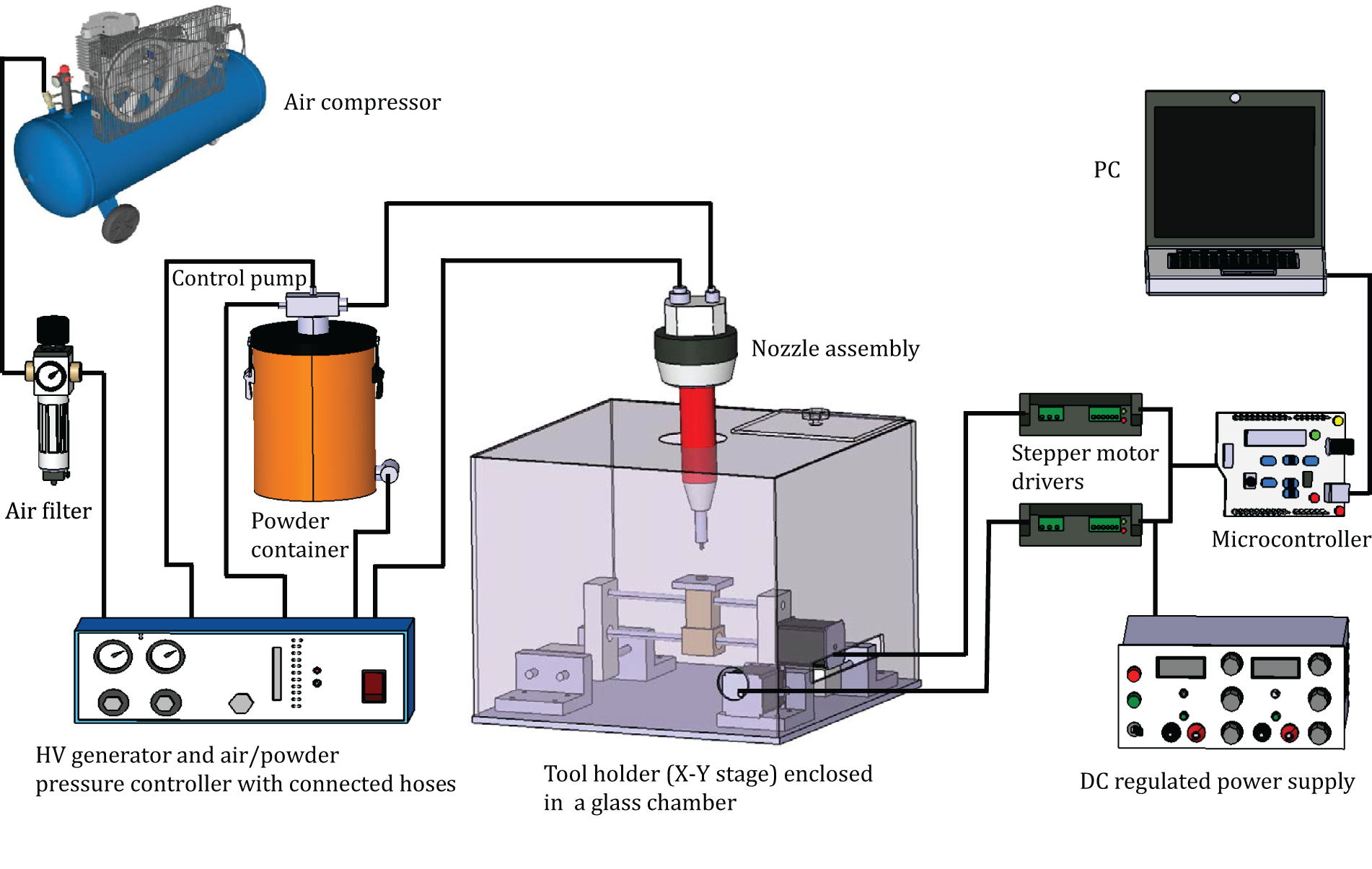
Schematic diagram of EMSL coating deposition experimental setup.
The main function of the nozzle is to shape and direct the flow of powder particles with electrostatic charge. It contains an HV cascade that is cast into a cylindrical barrel made of the insulating material, nylon, and connected to a transformer. The delivery tube, placed inside the nozzle, carries the electrical components of the HV cascade. The inside bore of the delivery tube can serve as a holder for the HV stranded electrode. The system employs the corona charging principle (low-amperage field) to convey the electrostatic charge to the powder particles. Electrostatic charging occurs while the particles are passing through the comb-like corona charging device located at the tip of the nozzle. A powder container that is connected to the air compressor is used to hold the solid lubricant powder. Charging voltage is selected in the range of 0–100 kV. In the electrostatic coating process, the solid lubricant powder (MoS2) in the form of submicron-sized particles, mixed with pure modified submicron-sized phenolic novalac resin powder, is initially loaded into the powder container. It is then fluidized by blowing air and fed into the electrostatic spray nozzle with the aid of the compressor. The air compressor fluidizes the powder particles by passing air through the container and then transports (with a pressure of 2 bar) the powder to the nozzle. A voltage of 80 kV is applied to the nozzle to charge the powder particles electrically and enable them to stick to the cutting tool surface. The tool is positioned on the X–Y stage with a distance of about 140 mm from the nozzle tip. The powder flow is regulated by controlling the air supplied to the powder container.
The tool holder (X–Y stage) holds the substrate in the coating chamber during coating deposition. The working principle and schematic view of the X–Y stage are shown in Figure 2. The X–Y stage has a maximum travel limit of 250 mm in both X and Y directions and was built based on modularized design using commercially available stepper motors and Acme lead screws according to the industrial manufacturing standards. The stage is made of lightweight aluminum alloy to provide high stiffness and long-term stability. Linear bushing (LM12UU) and ball bearings (SKF 16100) are also utilized to reduce the friction and achieve smoother motion. The precision high torque stepper motors (two phase, 2 N m, standard NEMA 23; Leadshine) plus lead screws (Acme, 10TPI, stainless steel 304) provide the accurate positioning of the workpiece. The stepper motors interfaced with microcontrollers offer the needed positioning performance. The motion of system is controlled using personal computer programmed with Arduino software.
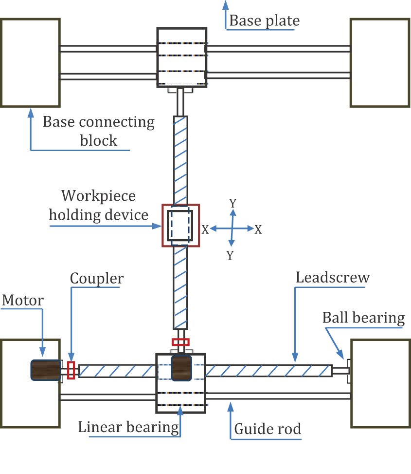
Working principle and schematic of the X–Y stage.
Experimentation
Turning experiments were performed on a computer numerical control (CNC) lathe. The workpiece material used in the turning process is Al7075-T6, which is widely used in automotive and aerospace industries, due to its high strength-to-density ratio. Cutting tests were carried out on cylindrical workpieces with initial length and diameter of 400 and 70 mm, respectively. The tests were performed using uncoated and solid lubricant–coated inserts in the absence of any external coolant. The details of the process parameters used in this investigation are presented in Table 1.
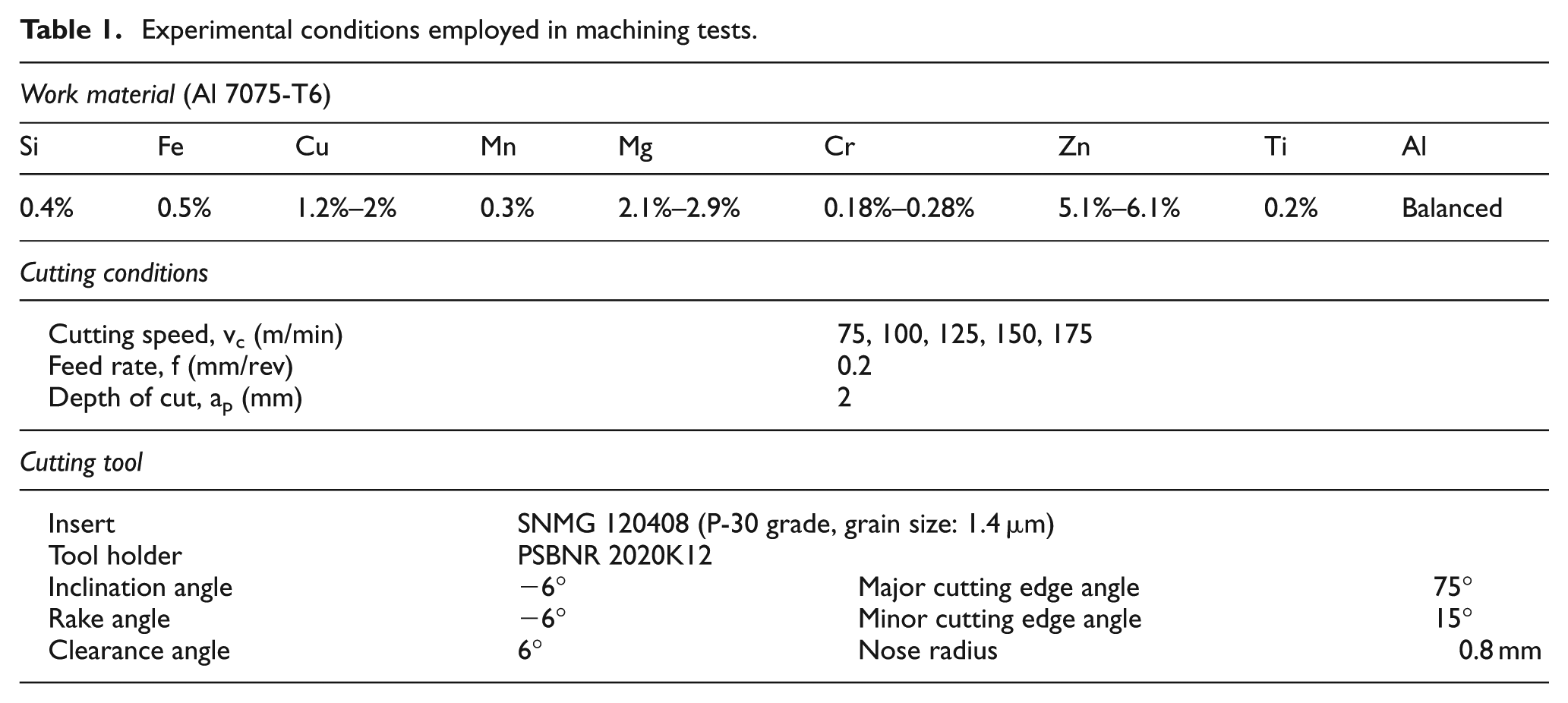
Experimental conditions employed in machining tests.
A three-component strain gauge dynamometer was employed to acquire the cutting forces generated during the tests. Only the steady-state phase of cutting tests was analyzed. Cutting temperature at tool–workpiece interface was measured by means of a thermal infrared camera (FLIR E60). The camera has a resolution of 320 × 240 pixels with a thermal sensitivity of 0.05 °C at 30 °C.
FE simulation
The performance of a cutting tool is mainly evaluated based on its capability to maintain its geometry at elevated temperature (hot hardness). Form stability is one of the important characteristics of cutting tools, which is greatly influenced by the heat generated during machining. The generated heat is normally considered to be an undesirable phenomenon that not only accelerates the tool wear rate but also influences the mechanical properties of workpiece material. The direct measurements of temperature at the tool–chip and tool–workpiece interfaces are very difficult due to the dynamic nature of cutting as well as the small contact areas. In such cases, the FE simulation provides a quick and accurate prediction of temperature under different machining conditions in a virtual environment.
In this study, the effectiveness of the use of solid lubricant–coated tools in terms of machining temperature was analyzed using ABAQUS/Explicit with Lagrangian modeling approach. The model was meshed using quad thermal-displacement plane strain elements. Model results were confirmed to be independent of mesh size through comparison with the results obtained from a model with smaller mesh size. Cutting force was used as the benchmark for this comparison. Figure 3 shows the meshed parts for the FE analysis in the software.
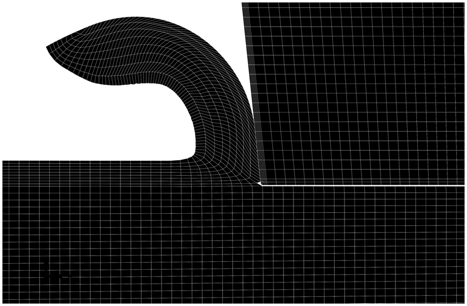
Meshed parts of finite element model.
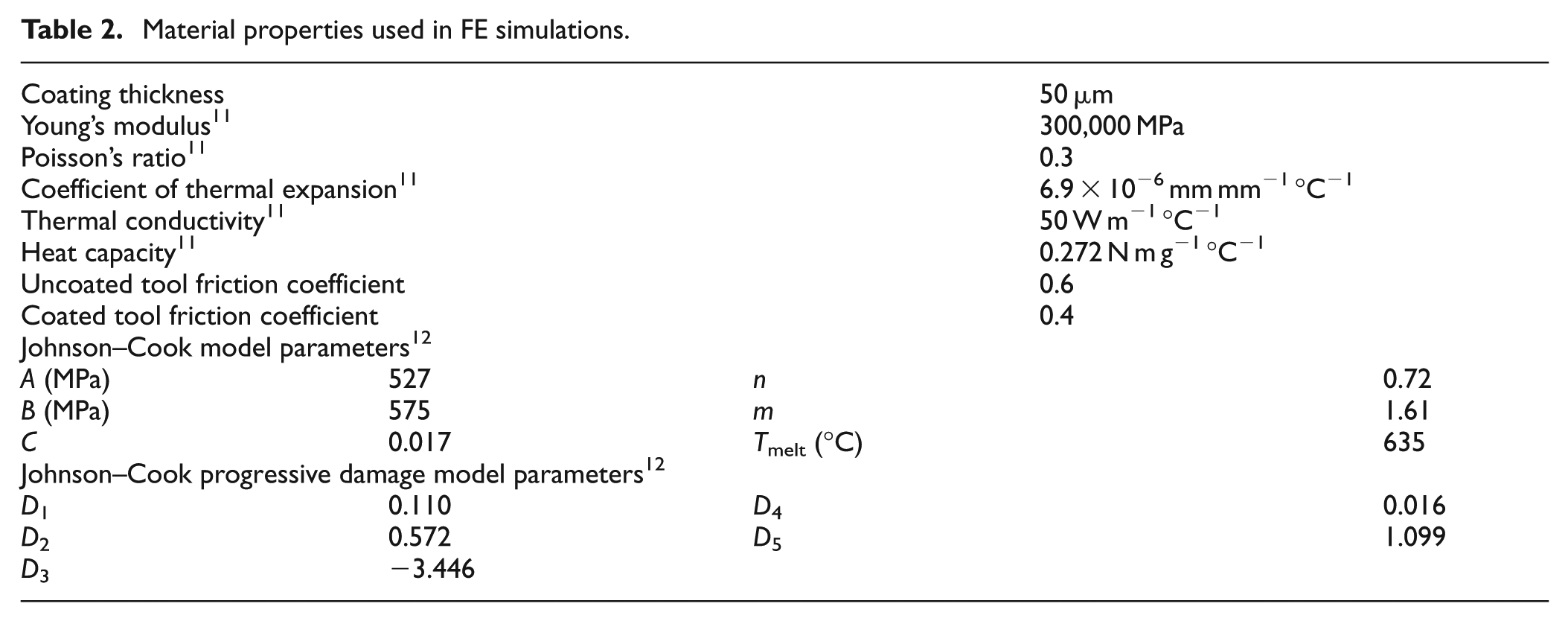
The FE simulation results were compared with experimental results under similar cutting conditions. The Johnson–Cook 9 material model was used to represent the thermo-viscoplastic behavior of the workpiece material. Chip separation is simulated through element deletion in a sacrificial layer of elements. Element deletion is modeled using Johnson–Cook’s 10 model for progressive damage and fracture. Mechanical and thermal properties used in FE simulations are presented in Table 2. Constant velocity boundary condition was used on the cutting tool while the movement of the bottom surface of the workpiece was restricted in all directions. Coulomb friction was assumed along the tool–chip interface. This assumption is based on the outcome of the research available in the literature regarding FE modeling of machining. 13 The friction coefficients, provided in Table 2, were found using pin-on-disk tests. Heat transfer at the contact surfaces is modeled using gap conductance model. Thermal conductance for zero gap clearance was considered to be 106 W m−1°C−1, while conductance for 0.01 μm gap clearance was 103 W m−1°C−1. These values match the values used in similar FE models for simulation of cutting process. 14
Material properties used in FE simulations.
Results and discussion
To evaluate the performance of solid lubricant–coated tools at different cutting speeds and to understand their influence on contact temperature and cutting forces, a comprehensive investigation was conducted. The generated cutting forces and the temperatures at the tool–workpiece contact zone were selected as performance criteria.
Effect of solid lubricant coating on cutting force
Cutting force is one of the most important parameters in predicting the effectiveness of the tool performance. Any improvement in tool–workpiece interaction, by minimizing the friction, will affect the cutting force and positively influence the tool performance. Previous investigations revealed that the presence of MoS2, either in the form of coatings or direct supply to the machining zone, leads to reduction in cutting force compared to that of conventionally coated tools.
The variation of cutting force generated in experiments and FE simulations versus cutting speed using uncoated and solid lubricant–coated tool is presented in Figure 4. The improvement in the machining performance of EMSL-coated tool is evident, as shown in Figure 4; cutting forces were reduced by an average of 15% under all tested conditions. As can be seen from Figure 4, the experimental and simulated cutting forces are in good agreement. Moreover, it can be clearly seen that the magnitude of cutting force when machining with coated tool is smaller than that of uncoated tool. This is mainly due to the effective lubricating action of the solid lubricants, which reduces the frictional forces in the tool–chip and tool–workpiece interfaces. As a result, reduced interface temperature along with lower tool wear rate and prolonged tool life is expected. The lower values of cutting force produced by the MoS2-assisted machining can also be attributed to its strong adhesion and the inherent lubricating properties even at high temperatures.
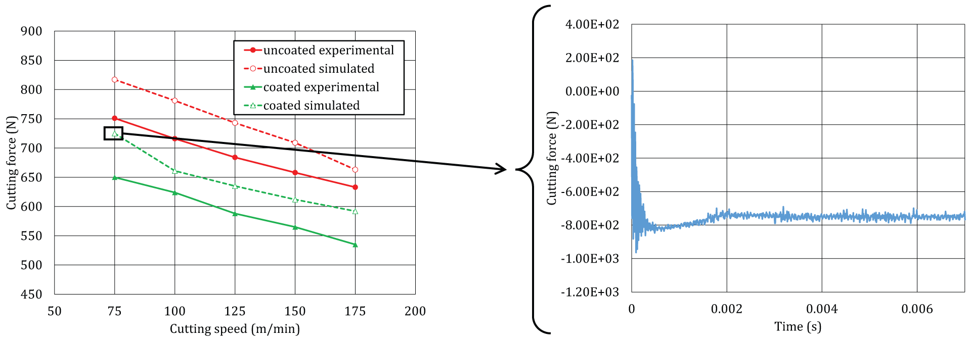
Experimental and simulated results of cutting forces at different cutting speeds during machining of Al7075-T6.
Effect of solid lubricant coating on temperature
The measured and predicted temperatures generated around the cutting edge for coated and uncoated tools are shown in Figure 5(a). Figure 5(b) and (c) shows FE simulations of temperature contours around the cutting region at a selected cutting speed during machining.
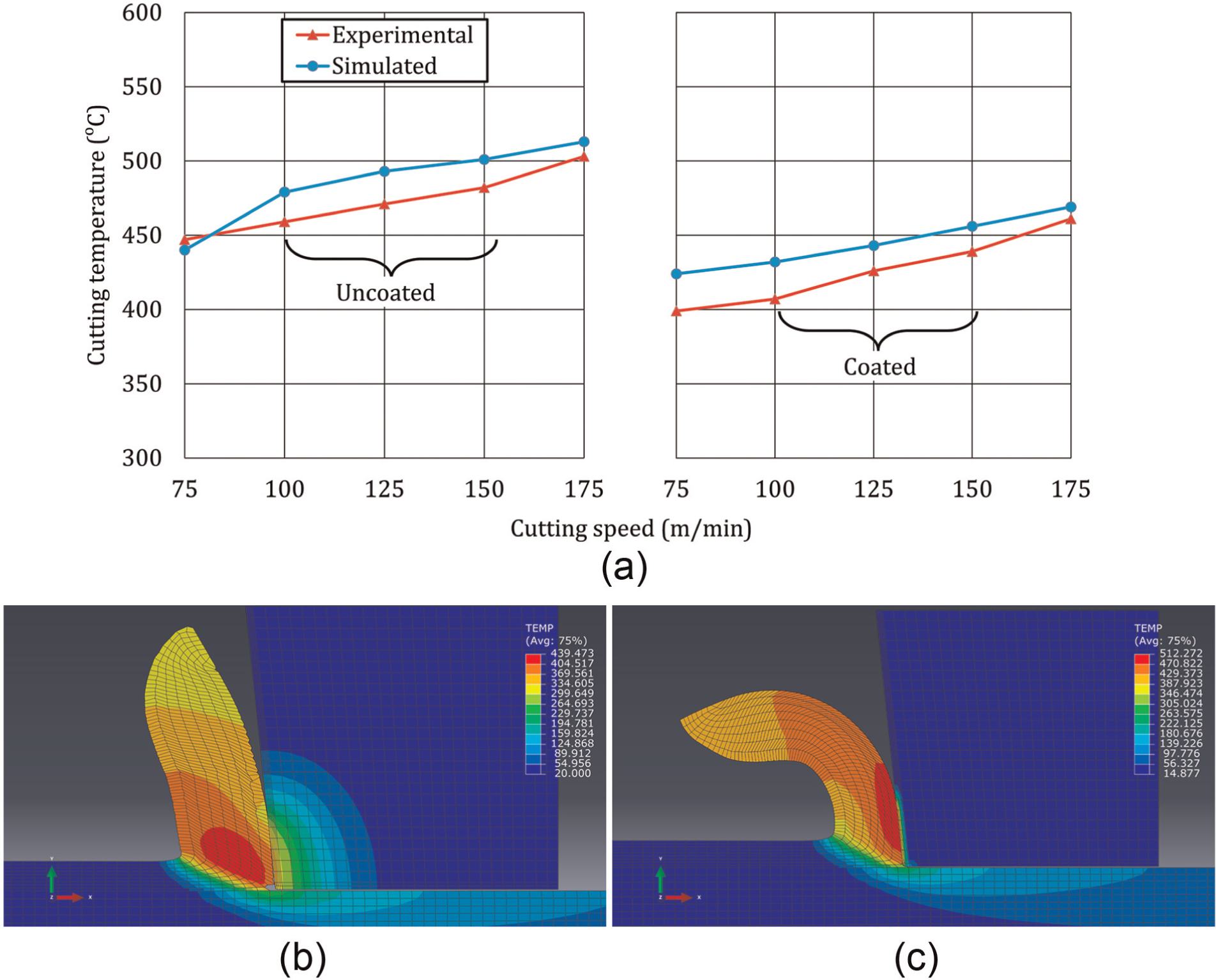
(a) Experimental and simulated results of cutting temperatures at different cutting speeds. (b–c) Finite element model (FEM) simulations of cutting temperatures (°C) at selected cutting speed (75 m/min) during machining of Al7075-T6 with (b) non-coated and (c) coated tools
As can be seen from Figure 5, in comparison with the uncoated tool, the cutting temperature developed during machining with coated tools is rather low. It is evident from the temperature contours shown in Figure 5(b) and (c) that due to the low thermal conductivity of solid lubricant coating, the temperature in the cutting tool beneath the coating is about 60% lower in comparison with the uncoated tool. This obviously demonstrates the advantage of the presented coating technology in terms of extending the tool life. In addition, the presence of MoS2 as a transfer film at the tool–chip and tool–workpiece interface reduces the friction and thus shear stress in the secondary and tertiary shear zones due to lower shear force within the contact area. This consequently lowers the heat generated, which is an essential step toward improving the performance of the cutting process.
Figure 5(b) and (c) also illustrates the difference in the shape of chips generated when cutting with coated and non-coated inserts. As can be seen, cutting with non-coated tools results in chips with larger curl radius, while coated tools lead to the formation of chips with tight and small curl radius. This observation is in agreement with the experimental observations, as shown in Figure 6. In this figure, the chips formed when machining with coated and non-coated tools are compared. The difference in the chip shape is due to the low thermal conductivity of the solid lubricant coating, which results in a large thermal gradient across chip thickness and tighter chip curls. 15
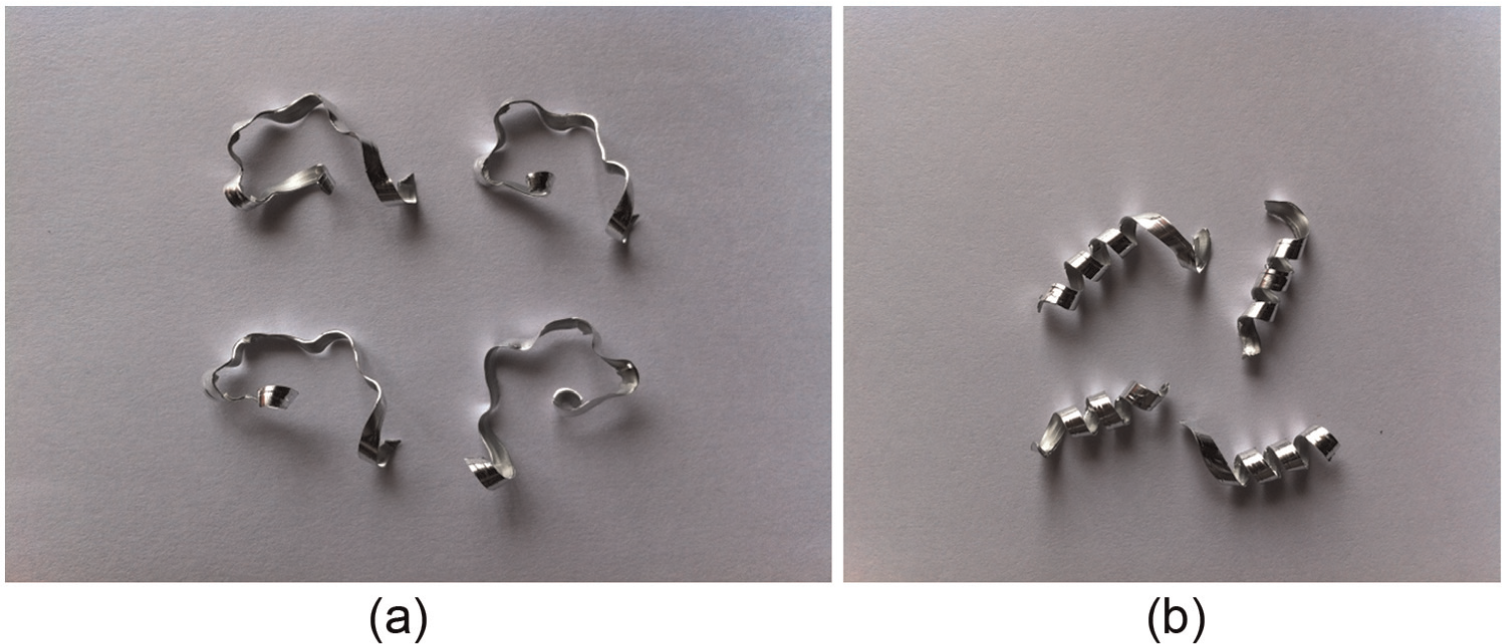
Chips formed during cutting (cutting speed: 75 m/min): (a) using non-coated insert and (b) using coated insert.
Conclusion
In this article, the EMSL coating technology is proposed as a useful alternative to the conventional coating techniques for cutting tools. An attempt was made to study the contributions that MoS2 coating makes in enhancing the performance of carbide inserts. Cutting force and cutting temperature were used as performance measures of the developed solid lubricant–coated tools. Results obtained from turning Al7075-T6 using newly developed coated inserts demonstrated comparatively lower cutting forces and temperature during the process. Hence, the developed coated tools exhibited improved wear characteristics and showed an overall good performance during machining. The developed coating technology holds a great potential and offers interesting opportunities in machining wide range of materials from soft to hard along with substantial economic advantages. Further investigation related to studying tribological characteristics is required to optimize the performance of the developed MoS2 solid lubricant–coated tools.
Footnotes
Declaration of conflicting interests
The authors declare that there is no conflict of interest.
Funding
This research is funded by the Natural Sciences and Engineering Research Council of Canada (NSERC).