
Abstract
In groove design, a proper shape should be chosen during the preparation for the welding of thick plates of steel structures to minimize the potential for any welding deformations. While the effect of welding on both sides of the plate in terms of the deformation potential is a foremost consideration during the groove-design process, the effect of gouging is not included even though it involves the usage of a high-heat arc input that may significantly influence the welding-deformation potential. In this study, the effect of the air-carbon-arc gouging process on the deformation of steel plates was investigated using a numerical finite element method analysis. For this purpose, the heat input from the gouging torch was first modeled using an analytical solution that is based on the Rosenthal equation. The model was then used as a heat input for the thermo-mechanical steel-plate-gouging model that is proposed in this study to obtain deformation estimations during the gouging process. A series of numerical analyses were carried out to predict the deformations according to changes in the plate thickness. The results of the analyses were found to be in sound agreement with those of the experiments that were performed to verify the simulations. The comparison revealed that the models that are proposed in this study are feasible ways of estimating the deformation caused by the gouging on steel plates.
Keywords
Introduction
Thick steel plates have become widely used in ocean structures that must endure under severe conditions.1,2 The fabrications of these structures are mostly comprised of the welding process to produce X-shape-grooved thick plates that uses previous preparations that involve a square cutting in the thickness direction, followed by groove cuttings on the upper and lower surfaces. According to the welding procedure, the upper part of the X groove is first welded layer by layer, followed by an arc gouging after the plate is turned over to make the bottom side of the weldment of the upper groove suitable for the subsequent welding of the lower part; finally, the lower groove is welded from the gouged surface. Meanwhile, for the preparation of the X-shaped groove, the ratio of the size of the upper part to that of the lower part can be determined by taking into account the angular distortions of the plates in the welding process that need to be minimized.3,4 The appropriate ratio should, however, be further adjusted for the control of the distortion when a gouging process is additionally applied on the root of the weldment of the upper groove. 3
There have been many studies on the angular distortions of thick steel plates during the welding process with respect to the mechanism of the distortions and a reduction method that involves the adjustment of the groove sizes.5–7 Ye et al. 8 used a numerical simulation and experiment to reveal that the groove type in the V, K, and X groove joints had a significant influence on residual stress, angular distortion, and the width of the sensitization region in a SUS 304 butt-welded joint; however, they did not report the influence of the gouging process. Ha et al. 9 evaluated heat affection according to the gouging height using a numerical finite element method (FEM) analysis that calculated the temperature distribution in the base metal during the removal of temporary attachments. In the thermal model of the study, however, only the arc distribution that was located at a fixed position on the workpiece was considered a heat input, and the model is too simplified to describe the gouging process.
Meanwhile, the effect of gouging has been rarely studied in terms of the distortion of the plate during the welding process; accordingly, to find the proper ratio of the size of the upper side to that of the lower side in the X-shaped groove to minimize the potential of a thick-plate welding distortion, the effect of the gouging process on a distortion needs to be examined. In this case, a numerical FEM model is preferred due to its efficiency, which is in contrast to experimental methods that are expensive and difficult to obtain available results from.10,11 For this purpose, a heat-source model needs to be developed in advance for the air-carbon-arc gouging process that comprises arc heating and melting, convection by a high-speed air stream, and the removal of the melted part of the root.
In this study, an analytic heat-source model based on an analytical solution of the Rosenthal equation was suggested to heat the front line of a gouged surface for the gouging process. 12 Thermal and mechanical models were then developed for the thermal distribution and distortion of the steel plate during the gouging process with respect to the suggested heat-source model. The thermal and mechanical analyses of the models were carried out numerically using the FEM. To overcome the limitations of the calculation time and memory capacity of our computer, two-dimensional analyses were performed on the mid-section that is transverse to the direction of the gouging with an assumption that the travel speed of the gouging torch is much faster than the heat-conduction rate in the direction of the gouging. 13
The effect of the gouging process on angular distortion was examined using the developed model with a series of analyses whereby the thickness of the plate was varied. The analyses were also carried out to consider the effect of a change of the material on the deformation whereby the mild-steel plate was replaced by the AH32-steel plate. In addition, to validate the gouging-process models, the results of the thermo-mechanical analyses were compared with those of the experiments with respect to the size of the heat-affected zone (HAZ) and the angular-distortion amount.
Thermo-mechanical analysis
A schematic diagram of the air-carbon-arc gouging process is shown in Figure 1. The process is commenced by striking the electrode tip onto the workpiece surface to initiate the arc; consequently, an electric arc is generated between the tip of a carbon electrode and the workpiece. The metal directly under the electrode tip becomes molten, and high-velocity air-jet streams travel down the electrode to immediately blow the molten metal away, leaving a clean groove. The electrode diameter is selected according to the required depth and width of the gouge. The groove width is determined by the electrode diameter, while the depth is dictated by the angle of the electrode to the workpiece and the travel rate. 14
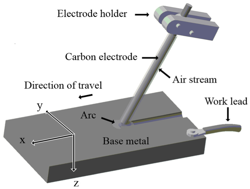
A schematic diagram of the air-carbon-arc gouging process and the Cartesian coordinates.
In the numerical simulation, steel-plate-based gouging process should be modeled three dimensionally. The calculation time and memory capacity for the numerical model, however, would be too excessive for the three-dimensional analysis; therefore, considering that the speed of the gouging process is much faster than the heat conduction rate, and a long workpiece would allow for a uniform distribution of temperature along the gouging path, a lengthwise thermo-mechanical model that is only in the mid-section of the plate was developed in this study to simulate the temperature distribution and distortion of a mild-steel plate. The simulation included the uncoupled thermo-mechanical finite element analysis method. 15
Heat source modeling
The model of the gouged shape and the relative position of the solution domain are presented in Figure 2. The gouged shape has a half cylindrical model with a width of 2W and a depth of d; meanwhile, the fore shape of the gouged surface has a linear slope with a length of Lx at the upper surface and a length of 0 at the lower surface.
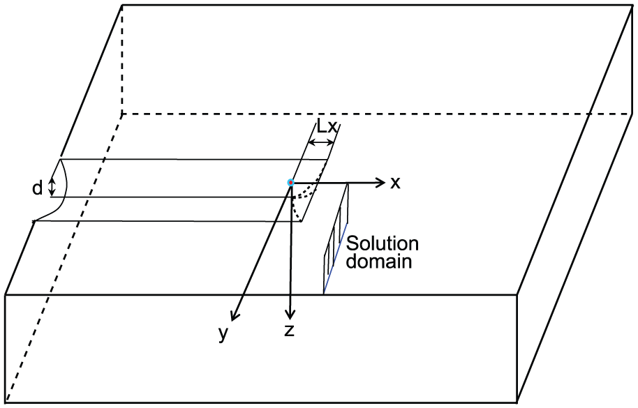
Model of gouged shape and relative position of solution domain in Cartesian coordinate system.
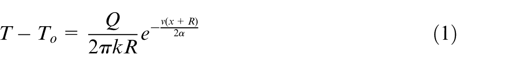
The gouged part would be heated up to the melting temperature and then removed; therefore, the new edge of the gouged part was heated up to the melting temperature and then cooled down by convection over the elapsed time. To model the previous heating of the solution-section domain, the analytic solution of the Rosenthal equation for a three-dimensional analysis of a heated workpiece with a moving heat source 12 was used to predict the temperature-distribution changes of the domain. According to the three-dimensional Rosenthal equation, when the coordinate system has its origin located at the center of the heat source, as shown in Figure 2, the analytic solution for temperature T at locations x, y, and z in the coordinate system, with the heat source Q moving at a speed of v, can be simplified in the following way
where
The heat input for the gouging can therefore be derived using the following equation

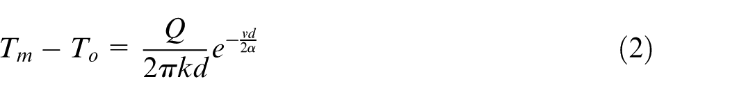
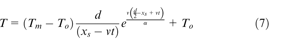
When equation (3) is substituted for equation (1), the temperature is presented in terms of Tm as follows
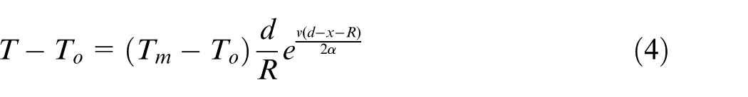
Meanwhile, at x = Lx, y = 0, and z = 0, R is equal to the length of the front melting zone on the upper surface that is lengthwise of Lx, and the temperature becomes Tm, as follows
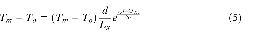
The following relation is therefore derived
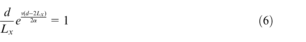
In this relation, Lx can be obtained when the other input parameters are given. When
On the upper surface, as shown in Figure 3, it was assumed that the solution domain starts to be affected by the heat source in terms of temperature when the relative distance of xs between the heat source and the solution domain is equal to the equivalent radius
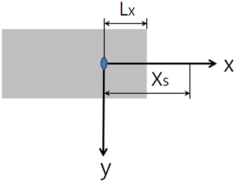
The relative distance of xs between the center of the heat source and the solution domain.
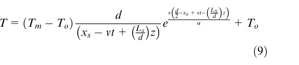
A distance of x between the front line of the groove is therefore generated with a speed of v and the solution domain becomes
Below the upper surface, and through the depth, the length of the front melting zone reduces from Lx to 0 at the lower surface; therefore, the relative distance x between the front line of the groove at a position of z and the solution domain can be represented in the following way when
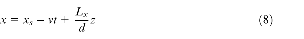
Accordingly, the temperature of the solution domain can be presented in the following way
The temperatures at the positions located on the gouging surface were estimated from the analytic solution of the Rosenthal equation that was used as a temperature input for the solution domain during heating. The temperature changes with the elapsed time could be used as boundary conditions for the gouging line of the solution domain. When the time of t elapsed beyond
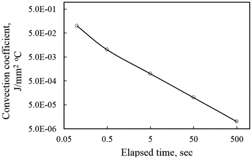
Convection coefficient enforced on the gouged surface during cooling.
In this study, the modeling parameters for the heat input are
Thermal analysis
A thermal analysis of a steel plate during the arc-gouging process was conducted using the numerical FEM. During the gouging, the governing finite element equation for the transient heat-transfer analysis can be expressed in the following matrix form

where
The division of the typical solution domain by the finite element meshes is shown in Figure 5, where the gouging of the shape is presented, for a 240-mm-wide and 30-mm-thick plate. A total of 30,000 quadratic elements with four nodes at each element were used for the solution domain. Finer elements were used adjacent to the groove and in its vicinity, while coarser elements were used for the area far from the surface. Considering the symmetrical condition when the torch is located at the center of the plate widthwise and is moving over the surface, only half of the plate could be analyzed. A temperature-boundary condition that was derived from the heat source model was enforced onto the gouged surface during heating. We assumed that all of the surfaces of the solution domain lost heat to the surrounding air through convection. The convection heat-transfer condition was also taken into account on all of the surfaces during cooling, with the exception of the symmetric surface where and adiabatic condition was enforced.
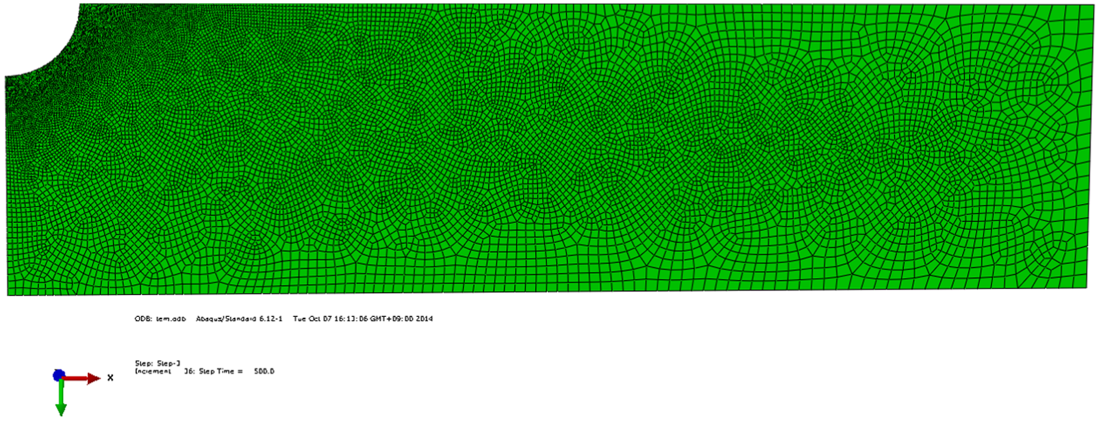
Finite element meshes on solution domain of 30-mm-thick plate.
The thermal properties of the steel plates that were used in this study are related to temperature, as shown in Figure 6. 16 The chemical compositions of the AH32 steel were assumed to be the same as those of the mild steel. Regarding the thermal analysis, temperature-based thermal properties were chosen based on the relations.
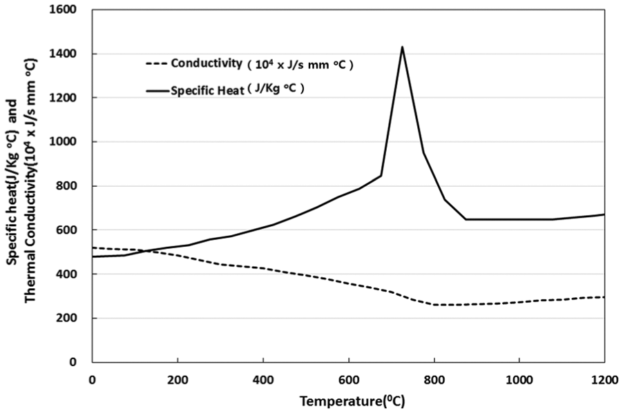
Temperature dependency of thermal properties of mild-steel and AH32-steel plates.
To solve equation (10) in this model, the ABAQUS software package was utilized. 17 The thermal histories and HAZ sizes were predicted for the analysis according to the changes in the plate thickness 12, 20, 30, and 40 mm and the plates are made of mild and AH32 steels.
Mechanical analysis
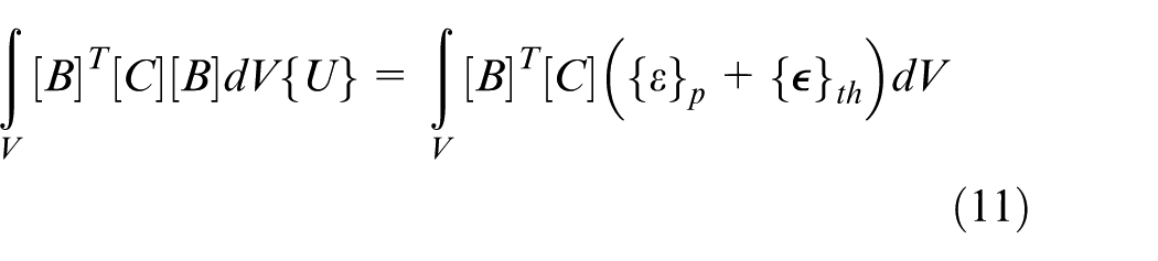
To estimate the deformation of the steel plate during the gouging process, the thermo-mechanical phenomenon of the steel plate during the process was modeled and analyzed using the numerical FEM. The process of dividing the solution domain by the finite elements was the same as that used for the thermal analysis. The governing equation for the finite element model can be presented in the following way
where
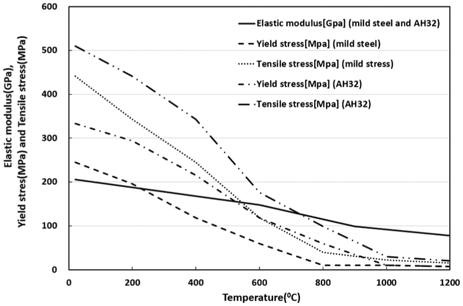
Temperature dependency of mechanical properties of mild-steel and AH32-steel plates.
Two mechanical boundary conditions, as shown in Figure 8, were used for the thermo-mechanical model. One comprised two kinds of supporters at the center and the ends of the plate widthwise to consider the effect of the stiffness of the plate during the gouging process. The other comprised the simple widthwise supporter at the center of the plate during the cooling step. 19
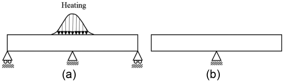
Boundary conditions during (a) heating and (b) cooling for the mechanical analysis of the finite element model.
Considering the symmetric condition of widthwise gouging on the steel plate, only half of the plate in the width direction was analyzed and the symmetric condition was enforced on the center of the plate widthwise. For the solution of equation (11), the ABAQUS software package was utilized. 17
The deformations of the steel plates during the gouging were estimated according to the change in the thicknesses of the plates (12, 20, 30, and 40 mm). The analyses were also performed to consider the effect of a change of the material whereby the mild-steel plate was replaced by the AH32-steel plate.
Experiment
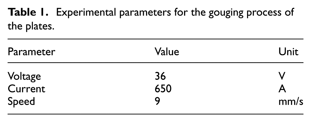
A series of the arc gouging experiments were performed with an automatic-feed torch carriage to verify the corresponding results of the models that were used for the analyses. The set-up and gouged plate of the gouging experiment are shown in Figure 9. The gouging conditions were selected as being used in shipbuilding sites and are summarized in Table 1. The gouging electrode used in this work was 11 mm in diameter.
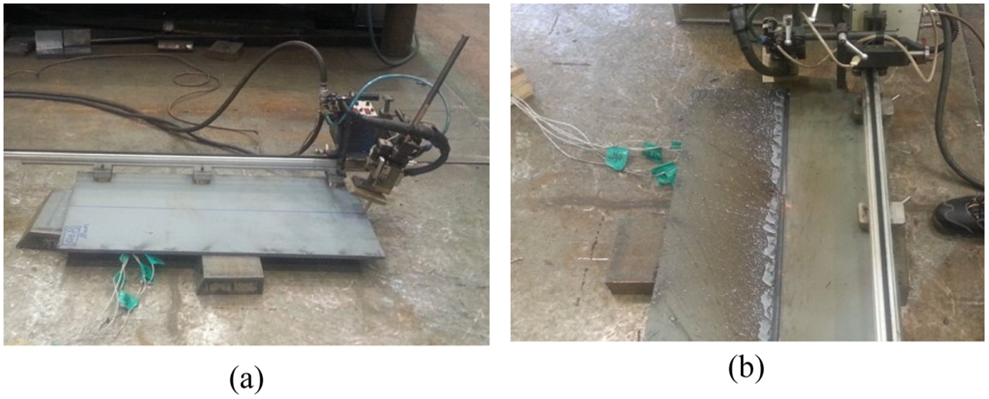
Gouging experiment: (a) set-up and (b) gouged plate.
Experimental parameters for the gouging process of the plates.
The dimensions of the plate that was used for the experiment were the same as those of the numerical model. Mild-steel plates of a 300 mm length and 240 mm width, with thickness variations of 12, 20, 30, and 40 mm, were gouged by a gouging process, and the gouged plates were cut to obtain the section that included the gouged surface and HAZ. The sections of the cut specimens were then polished and etched to show the HAZ macrostructure. The HAZ sizes from the lower part of the section to the upper part were measured for each plate according to different thicknesses. Before the cut was made to obtain the section, the angular distortion of each plate after the gouging process was measured with a three-dimensional coordinates measuring machine (CMM); additionally, the 20-mm-thick AH32 plate was gouged to compare its angular distortion afterward with that of the equivalent mild-steel plate.
Results and discussion
Thermal analyses were carried out during the gouging process for the steel plates of a variety of thicknesses 12, 20, 30, and 40 mm and the results were compared with those of experiments that sought to verify the heat source and the numerical models of the process suggested in this study. Figure 10 shows the results of the analysis with respect to the peak-temperature distribution, whereby the maximum temperature experienced at each position during the gouging process is presented adjacent to the groove of the 40-mm-thick plate, while the other side of the figure shows the result of the experiment that revealed the shape of HAZ. The two results for the thickness seemed to be fairly well matched; of especial significance, when the region heated above 723 °C is defined as HAZ, the shape of the HAZ that was obtained by the numerical analysis along the edge of the gouged surface is in sound agreement with that measured in the experiment. The heat-source model that was developed from the Rosenthal equation is therefore considered to be an appropriate model for the gouging process, and the numerical model suggested in this study is a feasible tool for the prediction of the temperature distribution throughout a steel plate during the gouging process.
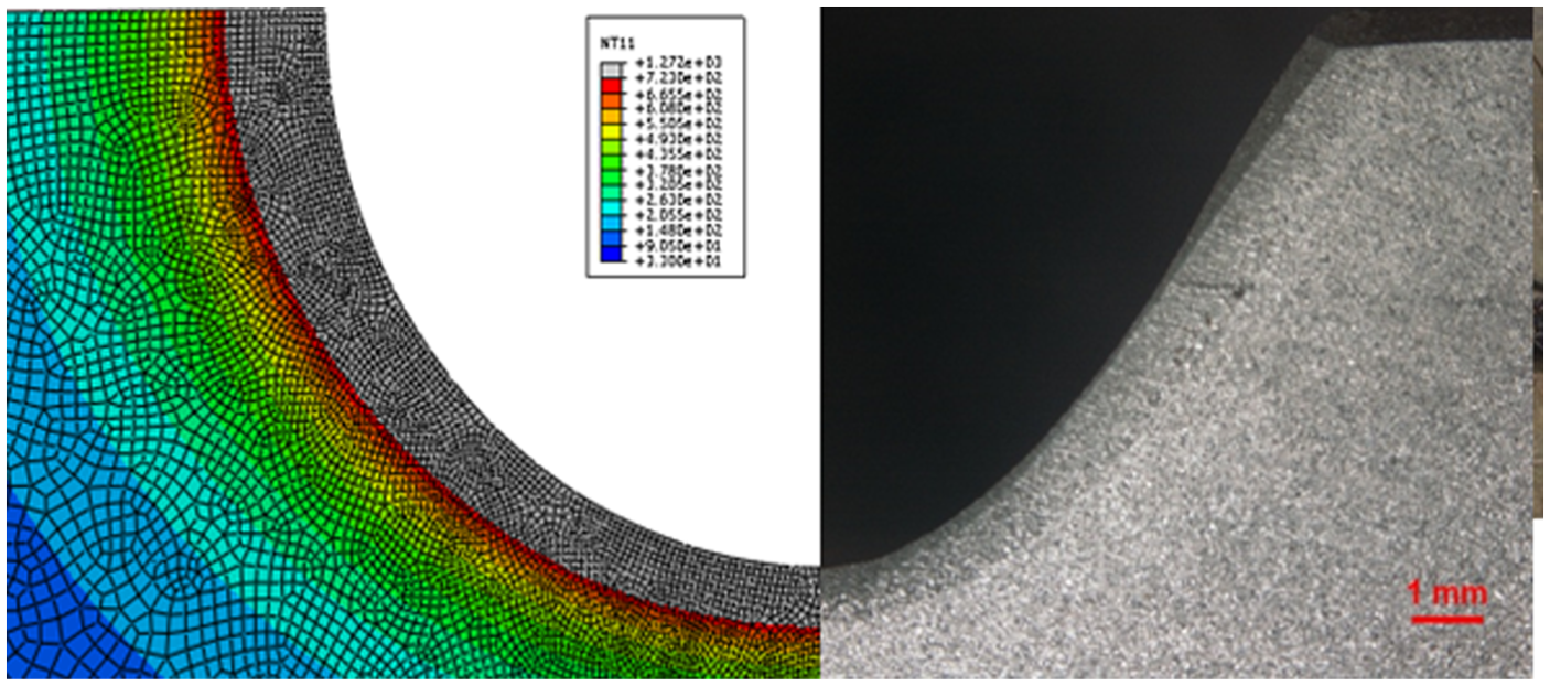
Comparison between predicted HAZ size and experimental one of 40-mm-thick plate.
Figure 11 shows the quantitative size of HAZ along the gouged surface from the lower position to the upper position. In the figure, the HAZ sizes that were predicted using the thermal analysis for the steel plates with thicknesses of 12, 20, 30, and 40 mm are compared with those obtained by the gouging experiments for steel plates of the same thicknesses. The predicted result shows that the size of HAZ is progressively widened from approximately 0.8 mm at the lower position to approximately 1.4 mm at the upper surface in a similar manner for each thickness; therefore, it is notable that the HAZ size remains nearly constant even though the thickness of the plate changes during the gouging process. The measured results also show that the HAZ sizes are widened from the region of approximately 0.5–0.7 mm at the lower position to the region of approximately 1.2–1.6 mm at the upper surface, with somewhat different size increments for each thickness. It is believed that this slight difference of HAZ size according to the thickness of the plate is derived from the discontinuous, periodic blowing away of the molten metal from the base metal, which was not considered in the model.
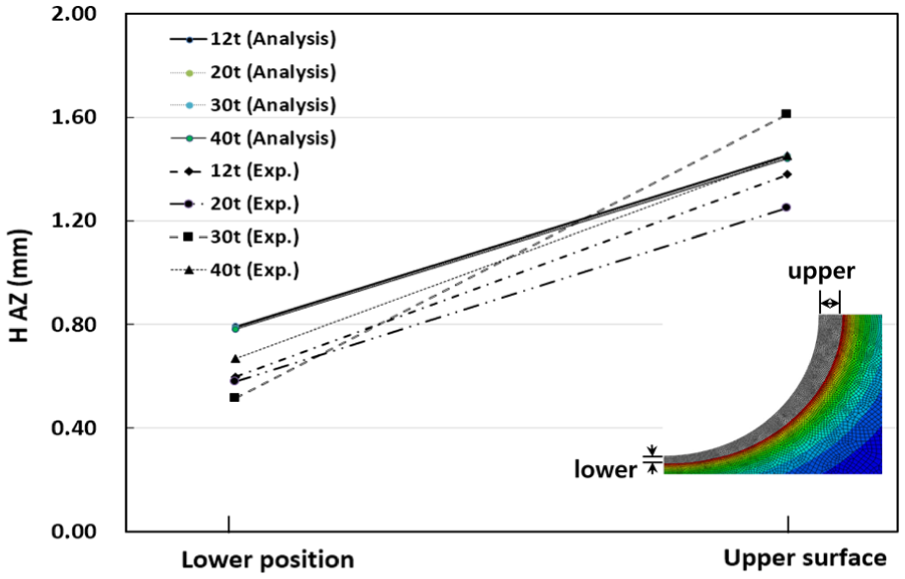
Comparison of predicted HAZ sizes with those obtained by experiments, from lower to upper position, along the gouged surfaces of various thicknesses.
The thermo-mechanical analysis of the FEM model was then performed using the results of the thermal analyses. Angular distortions were predicted by the thermo-mechanical analysis for the mild-steel plates of 20, 30, and 40 mm thicknesses. The predicted distortions with the analysis are presented in Figure 12 after they were compared with those obtained by the experiments. For the 20-mm-thick plate, the maximum deformation was approximately 1.6 mm at the edge of the plate widthwise. The deformation began to decrease to approximately 0.7 mm when the thickness increased to 30 mm because the stiffness becomes obviously larger when the thickness is increased to resist the angular deformation; the deformation decreased to approximately 0.3 mm when the thickness was 40 mm. Although the predicted deformations were somewhat lower than the measured results, the two results were fairly well matched for each plate thickness; therefore, it is feasible to use the thermo-mechanical model to analyze the mechanical behavior of the steel plate during the gouging process.
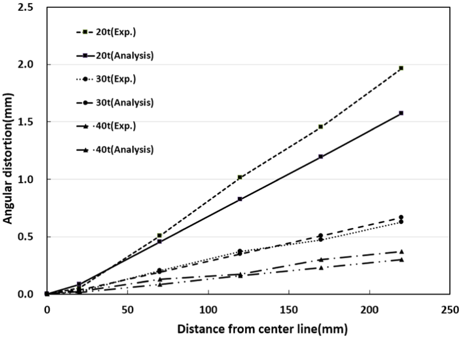
Comparison of predicted angular distortions with those obtained from the experiments with a variety of plate thicknesses.
When the material of the analysis was changed to AH32 for the plate of a 20 mm thickness, the maximum angular distortion was predicted to decrease to approximately 1.25 mm from approximately 1.6 mm, as shown in Figure 13; this seems to be due to the greater stiffness of the AH32, when compared to that of the mild steel, as shown in Figure 7. The experimental results also show that the distortion that was obtained for the AH32 plate is smaller than that of the mild-steel plate.
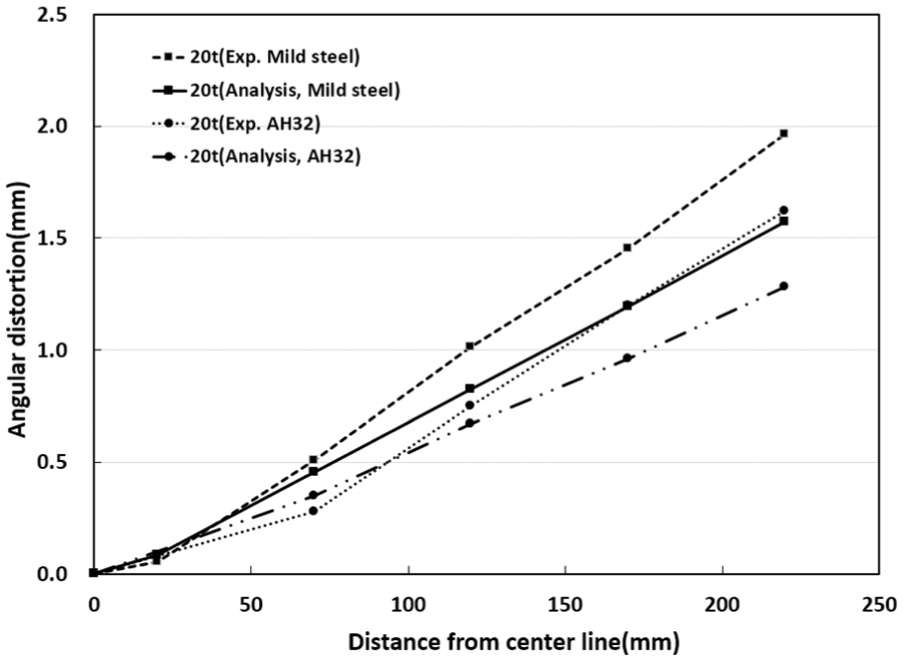
Comparison of the angular distortion of mild steel that resulted from arc gouging with that of AH32.
Conclusion
To study the effect of the gouging process on the welding distortion of thicker plates that are prepared with an X-shaped groove using a numerical simulation, the heat-source model of the gouging process was first proposed based on an analytical solution; a thermo-elasto-plastic model of the process was then developed and analyzed using a numerical FEM. To verify the thermal analysis that was performed with the models, the predicted HAZ sizes were compared with those measured by experiment and they are fairly well matched. In addition, the angular distortions of the plates that were predicted by the numerical analyses are also in a sound agreement with those measured by experiment, showing that both results indicate that the angular distortion is significantly affected by the thickness of the plate.
Through a series of analyses and comparisons, the proposed heat-source model is believed to be appropriate for an efficient and effective simulation of the gouging process due to the analytic characteristics of the time and memory saving in the subsequent thermo-mechanical analyses. It would be feasible to use the thermo-mechanical model with the heat-source model to predict the welding distortions of thick steel plate, including during the gouging process. The findings of this study would also be useful for further studies to increase the accuracy in prediction of welding deformations of thick steel plates.
Footnotes
Declaration of conflicting interests
The author(s) declared no potential conflicts of interest with respect to the research, authorship, and/or publication of this article.
Funding
The author(s) disclosed receipt of the following financial support for the research, authorship, and/or publication of this article: The authors would like to thank Samsung Heavy Industries, Co., Ltd, for supporting this research.