
Abstract
Measuring and evaluating geometric errors of an aero-engine blade are a complex research topic. At present, there is not a uniform evaluation criterion and completed strategy in the blade manufacturing industry. This article proposes an effective strategy for measuring and evaluating geometric errors of an aero-engine blade: first, measuring six feature curves and calculating the coordinate transformation value with singular value decomposition to improve the accuracy of blade localization; then, an improved measurement method based on the model offset is introduced to eliminate probe radius compensation errors. Finally, the geometric errors of blade are evaluated using the collected measurement data based on genetic algorithm, and a practical evaluation criterion is provided. The proposed strategy for two aero-engine blades has been performed to demonstrate the effectiveness of the proposed methodology and show that it can prevent false feedback for the underlying manufacturing process for aero-engine blades.
Introduction
The aero-engine blades are designed with extremely strict tolerances in order to ensure efficient energy conversion under the strained operation conditions. Therefore, all manufactured blades must be accurately inspected and evaluated for the sake of conformance to the specified tolerances. Any inaccuracy in evaluating the associated geometric errors may lead to false feedback for the underlying manufacturing process for aero-engine blades. And the geometric errors of blades play an extremely important role in the aerodynamic performance of aircraft engine. So, it is important to develop a correct and effective evaluation method for evaluating correctly geometric errors of aero-engine blades.1,2
Generally, localization and measurement are two key problems in blade evaluation. The accuracy of measurement data affects directly on the result of blade evaluation. Therefore, a blade must be located accurately before measuring for the purpose of obtaining high-quality measurement data. Nowadays, there are many researches about localization and measurement. Documents of Besl 3 apply first the iterative closest point (ICP) algorithm to point cloud registration, which can availably improve the efficiency of registration. And literatures of Jiang 4 discussed deeply the registration for precision localization of free-form surface. Zhu et al. 5 discussed various techniques that accelerated the registration process. Amberg et al. 6 proposed optimal algorithms for surface registration. However, their work about registration and localization concentrated on how to improve the versatility of the algorithm but increased complexity and time cost. And in terms of measurement, the non-contact three-dimensional (3D) scanners and coordinate measuring machines (CMMs) have been widely applied on blade measurement in the industry.7,8 With the advantage of high speed and the advance on laser technologies, non-contact 3D scanners have been successfully applied on surface data acquisition in reverse engineering. However, laser inspection data are affected by many factors such as part materials, environment, the color of parts, and surface roughness. The measurement data also need to be post-processed before being further used. Sun and Li 9 presented the application of laser displacement sensor in aero-engine blade measurement; it has the thinner structure and higher efficiency than the CMMs. But because of the improvement of inspection accuracy, more and more purchasers prefer using CMM equipped with touch-trigger probes to measure aero-engine blades. There are many researches concentrated on blade measurement with touch-trigger probes.10–12 And they discussed some problems about probe radius compensation and measurement path planning.
After accurate localization and measurement, geometric errors of an aero-engine blade can be evaluated correctly. Given the sectional inspection data points, Hsu et al. 13 proposed to best match the set of discrete data points for each airfoil section onto the corresponding airfoil computer-aided design (CAD) profile. The displacement and rotation errors of an airfoil section were then concurrently evaluated. Li et al. 14 presented a calculation method of twist error of aero-engine blade based on measuring data of CMM. Cheng et al. 15 make a clear analysis of blade blending and torsion deformation, which can become a basis of evaluation. Khameneifar and Feng 16 presented a tolerance evaluation approach based on the reconstruction of the airfoil profile. The position error was isolated from the orientation errors so as to resolve the coupling problem of the existing method. However, these studies above just make local study of measuring and evaluating blade geometry. There is not an efficient evaluation criterion and a completed strategy for measuring and evaluating blade geometric errors.
This article presents a completed strategy for measuring and evaluating blade geometric errors based on genetic algorithm (GA). It aims to provide an effective and correct method of blade evaluation so as to decrease false feedback for correcting the involved blade manufacturing operations. The flowchart of the proposed strategy is illustrated in Figure 1, and it is organized as follows. In the “Blade localization” section, the methodology of blade localization is described, including feature curve measurement and localization results based on singular value decomposition (SVD). The “Improved method of measurement” section presents an improved measurement method, which can eliminate the compensation errors of probe radius. The “Calculation and evaluation” section illustrates a mathematical model of blade evaluation with regional tolerance constraint and provides a solving solution of this model based on GA. The “Experiment results” section illustrates the experimental verification of the proposed strategy. Finally, the “Conclusion and future work” section concludes this article.
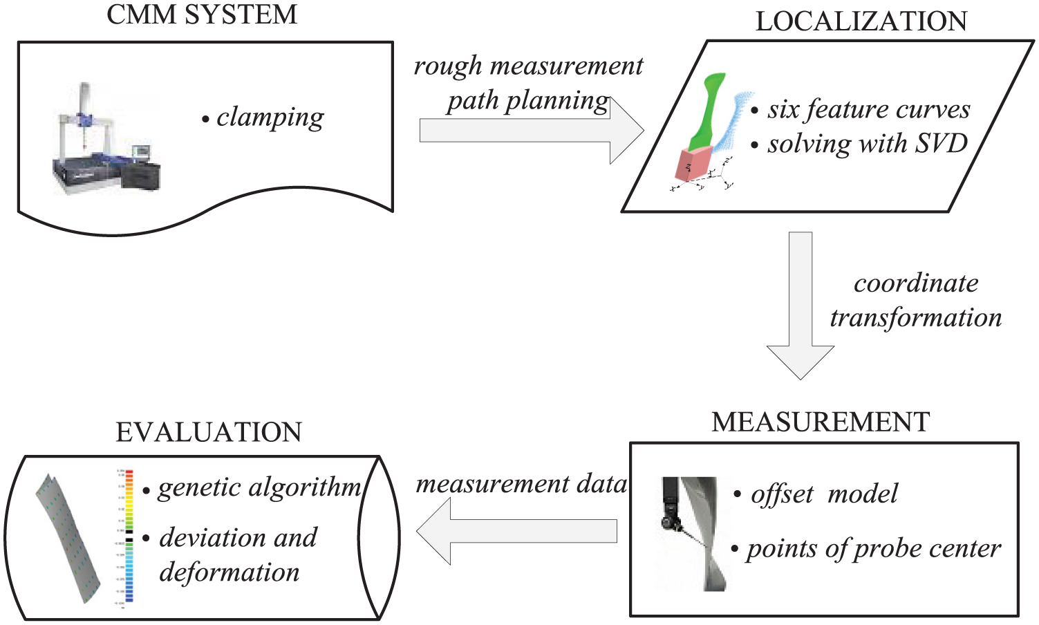
The strategy for measuring and evaluating geometric error of blade.
Blade localization
Inevitably, there are some displacement and rotation errors between measurement points and the corresponding CAD model due to the misalignment of respective coordinate system. It is necessary for blade localization to obtain the displacement and rotation errors before measured. And therefore, the reliable alignment between measurement data of blade and its CAD model is urgent to achieve precise localization.
There are many researches on measurement path planning of blades in literatures of Obeidat and Raman,
11
Yu et al.,
12
Li et al.,
17
and Jiang et al.
18
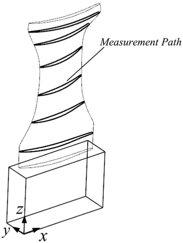
And in this article, six curves specifically are selected as the measurement paths shown in Figure 2. And accordingly,
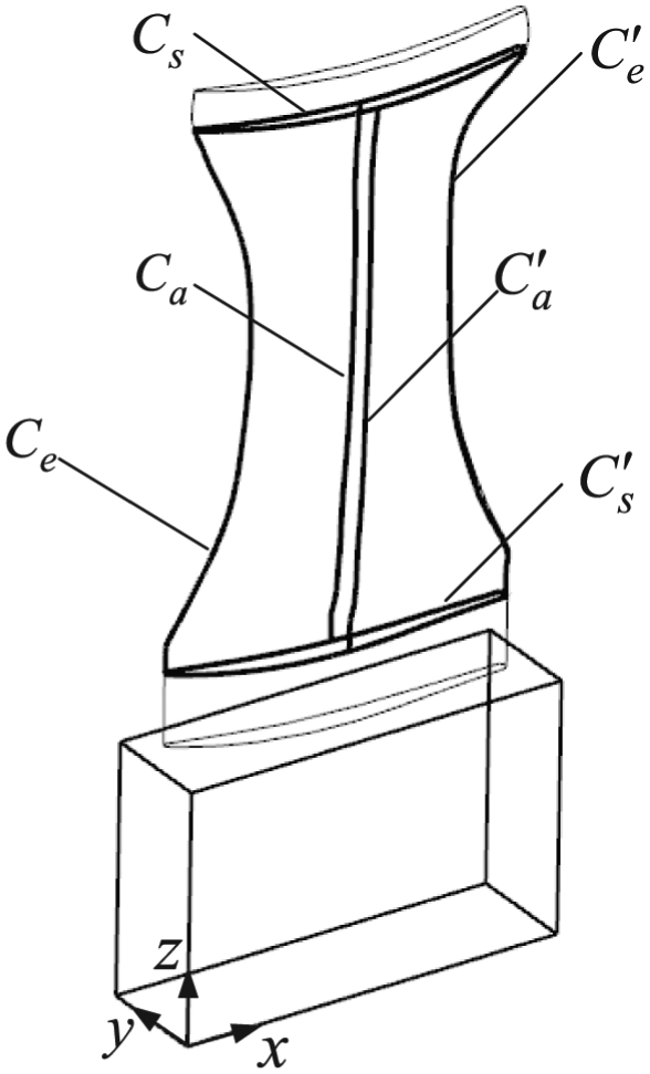
Measurement paths of blade localization.
Given the pair of point
Mathematically, matrix
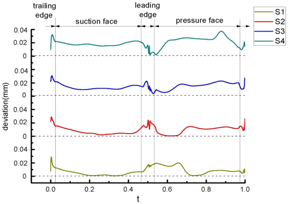
To illustrate the effectiveness of the proposed method for blade localization, a compressor blade machined by grinding is measured by CMM equipped with touch-trigger probes. The deviations of measurement points on six feature curves are shown in Figure 3(a). Localization transformation parameters
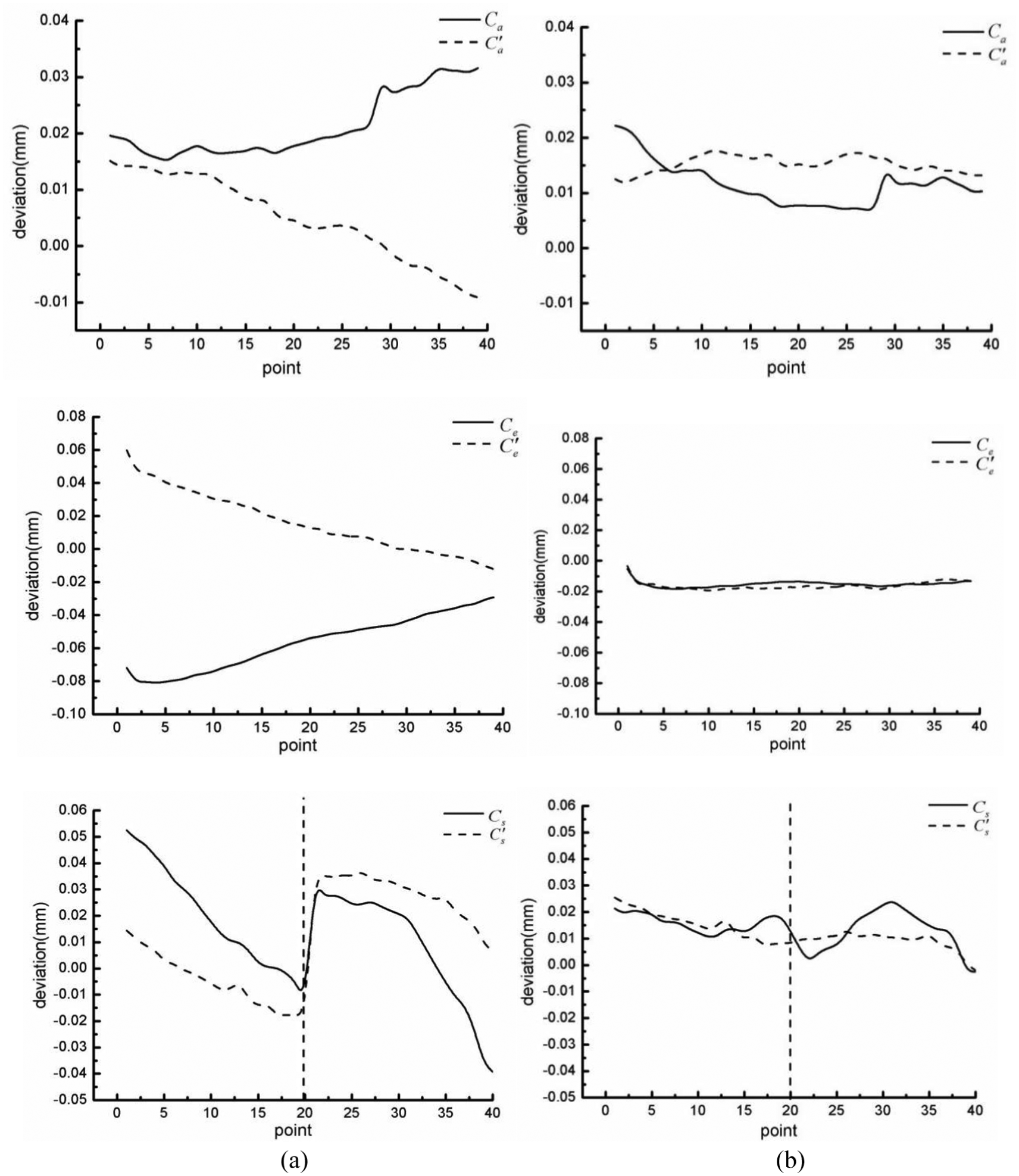
The diagram of deviation comparison: (a) before localization and (b) after localization.
Improved method of measurement
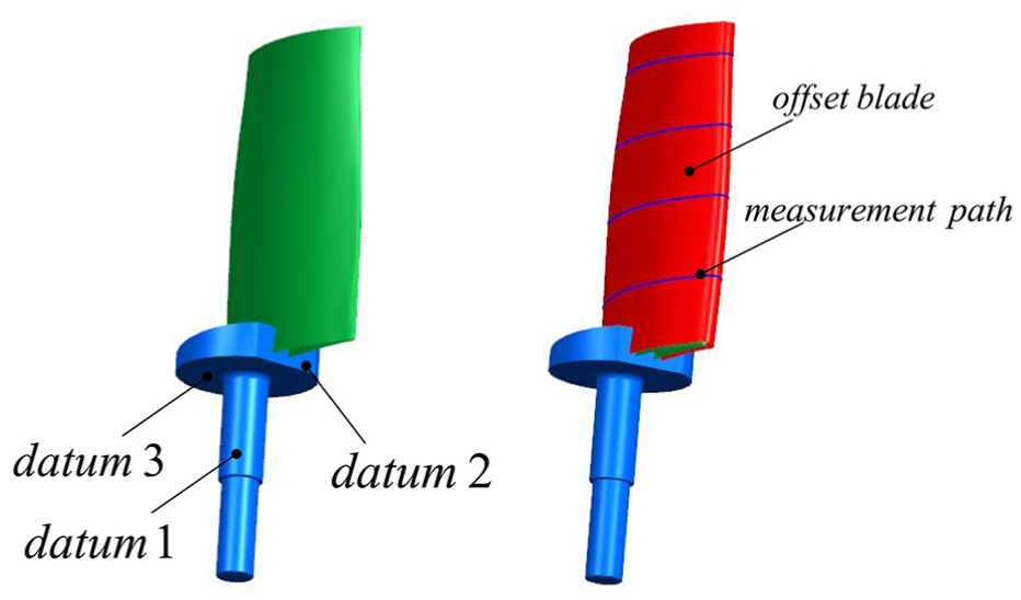
In practice, the surface of a blade is measured section-by-section in engineering. As shown in Figure 4, measurement paths of a blade are cross-sectional curves which provided by designer, and the theoretical sampling points can be generated in the measurement system. However, because of the geometric errors caused by the deformation, there will be an offset between the actual measured points and the theoretical points collected in the measurement system. Furthermore, this deformation of a blade has a bad effect on the normal direction of the blade surface at the contact point. And mistaken normal direction will cause the probe radius compensation errors. To eliminate this compensation error, this article proposed a simple and effective measurement method based on offset model.
Blade measuring planning paths.
A theoretical offset blade surface

where r represents probe radius and
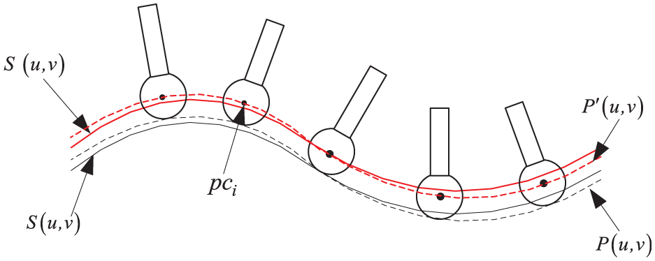
Measurement schematic diagram based on offset model.
Generally, the Z coordinate values of sampling points on one cross-sectional curve are invariable theoretically. However, as shown in Figure 6, the geometric deformation of a blade will bring about that the Z coordinate value of the collected probe center
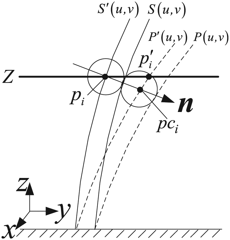
Deformation analysis for blade measurement.
Calculation and evaluation
Best fitting based on GA
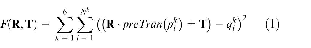
After localization, the measurement points can be obtained based on the method introduced in the “Improved method of measurement” section. And the geometric errors of blades can accurately be evaluated using the measurement points and the corresponding CAD model. Generally, the design tolerance of blade edges is different from the areas of blade body, so the tolerance constraints must be considered in the least-squares problem. It is described as equation (3)
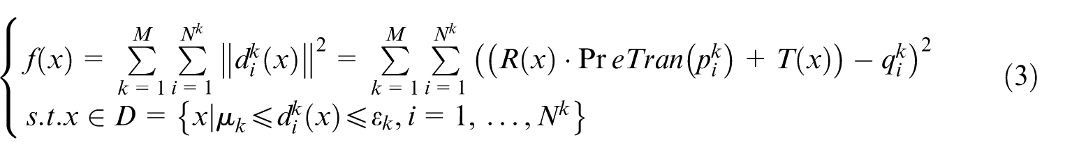
where
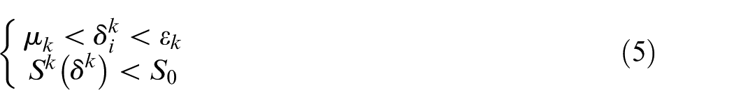
In this article, because of better favorable and accuracy, the GA is used to solve this problem. And as a global optimization algorithm, GA has been applied in many engineering practices. First, an initial solution

where N is the number of points beyond tolerance constraint and M represents the total number of measurement points. Obviously,
The solving process is illustrated in Figure 7. The selection of parameters in GA directly affects the accuracy of the solving result. A set of reasonable parameters are obtained by multiple tests with the MATLAB GA toolbox.
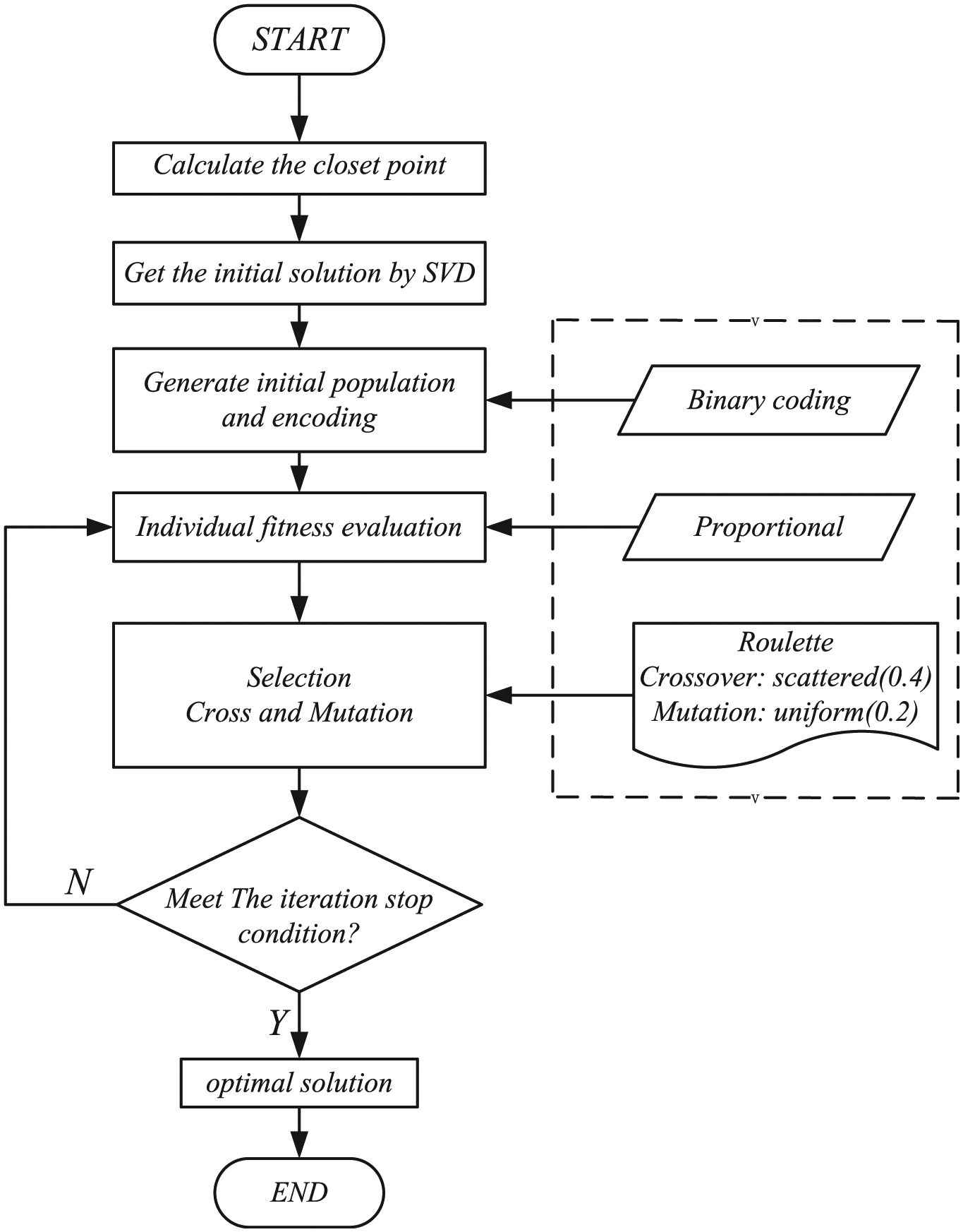
The flowchart of genetic algorithm.
In order to demonstrate the validity of the proposed methodology, a typical blade is simulated to validate it. The tolerance of blade edge ranges from −0.04 to 0.04 mm, while blade body from −0.04 to 0.07 mm. The number of measurement points is 105. And the theoretical transformation value is
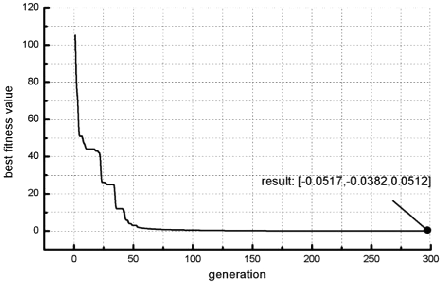
Result of solution based on genetic algorithm.
A comparison of ICP without considering constraint condition is listed in Table 1. According to Table 1, the two transformation values
The comparison of results between ICP and GA.
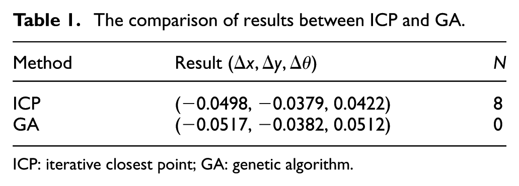
ICP: iterative closest point; GA: genetic algorithm.
Evaluation criterion
Actually, profile deviation can be calculated with the distance of point
where
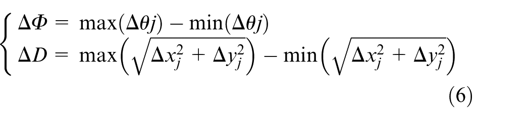
where j represents measurement cross-sectional curves.
Experiment results
The developed measurement and evaluation strategy for two aero-engine blades is verified to show its validity compared with the existing methodology in engineering practice.
Example 1
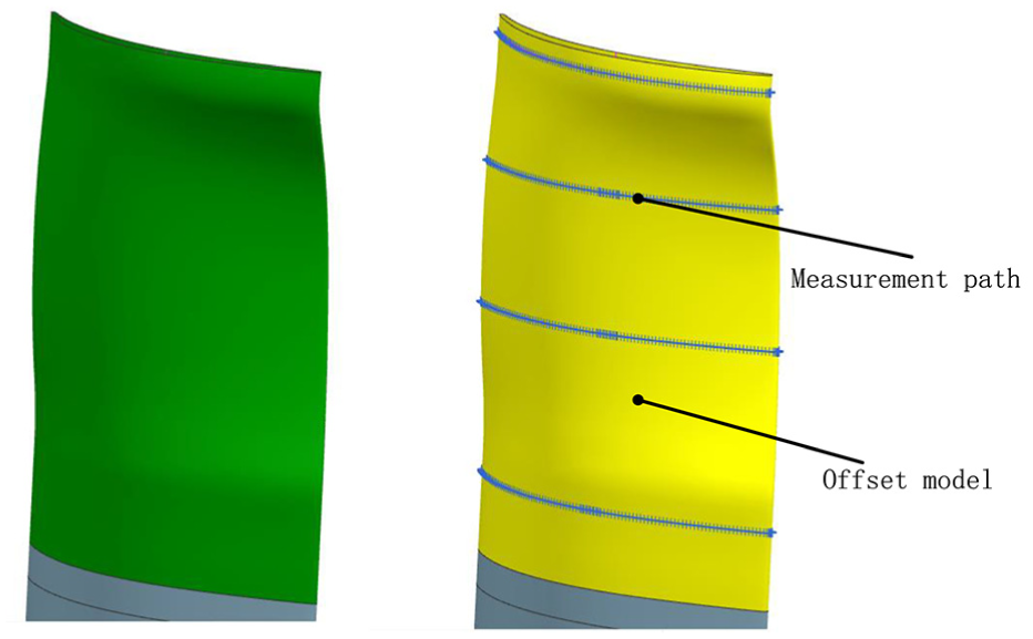
The experimental blade was machined by grinding, and digital model of this blade is shown in Figure 9(a). The blade was measured with three CMMs shown in Figure 10.
Digital model and measurement model.
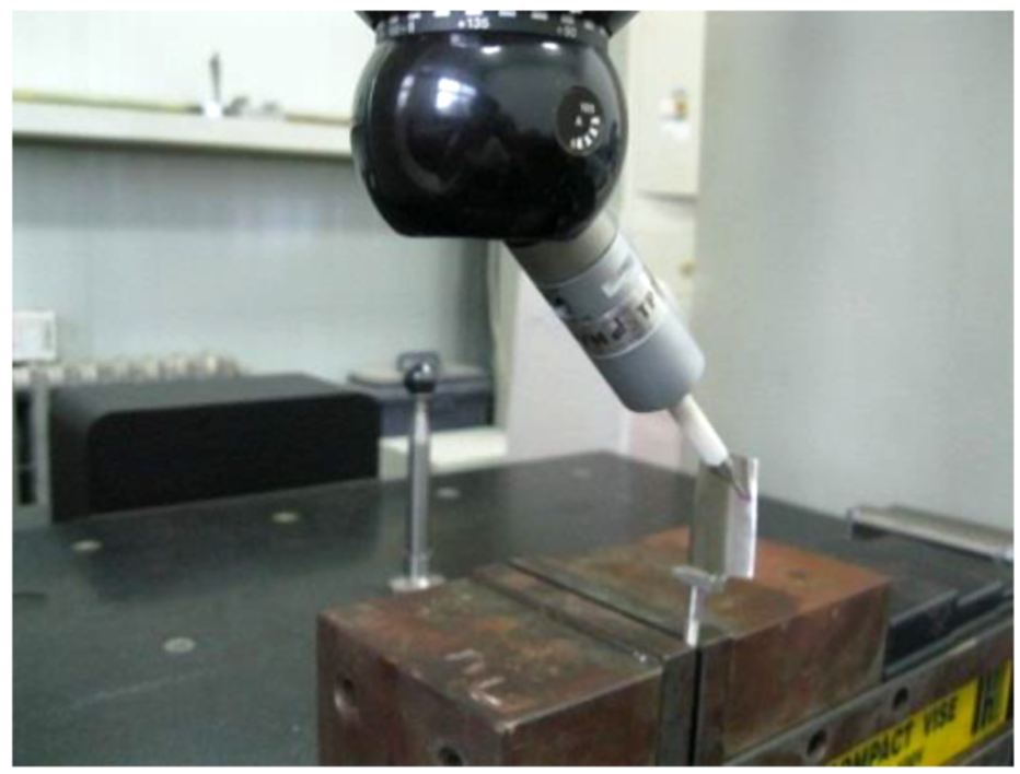
Process of measuring using CMM.
The radius of touch-trigger probe installed on CMM is 1 mm. And the profile tolerance of blade edge ranges from −0.04 to 0.04 mm, while blade body from −0.05 to 0.05 mm. The position tolerance is ±0.2 mm and the orientation tolerance is ±0.3°.
The proposed method will be implemented in accordance with the following process. First, the offset blade model is established in a 3D modeling software (Unigraphics NX), and the measurement path is shown in Figure 9(b). Second, six feature curves are measured, and the result of blade localization is
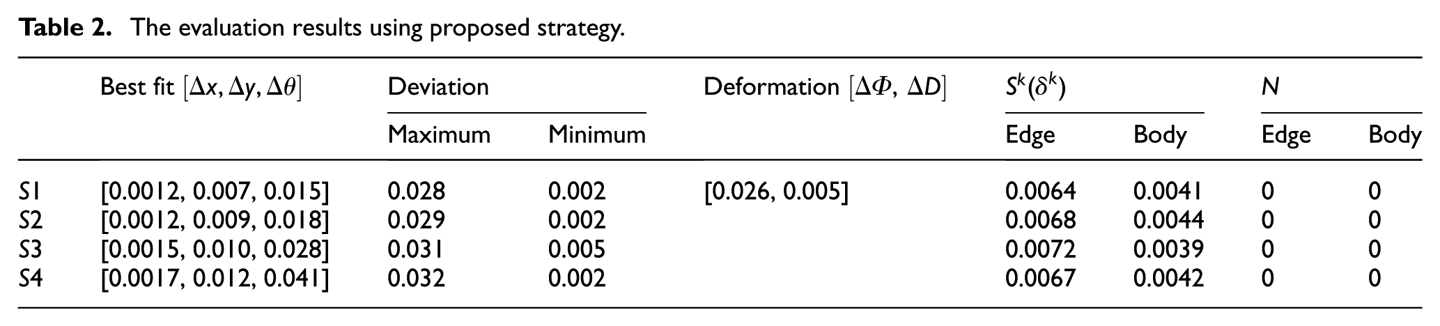
The evaluation results using proposed strategy.
Deviation of section-cross curves.
Obviously, according to Table 2, the number of points beyond tolerance is zero, and both the position and orientation errors are within the given tolerance. From Figure 11, the profile errors of blade also meet the requirement of design tolerance. Therefore, this experiment blade can be evaluated that it is a qualified blade.
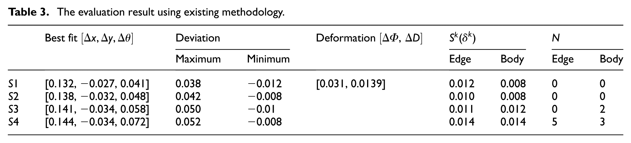
However, in engineering practice, this experiment blade is measured and evaluated using the existing methodology, and this methodology is described as follows: (1) blade localization: the traditional 3-2-1 mode, (2) measurement: probe radius compensation based on the theoretical normal of CAD model, and (3) evaluation: using the ICP algorithm without considering the tolerance constraint. The evaluation result is listed in Table 3. From Table 3, there are 10 points beyond tolerance and both the position and orientation errors are evidently greater than the result in proposed method. The evaluation result using the existing methodology shows that the blade is unqualified.
The evaluation result using existing methodology.
Example 2
The second experimental blade was machined by computer numeral control (CNC) polishing, and digital model of this blade is shown in Figure 12. The profile tolerance of blade ranges from −0.02 to 0.05 mm. The position tolerance is ±0.1 mm and the orientation tolerance is ±0.17 mm. In this example, two sets of measurement data after polishing this blade are analyzed according to the procedure used in example 1.
Digital model and measurement model.
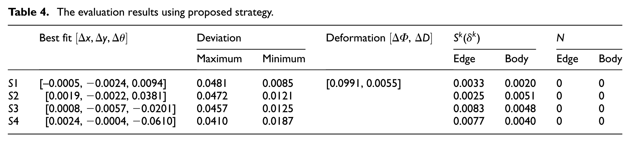
For the first set of data, the blade is separately evaluated by the proposed strategy and the existing methodology. Table 4 shows the evaluation results using proposed strategy, and Table 5 shows the evaluation result using existing methodology.
The evaluation results using proposed strategy.
The evaluation result using existing methodology.
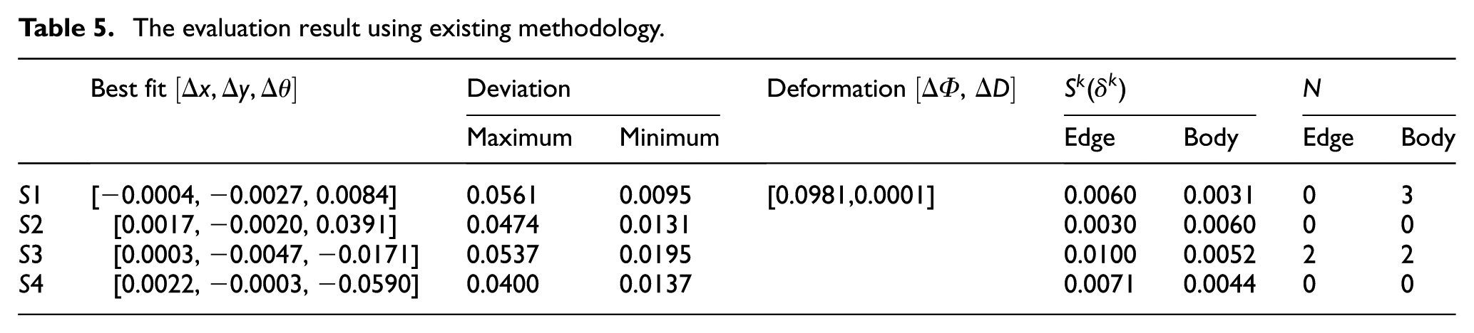
Obviously, from Tables 4 and 5, both the position and orientation errors are within the given tolerance using the two methods. However, there are no points out of tolerance using proposed strategy, and the number of points beyond tolerance is seven using existing methodology. Therefore, this polishing result of experimental blade will be evaluated that it is unqualified using existing methodology due to these points beyond tolerance. But according to the proposed strategy, this blade can be considered qualified.
For the second set of data, the blade is also separately evaluated by the proposed strategy and the existing methodology. The evaluation results of the two methods separately are shown in Tables 6 and 7.
The evaluation results using proposed strategy.

The evaluation result using existing methodology.
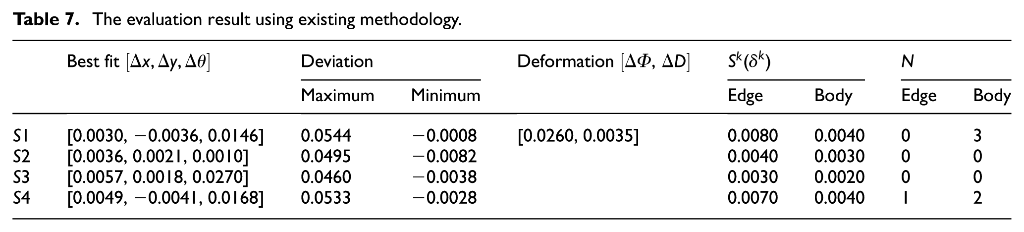
In Table 6, the number of points beyond tolerance is 2, and in Table 7, the number of points beyond tolerance is 6. By comparing Tables 6 and 7, the number of points beyond tolerance is reduced from 6 to 2 using proposed strategy, and both the position and orientation errors are within the given tolerance.
According to these experiment examples above, obviously, the global profile errors of proposed strategy slightly less than that of existing methodology. The reasons for this situation should include inaccurate localization and probe radius compensation errors in existing methodology. Maybe the transformation value will increase compared with existing methodology, but the position and orientation errors are within the design tolerance. Furthermore, the number of points beyond tolerance mostly is zero or visibly less than that of existing methodology. And the number of points beyond tolerance largely affects evaluation results of blade. Consequently, though the relatively low efficiency, the proposed strategy performs more reliable in evaluating geometric errors of blades considering tolerance constraint when compared with existing methodology. And it can prevent false feedback for the underlying manufacturing process for aero-engine blades.
Conclusion and future work
Measuring and evaluating geometric errors of an aero-engine blade are a complex research topic. At present, there is not an efficient evaluation criterion and a completed strategy for measuring and evaluating blade geometric errors. Therefore, in this article, a systematic strategy for measuring and evaluating geometric errors of aero-engine blades was developed. The main advantage of this strategy is that proposing a systematic procedure supported with precise localization, improved measurement, and effective evaluation, and a practical evaluation criterion was provided in the end. Superior to existing method, the experiment results show that our strategy can effectively evaluate geometric errors of aero-engine blades and prevent false feedback for correcting the involved manufacturing operations.
Under the framework of the proposed strategy, future work will be conducted in the data reduction of measurement points and sections for aero-engine blades. And to establish a more rational evaluation criterion with less measurement data is also an important research topic in the future. The authors plan to concentrate on the measurement data reduction, and try to answer the following two questions:
Which cross-sections should be measured on the profile of blade?
Which points should be measured on each sectional curve?
Footnotes
Declaration of conflicting interests
The author(s) declared no potential conflicts of interest with respect to the research, authorship and/or publication of this article.
Funding
The author(s) disclosed receipt of the following financial support for the research, authorship, and/or publication of this article: The work is supported by National Science and Technology Major Project (Grant Number 2018ZX04004001).