
Abstract
The aim of this article is to provide an introduction and overview of recent advances in the key technologies and the supporting computerized systems and to indicate the trend of research and development in the area of computational numerical control machining. Three main themes of recent research in computer numerical control machining are simulation, optimization and automation, which form the key aspects of intelligent manufacturing in the digital- and knowledge-based manufacturing era. As the information and knowledge carrier, feature is the efficacious way to achieve intelligent manufacturing. From the regular-shaped feature to freeform surface feature (FSF), the feature technology has been used in manufacturing of complex parts, such as aircraft structural parts. The authors’ latest research in intelligent machining is presented through a new concept of multi-perspective dynamic feature, for future discussion and communication with readers of this special issue. The multi-perspective dynamic feature concept has been implemented and tested in real examples from the aerospace industry and has the potential to make promising impact on the future research in the new paradigm of intelligent machining. The authors of this article are the guest editors of this special issue on computational numerical control machining. The guest editors have extensive and complementary experiences in both academia and industry, gained in China, United States, and United Kingdom.
Keywords
Introduction
With conventional computer-aided “x” (CAx) technologies, including computer-aided design (CAD), computer-aided manufacturing (CAM), computer-aided engineering (CAE), computer-aided process planning (CAPP), and computer numerical control (CNC) in a more general sense, computerized programs serve the role of providing assistance while engineering users are responsible for making process decisions. CAx systems produce process data (including product definitions, manufacturing process plans, cutting tool paths, and control commands) based on users’ inputs. Although reliable results are produced, the degree of efficiency depends on the users providing process parameters. In recent years, the advances in computational power, algorithms, and better understanding of the physics and mathematical models of machining processes enabled computerized programs to automate some of the process decisions. The goal is to automate and optimize, as much as possible, the process decisions traditionally taken by engineers. These technologies would eventually make the users more productive and the machining processes more efficient and optimized.
This article reports on state-of-the-art research in computerized intelligence, including automated decision-making and optimization, related to numerical control (NC) machining processes. As suggested in the title, the code name “intelligent machining” is adopted to represent such computerized intelligence in machining processes. Computerized intelligence involves algorithm design, knowledge-based engineering, and computation activities. The scope of this article is limited to aspects related to part machining covering most (but not all) of the contemporary interests. This article is not intended to be a historical review, but focus on recent trends, while some earlier publications were cited to provide contextual background. The reference list may leave out important (and older) articles that are corner stones of the topics. Section “Advances in CNC machining technologies” of this article provides an overview of advances in recent research from a specialized “technology” point of view, while section “Advances in CNC machining systems” provides review of research from an integrated “systems” point of view. The authors’ proposed dynamic feature concept and latest research in intelligent machining are presented in section “A multi-perspective dynamic feature concept for intelligent machining,” to share with readers of this special issue and to encourage further discussions and communications in this topic.
Advances in CNC machining technologies
This section reviews and introduces specific key technologies in the area of computational numerical control. Each sub-section describes recent progress on computerized intelligence in a particular topic and provides citations of relevant research articles for further information.
Work step planning and optimization
Before the programming and execution of every machining operation (work step), it requires planning for the process operational conditions. The planning tasks include the selection of machine tools, cutters, and setup configurations. The decisions are made by experienced operators/engineers based on the existing resources/equipment in the shop floor. While the operators/engineers try to come up with best decisions, the results are not guaranteed to be optimal if the workers are not well trained, not given proper information, nor time to perform. Recent research attempted to perform some of the work step planning tasks with machine intelligence. The goal is to formulate the planning tasks as optimization problems that can be solved mathematically and numerically. This would enable automated solutions for work step planning, replacing some of the human decision-making tasks.
Setup planning involves making a lot of decisions such as the location and orientation of the workpiece on the machine table, the (clamping) positions of the fixtures to the workpiece, and the selection of fixtures. Setup configuration tasks can be automated based on various optimization criteria, including global avoidance during machining, 1 machine kinematic efficiency, 2 machine kinematic–induced tracking errors, 3 and clamping force–based spatial arrangement of fixtures. 4 Cutter (tool) selection is another important task of work step planning. There are several factors to be considered for cutter selection. Among them are the size (radius) of the cutter for fitting into narrow regions (accessibility) 5 and cutting profile (at the bottom of the cutter) for fitting workpiece surface concavity (curvature).6,7
Optimal tool-axis computation
When programming five-axis tool paths, the specification of tool-axis control is the most difficult task. The rotational motions are difficult to visualize and process mathematically. The fact that the workpiece and work table on the machine tool may rotate in some systems presents additional difficulty for the programmers to fully comprehend. There are two types of five-axis milling: point and flank. Point milling uses the tip (bottom) of the cutters to remove the material, while flank milling, also known as profile cutting and peripheral milling, uses the side of the cutter to remove material. There are several key requirements to consider for tool-axis programming, as explained below:
Collision avoidance. The programmed tool-axis orientation shall never cause the cutter head to collide with any obstacles in the machine tool. This applies to both point and flank milling.
Shape accuracy. When the cutter orientation affects the amount of material to be removed, the overcut and undercut must be controlled. This applies mainly to flank milling.
Cutting condition. Tool-axis determines the orientation of the cutter relative to the workpiece surface, hence influencing the physical interaction between the cutter and the material. This applies mainly to point milling.
Machine kinematics/dynamics. The change in tool-axis is controlled by the two rotary axes. It is important to consider the kinematic limits and dynamic stability of the rotary axes in tool-axis computation. This applies to both point and flank milling.
In state-of-the-art CAM systems, the tool-axis is specified according to the given spatial descriptions. The system provides many methods and the programmers choose one among them to describe the spatial definition of the tool-axis. The methods have no direct correlation to machining requirements so the programmer has to mentally work out the results and figure out which one is the best according to the requirements. It requires high-level understanding of the mathematics and geometry, plus many years of experiences in five-axis machining. Recently, researchers began to compute the optimal orientation and positioning of tool-axis based on one or more of the above-mentioned requirements, in lieu of user-controlled spatial specifications. The efforts are mainly for flank milling, with different constraints and optimization goals.8,9
Path shape optimization
Tool path computation consists of mathematical models and algorithms, and the resulting tool paths depend on the limitations and characteristics of the computation methods. In reality, the “perfect” algorithm for tool path generation does not exist. Consequently, the tool paths usually do not meet the highest quality demands and are further degraded by the common practice of G-code representation. As a result, the tool paths generated by today’s leading commercial CAM systems suffer from several common deficiencies, such as the following:
Sudden change in direction caused by the algorithm of pattern computation.
Noisy and even jagged paths caused by geometry discretization or numerical instability.
Built-in G1 (tangent) discontinuity as a consequence of G01 (GOTO) code.
Inconsistency among neighboring passes, due to the fact that the paths are usually computed one pass at a time without considering the neighboring passes.
The goal of path shape optimization is to handle the above problems. The typical strategy is to modify the tool path shape after the tool paths are generated from the CAM systems, in either the post-processing stage (after CAM before CNC) or within the CNC during axis command processing (also known as control interpolation). Due to the fact that the post modification is performed without knowing the original part geometry, the modification must be limited to minor deviations (meaning the deviations are within the specified machining tolerance) from the given tool paths.
One type of path shape optimization solution is to perform smoothing and B-spline or non-uniform rational B-spline (NURBS) fitting on the G01 code, to achieve continuous path trajectories and hence smooth surface finish and less speed fluctuation during machining. In the case of five-axis machining, it is common to represent a tool path with dual B-spline curves, one tracking the tool-end (bottom) point and the other tracking the upper end of the cutter. Examples were given by Yuen et al. 10 for five-axis machining and Chen et al. 11 for three-axis machining. Another type of path optimization solution is to perform corner rounding of the poly-line trajectories of G01. The deviations are confined to the neighborhood of each G01 points. Examples were given by Beudaert et al. 12 for five-axis machining and Zhao et al. 13 for three-axis machining.
Although the path modification is usually performed after the path generation, it can be applied during the generation. The modification is localized, that is, applied to nearby GOTO points, during the path computation. Bouard et al. 14 applied localized smoothing to two-dimensional (2D), three-axis machining, while Beudaert et al. 15 applied localized smoothing to tool-axis, both during tool path generation.
Net shape simulation
Optimization of tool paths requires the computation of the net shape of the workpiece after the material has been removed by the cutter. The geometric net shape simulation is used to derive surface quality and volume removal rate. The former is important for finishing operation optimization, while the latter is the key to optimizing the material removal rate of roughing operations. Net shape simulation has two competing (and contradicting) requirements: accuracy and speed of computation. Satisfying both is particularly difficult for five-axis tool paths. Recent efforts focused on new algorithms to improve accuracy and computation speed for the net shape simulation of five-axis machining.
Workpiece net shape is the complement of the swept volume of the cutter that is the core of the problem. There are two major approaches to computing cutter swept volume. One is computing the sweeping envelopes 16 and integrating them to form the surface of the swept volume.17–19 This method is more suitable for surface finishing simulation. The other method is to use a global spatial structure (or spatial directory) to describe the shape, with one reported by Sullivan et al. 20 being an example. The second method is commonly used for volume removal computation.
Optimized feed planning and interpolation
Tool paths generated from CAM systems come in two forms: either poly-line-based G-code or NURBS-based trajectories. In either form, the tool paths contain only the shape information, but no feed (velocity) function, at most the upper bound of the feed is provided. The job of feed planning (feed scheduling) is left for the controllers to fulfill during real-time control, including the following two major tasks:
Feed function. Given an axis-position path,
Subdivision. Compute the parameter interval that corresponds to the cycle time
Ideally, the feed value should be as large as possible (to achieve least machining time), but it is limited by the following constraints: upper bound of axis speeds, upper bound of axis accelerations, upper bound of jerks, tracking errors from sampling (subdivision), and tracking errors due to the dynamic response characteristics of the servo drives. Mathematically speaking, computing feed function is a constrained optimization problem. The main challenge is to solve such constrained optimization problem in real time, with usually limited central processing unit (CPU) speed and storage capacity.
Compared to feed function, the task of subdivision is less demanding. The main work load is the numerical computation of the integral,
In commercial CNC systems, it is common to simplify the model and target a near-optimal (better solution), instead of the absolute optimal (best solution), in order to cope with real-time requirement and limited resources. To approach the best solution, the goal of recent research efforts is to come up with new algorithms that can solve the constrained optimization problem in real time.
Beudaert et al. 21 and Guo et al. 22 proposed new algorithms to improve the accuracy and performance of feed function computation. Annoni et al. 23 combined feed function and subdivision tasks in the proposed algorithm to obtain better result. Other efforts focused on new subdivision method for improvement.24,25 Instead of real-time computation, Lee et al. 26 proposed moving the feed function computation to non-real-time (ahead of actual machining) to eliminate the real-time limitations.
Automated contour error compensation
When machining a part, the actual trajectory of the cutter relative to the workpiece is called the realized tool path. In theory, the realized tool path should coincide with the tool path generated from the CAM system. However, the realized tool path is never the same as the nominal tool path, and the differences between them are called contour errors. At this point, it is useful to briefly clarify the difference between tracking and contour errors. As explained in the previous section, contour errors are defined in the workpiece coordinate system (WCS), which is also used by CAM-generated tool paths. Meanwhile, the tracking errors are defined in the axis-position space of the machine tool. Tracking errors are sources of contour errors, and a contour error caused by a tracking error is the forward kinematic transformation of the tracking error.
This sub-section only covers the contour errors that are related to the characteristics and condition of the machine tool and its components. That is, the errors that depend on the machining process and the workpiece being machined (such as chip formation and cutting forces) are excluded. The following are the common sources of equipment-based contour errors:
Kinematic errors due to the geometrical deviations of the machine tool components. The geometrical deviations could come from the dimensional errors or the fact that the components are not perfectly rigid. The dimensional errors are intrinsic and can be measured when the machine tool is stationary while the deformation from non-rigid-body effect depends on the acceleration of the machine tool components.
Tracking errors due to the dynamic response of the servo drives. When the servo drives are moving, they have to deal with the inertia of the moving components, and friction at the junctions and tracking errors are unavoidable. The dynamic servo drive errors usually cease when the drives come to a complete stop.
Thermal deformation of machine tool components. Spindles operate at very high speed and generate considerable heat. The heat causes thermal deformation of the components near the spindles and hence dimensional errors. Obviously, thermal deformation–induced contour errors are temperature dependent.
Axis position interpolation errors of five-axis machines. As discussed previously, subdivision (sampling) of axis-position paths causes tracking errors and hence contour errors. Furthermore, usually G-code paths are interpolated in the axis-position space (except some advanced CNC systems that offer the capability to interpolate in the WCS), and linear interpolation in the axis-position space produces non-linear errors in WCS.
Study of contour errors and its compensation methods has been a popular topic in recent years. This is a complete reversal from the lack of progress previously. Most of the recent research work shares the common trait that covers three steps: the first step builds a (simplified) mathematical model to represent the contour errors, the second step performs measurements to populate the error model, and the final step modifies the tool paths based on the error model to compensate for the contour errors. This same trait applies to the research work of all four error sources listed above.
Among the four major sources of contour errors, static machine tool geometrical deviation (dimension errors) is the easiest to study because it can be measured when the machine tool is stationary. This topic also generates the most interest from researchers.27–32 They experimented with various error models and measurement methods, but followed the same model-measurement-compensation paradigm. Touch probing, ball-bar, and laser are the common choices for static contour error measurement. Since the contour errors are measured in WCS, it is easier to compensate the tool paths in WCS as well. If the compensation is made to the axis-position commands, its value must be brought to WCS via forward kinematic transformation for validation.
The dynamic portion of geometrical deviation, that is, the deformation from non-rigid-body effects, is harder than static geometrical deviation and little research 33 is found in this area. The topic of tracking error from dynamic servo response also generates popular interest lately. This topic is more difficult than geometrical deviation because (a) servo dynamic errors cannot be measured when the machine is stationary and (b) the source is tracking error but the manifestation is contour error. To overcome the difficulty of measurement, it is common to rely on the mathematical model of servo drive response behavior. The second difficulty is dealt with using forward kinematic transformation and inverse kinematic transformation during validation. Zhang et al. 34 and Lin and Wu 35 provided the compensation solutions for dynamic servo tracking errors of five-axis machines.
To improve the accuracy of modeling and compensating dynamic servo tracking errors, some researchers applied cross-coupling among different axes.36–38 Presently, these efforts are limited to the simple case of 2D machining (two axes only). There is considerably less research in thermal deformation 39 and five-axis interpolation errors. 40
Prediction of process-dependent machining errors
Contour error studies in the previous sub-section have not included the physical interactions between the cutter and workpiece. Only machine tool characteristics and conditions were taken into account. During machining, the cutter–workpiece interaction produces forces on the cutter and workpiece (and the chips broken away from the workpiece). These forces cause additional machining errors beyond the no-load contour errors discussed previously. The cutting forces depend on the cutting conditions, and the corresponding form errors depend on the material and shape of the workpiece. That is, the cutter–workpiece interaction–induced machining errors are process-dependent. These machining errors cannot be computed without knowing the details of the machining process, including the tool path, cutter, and workpiece.
When the cutting forces are present, both cutter and workpiece are deformed by the forces. On the workpiece side, there are elastic deformations and rigid-body position shift. Elastic deformation is significant when the portion of the workpiece being machined is thin (such as blades and pocket walls) or the material is highly elastic. The rigid-body shift of the workpiece is of importance if the machine tool has backlash problems or poor rigidity, or if the clamping of the fixture is not stable. For a very thin-walled workpiece, there could be a third type of deformation: plastic. Plastic deformation is smaller in magnitude than elastic deformation and also less studied. Similarly, the force on the cutter causes elastic deformation and rigid-body shift. The elastic deformation on the cutter is known as tool deflection that is usually much more significant than the rigid-body shift and of the tool assembly.
The study of process-dependent errors involves the following four tasks:
Computing the chip formation from the process data (tool path, cutter geometry, and workpiece shape).
Estimating the cutting forces from the chip formation and cutting condition.
Predicting the deformation on the cutter and/or workpiece from the estimated cutting forces, usually with the help of finite element (FE) simulation.
Offering a compensation solution to offset the predicted deformation of cutter/workpiece.
Several recent articles covered one or more of the above tasks. The effect of cutting force–induced machining errors is most severe in the situation of flank milling on thin walls. Habibi et al. 41 and Wan et al. 42 provided the compensation solutions for and the prediction of the form errors from cutter and thin wall elastic deformation. Kang and Wang 43 also addressed the same cutter-thin wall elastic deformation problem but only worked out the deformation prediction without offering the compensation solution. Wei et al. 44 introduced cutting force calculation using Z-map approximation. Liang and Yao 45 targeted chip formation calculation for ball-end cutters.
Optimization for machine tool stability
In the previous sub-section, the emphasis was on the value of cutting forces and the resulting machining errors. There is another aspect of cutting forces that requires careful study: periodicity. The periodicity of cutting forces is tied to machine chatter problems. Due to the geometrical symmetry of milling cutters, the cutting forces are periodic functions of time, and the frequency is the spindle rate (revolutions per second) times the number of teeth in the cutter. If the cutting force frequency is in harmonic with the natural frequency of the machine tool, then vibration occurs, known as chatter.
The occurrence of chatter depends on two factors: spindle speed and depth of cut of the cutter in the axial direction. For a given cutter tooth configuration, the spindle speed determines frequency that in turn determines whether the harmonic with the machine tool takes place. The depth of cut in the axial direction is proportional to the chip volume and force. Hence, stability is a function of spindle speed and depth of cut and can be illustrated as a curve in the depth of cut versus spindle speed diagram that divides the stable and unstable regions, known as stability lobe diagram (see Figure 1).
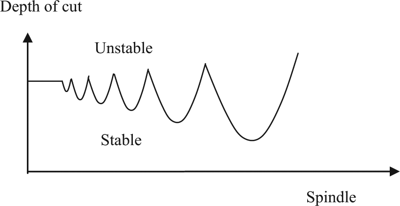
A typical stability lobe diagram.
Experimental measurements to obtain the stability lobe diagram of a machine tool are expensive and time-consuming. It is desirable to use mathematical models to predict it, although this is a complex and difficult computational problem. An example of stability prediction can be found in Huang et al., 46 Quo et al., 47 and Liu et al. 48 When the stability diagram is available, the stable region of the diagram can be applied as the constraint and optimize the machining parameters, to achieve optimal material removal rate 49 or surface variation. 50
Advances in CNC machining systems
This section reviews and introduces advances in CNC research from a systems and integration point of view. There are broadly three stages in the development of CNC machining systems, that is, CAM, automatic manufacturing and intelligent manufacturing. As this article focuses on part machining, the word “manufacturing” is replaced by “machining” in this article. Research and development in feature technology has played an important role in the CNC machining from both technological and system integration point of view. Therefore, some emphasis is given to the latest research in feature technology.
Computer-aided machining
The introduction of computers frees engineers from manual drafting of parts and process planning. A distinguishing feature of this stage is the assistance of computers. Before the advent of CAD technology, engineering drawings were the most commonly used technological documents for product design and manufacturing. The shapes and sizes of the machining features are represented by the orthographic views and the cross-sectional views. And the manufacturing requirements of machining features are represented by symbols and notes. In order to prepare a process plan, engineers need to interpret the geometry and manufacturing information from 2D drawings. Apparently, the quality of process planning depends upon the experience of the engineers. The machining process knowledge is hard to be stored and re-used.
In the mid-1960s, the first generation of CAD system was developed. Because it only provided 2D drafting function, strictly speaking early CAD systems should be called computer-aided drafting systems. 51 The digital files of 2D drawings have opened up the possibility of extracting machining features by computer programs. As an experiment, 2D drawings of the rotational parts were selected to verify the feasibility. 52 The application was extended to the prismatic parts gradually. 53 Then, isolated and non-intersecting features were extracted. 54 However, the intersecting features became the main obstacle. 55 Meanwhile, limited by the orthographic views, the features constructed by freeform surfaces were hard to extract. When the geometrical information was extracted, the dimensions of the machining features could be assigned automatically. 56 At present industrial practice, as the legacy data, 2D drawings of older products are still useful. Some researchers developed technologies for the reconstruction of 3D part models from 2D drawings. 57
When the machining features are extracted from 2D drawings, they can be used for process planning. Considering the similarity of the parts, Group Technology (GT) has been applied to code mechanical parts in variant CAPP system. Indexing rules were built to retrieve previous similar process plans according to the codes. Apart from GT technology, parametric process plan templates were widely used to store and represent the machining process of features. Process plans were generated by engineers who retrieve and modify the template library and solve related constraints according to the parameters of machining features.58,59 Then, the tool paths can be generated according to the machining feature parameters and the process information.
Because the interpretation of 2D drawings is bound by the experience of the engineers, 3D CAD systems were later developed. First, wireframe-based models were provided. The research work on feature extraction, process planning, and NC programming based on wireframe model was reported.60,61 However, the 3D wireframe models were ambiguous and were only suitable for quick display and verification of the geometry of simple feature models. 62
With the advances in CAD technology, solid models such as boundary representation (B-Rep) model and constructive solid geometry (CSG) models were proposed. A B-Rep model is capable of representing the lower-level geometric entities such as faces, edges, and vertices for attaching dimensions, tolerances, and other attributes. The CSG model is good at representing the higher level primitives such as removal volumes and easy performance of feature operations such as add, delete, and modify. Combining the advantages of the two models, hybrid CSG/B-Rep schemes were adopted in modern CAD/CAM systems. However, these models concentrate on the representation of geometry information. The machining process information were not properly stored and maintained in these models.
Automatic machining
In the later stages of system development, automation is the goal of research in CNC systems. The representative technologies include feature recognition, data exchange between CAD/CAPP/CAM, and feature-based NC programming.
Feature recognition
As an efficient and practical CAD/CAPP/CAM integration methodology, feature recognition methods can be categorized into graph-based method, volume decomposition method, hint-based method, artificial intelligence-based method, and hybrid method since the concept was first proposed. Some earlier researches in the development of feature recognition methods before 2005 have been reviewed by Han et al. 63 and Corney et al.; 64 more recent research on feature recognition is introduced below.
Woo et al. 65 integrated graph-based, cell-based maximal volume decomposition and negative feature decomposition using convex decomposition into a hybrid feature recognition method. These three methods construct a sequential workflow in order to reduce the solution space gradually, to achieve relatively optimized recognition results. Dimov et al. 66 developed a hybrid feature recognition method, which was mainly composed of feature learning and feature recognition. Knowledge acquisition techniques were applied for generating feature recognition rules and feature hints from training data. Then, these rules and hints were used to identify machining features from the B-Rep model. The machining features that could be recognized can be extended to other domains using different training data.
Arivazhagan et al. 67 depicted a machining volume identification method for finishing machining based on STEP AP 203-214. The machining volumes of the machining features defined in STEP AP 203-214 were calculated by their proposed algorithm. Obviously, the universality of the method was limited by the specific machining processes of rough machining. Marchetta and Forradellas 68 presented an easily customized manufacturing feature recognition method through stripping the feature definition and hints from the feature recognition algorithms. A knowledge-based model generator was built to describe the solid model of an input part by the declarative logic language. The features and their hints were also expressed by the declarative logic language. A general-purpose artificial intelligence planner called Graphplan+ was applied to recognize the manufacturing features from the knowledge-based representation of the part model.
Heo et al. 69 presented a methodology to recognize pocket features and to partition the machining regions of pockets. The attributes of pocket features were defined for high-speed machining planning. They used the slicing method that was similar to the method mentioned in Yu et al. 70 to generate multiple layers. Each layer has the same type of machining parameters to plan for high-speed machining. Chu et al. 71 presented a machining feature recognition method made up of two phases based on available resources of cutting tools. The machining surfaces that are machined by the same cutting tool form a machining feature. Rule-based reasoning is applied to optimize the recognized machining features which have the minimum number of setups.
Yu et al. 70 described a feature recognition method for an aircraft integral panel generalized pocket. The approach imitates the slice-machining process to use several planes whose orientation is the Z-axis direction to slice the part model into multiple layers. A feature profile is the intersection of the slicing plane and the part, which is used for tool path generation. This is inaccurate and time-consuming when a part consists of freeform surfaces. To improve this method, they proposed a principal face-based machining feature recognition approach. 72 The principal faces are extracted for defining the machining domains. The topological relationships between the principal face and its adjacent faces are used to identify the feature type of the machining domain. The number of types of machining features that could be recognized was extended.
Zeng et al. 73 put forward a simulated rolling method for the recognition of outer profile faces of aircraft structural parts. A vertical, infinite, and elastic revolving roller was imagined and moved toward the part under the gravitation of the part. When the roller touches the part with rotation, the pressure force and frictional force are generated. The resultant force drove the roller to roll along the outer profile of the part until it reached the position where the roller touches the part for the first time. Then, the outer profile faces of the part were extracted. As a type of machining feature of aircraft structural parts, the machining of the outer profile was closely related to the fix method of the part. The bosses distributed around the outer profile of the part used for clamping divided the outer profile into multiple sections which were machined separately. Therefore, the practicality of the method still needed to be improved.
Li et al. 74 proposed a feature recognition method based on a new concept called holistic attribute adjacency graph (HAAG) for aircraft structural parts. The HAAG extended the nodes and the attributes of the nodes in order to represent the geometrical and topological information of the part accurately. Benefiting from the HAAG, the intersecting features, convex features, and features consisting of freeform surface were able to be recognized. More research about feature recognition can be found in Babic et al., 75 Verma and Rajotia, 76 and Babic et al. 77
Data exchange between CAD/CAPP/CAM
Although the feature concept has been proposed for a long time, it is still difficult to give a uniform machining feature definition. International Standards Organization (ISO) tried to create a machining feature definition standard. The definitions or descriptions of different machining features are given in one of its application protocol (AP). ISO 10303 is an ISO standard for the computer-interpretable representation and exchange of product manufacturing information. It is known informally as STEP, which stands for Standard for the Exchange of Product data model. It follows the feature definitions of AP 224. Recently, STEP-NC has been proposed as a machine tool control language that extends the ISO 10303 STEP standards. Many researchers took advantage of STEP and STEP-NC to generate tool paths automatically.78–80
Feature-based NC programming
In order to improve the control and information integration capability of an NC machining system, Zhang et al. 81 suggested an NC feature unit (NCFU), which was a feature-based basic control unit. The NCFU processed geometric form and control parameters so that they were used as an information exchange hub between NC systems and other manufacturing execution systems. Meanwhile, NCFU used a geometrically defined closed and non-gouging machined area. In such a way, a machining volume object could be divided into a set of NCFUs to generate tool path in real time. Hou and Faddis 82 discussed the automation of tool path generation in an integrated CAD/CAPP/CAM system based on machining features. An integration layer between FBMach and Unigraphics was implemented to achieve CAD/CAPP/CAM integration based on machining features. Li et al. 83 developed a feature-based rapid programming system for aircraft structural parts. Machining feature was employed as carrier of process knowledge to drive tool path generation automatically.
Intelligent machining
The most recent research after automatic machining is intelligent machining. More knowledge with artificial intelligence technologies was applied to process planning, and to the prediction of on-line situations and make real-time decisions. The intermediate states of the machining features are considered in the process planning. And more complex situations such as machining of freeform surfaces were studied. The representative technologies include intelligent process planning, FSF machining, closed-loop machining, and definition of dynamic features.
CAPP
Benefiting from the development of feature technology, process planning has made much progress. Automatic or semi-automatic process planning was made possible through machining features as semantic carrier of machining process. Process planning can be divided into three levels: multi-domain process planning, macro process planning, and micro process planning. 84 Most previous research about process planning focused on macro process planning and micro process planning. In macro-level planning, the best sequence of multiple different processing steps and setups as well as the machines is selected. In micro-level planning, the details of each individual machining operation are optimized to determine the best process parameters. Some researchers optimized the machining process by integrating macro and micro levels.
Kafashi 85 presented a generative system and genetic algorithm (GA) to improve integrated setup planning and operation sequencing by adding tolerance relationships analysis in the problem constraints. Azab and ElMaraghy 86 gave a mathematical modeling method for reconfigurable process planning. Zhang and Ge 87 proposed an approach to determining optimal cutting tool sequences for machining multiple features in a single setup. Banerjee et al. 88 described an integrated process planning approach for optimal corner machining which combined tool path generation and machining parameter selection tasks. Rauch and Hascoet 89 proposed an approach to enhancing the implementation of plunge milling tool paths by computing the achievable material removal rate according to the tool path parameterization, the machine tool dynamics, and the machined feature properties.
Harik et al. 90 developed a CAPP system for aircraft manufacturing. A finer granularity machining feature called elementary manufacturing feature was proposed in their system. One elementary manufacturing feature consisting of a face or a face chain was associated with one machining operation. However, it was difficult to optimize the global process plan. Villeneuve et al. 91 presented a strategy and two models to perform a CAPP system. A feature model was developed to match machining processes adapted to aircraft knowledge. An activity model was developed to identify and clarify the tasks to be performed and the process data involved in making planning decisions. A more comprehensive review of process planning is given in Xu et al. 92
FSF machining
Research on FSF machining can be divided into process planning and tool path optimization. Process planning for FSF focused on the optimization of machining operation sequencing and the selected manufacturing resources, such as machine tools and cutters. For different machining stages, different optimization criteria should be applied. Because roughing strives for the highest material removal rate, normally three-axis machine tools combined with the flat-bottomed cutter are applied. Lee et al. 93 proposed a method to combine the cutters for machining different levels to improve the machining efficiency of roughing operations. Chen et al. 94 developed an integer programming (IP) method and a dynamic programming (DP) method to automate the traditional, experience-based cutter selection tasks and to reduce the total machining time in NC machining operations.
Semi-finishing aims to achieve even machining allowance for finishing stage. Finishing is intended to achieve the high machining quality with high machining efficiency. For three-axis machining, the cutter is selected according to the curvature of freeform surface. For multiple-axis machining, Lee and Chang 95 represented the effective cutting radius of a cutter by a function of the cutter size and the cutter orientation angles and selected the optimal cutter by geometric evaluation through the maximum effective cutting radius approach. Li and Zhang 96 developed a search algorithm that was able to find the accessible posture range for a given cutter in terms of the tilting and rotational angles. Then, the optimal cutter was selected to finish the entire surface without any interference.
Tool path optimization for FSFs can be classified into cutting width optimization, feedrate optimization, cutting force optimization, cutter orientation, and the combination according to different objectives. Cutting width optimization is also called strip width maximization machining which is intended to increase the effective cutting width as long as possible to achieve the shortest tool path and highest machining efficiency. Lee et al. 93 established the relationship between the strip width and the cutter orientation, cutting direction, and the geometrical parameters of the cutter to optimize the tool path. Cutting direction optimization indicated that the feedrate direction of every cutter location point was optimized under the limitation of the machine tool. Sencer et al. 97 expressed the variation in the feed along the five-axis tool path in a cubic B-spline form and adjusted the feed control points of the B-spline to maximize the feed along the tool path without violating the programmed feed and the drives’ physical limits.
The cutting force should also be optimized to improve the machining stability. Guzel and Lazoglu 98 presented a mathematical model for the prediction of cutting force system in ball-end milling of sculpture surfaces, which was used for selecting varying and appropriate feed values along the tool path in order to reduce the cycle time in sculpture surface machining. Through optimizing the cutter orientation, the interference and the smoothness of cutter orientation change were improved. Wang and Tang 99 presented an algorithm that could automatically generate a five-axis tool path that was not only interference-free but also guaranteed the angular-velocity compliance. Sun et al. 100 proposed a cutter orientation adjustment method to obtain an optimized tool path which made best use of the kinematic characteristics of angular feed for five-axis machining.
Closed-loop machining
Efforts have been made in on-line adjustment of cutting parameters and emergency actions and on-line tool path compensation. Katz et al. 101 presented a closed-loop machining cell for turbine blade finishing that integrated a robotic surface finishing device with an electro-optical, non-contact precision measuring system. Lasemi 102 developed a manufacturing method by integrating inspection and tool path generation to improve manufacturing quality while reducing manufacturing efforts. Some error compensation models were established based on the on-line inspection results, and the positive errors were compensated by adjusting the tool path.103,104 Ridwan et al. 105 proposed a system that consisted of an optimization module, a process control module, and a knowledge-based evaluation module, where STEP-NC was the underlying data model for optimization.
Dynamic features
In order to optimize the process plan of complex parts, the intermediate status of machining features needs to be modeled. 106 Ramesh et al. 107 established a feature template library for automotive components. Each type of feature template defined the removal volume. When designing a part using the feature template library, the intermediate status of machining features could be generated automatically. Park et al.108–110 extracted the boundary of the machined face and extruded the boundary to generate the removal volume of the machined surface. The intersection of the removal volume and the swept volume of cutter was the actual removal volume. The actual removal volumes were subtracted from the workpiece to generate the intermediate status of machining features. Li et al. 111 presented a dynamic feature representation method for high-value parts consisting of complex and intersecting features. The method first extracted features from the CAD model of a complex part. Then, the dynamic status of each feature was established between various operations to be carried out during the whole manufacturing process. Each manufacturing and verification operation could be planned and optimized using the real conditions of a feature, thus enhancing accuracy, traceability, and process control. The authors’ latest research in intelligent manufacturing based on a new dynamic feature concept is presented in section “A multi-perspective dynamic feature concept for intelligent machining” below.
A multi-perspective dynamic feature concept for intelligent machining
This section presents the latest research outcome of the authors’ research team in intelligent machining. The authors’ most important contribution to this research domain is a new concept of multi-perspective dynamic feature (MpDF) that has been implemented and applied to the aerospace industry. The authors recognized that in the current commercial and reported research prototype systems, features once defined normally remain unchanged in the whole manufacturing cycle, which are referred to as static features in this article. Machining planning and optimization based on static features often need manual corrections in response to various changes in dynamic production situations. Using the MpDF concept, changes in feature geometry and associated technical information can be represented within and complementary to existing feature-based CAD models so that adaptive machining planning and optimization can be carried out with accurate and actual component and resource information.
Definition of MpDFs
Changes in a feature during machining are defined in three perspectives as shown in Figure 2: (1) the geometry of a feature in the depth-of-cut direction changes during different machining operations such as roughing, semi-finishing, and finishing; (2) changes across the surface: a surface may be divided into different machining regions (effectively sub-features (SFs)) for the selection of appropriate manufacturing methods for each region such as different cutting tools, parameters, setups, or machine tools; and (3) changes in resources or manufacturing capabilities may require the re-planning of depth of cuts, division of machining regions, and manufacturing operations (machines, tools, setups, and parameters). The MpDF concept could be used to support machining decision-making of complex parts with complex structures (and with freeform surfaces) and can be formulated as

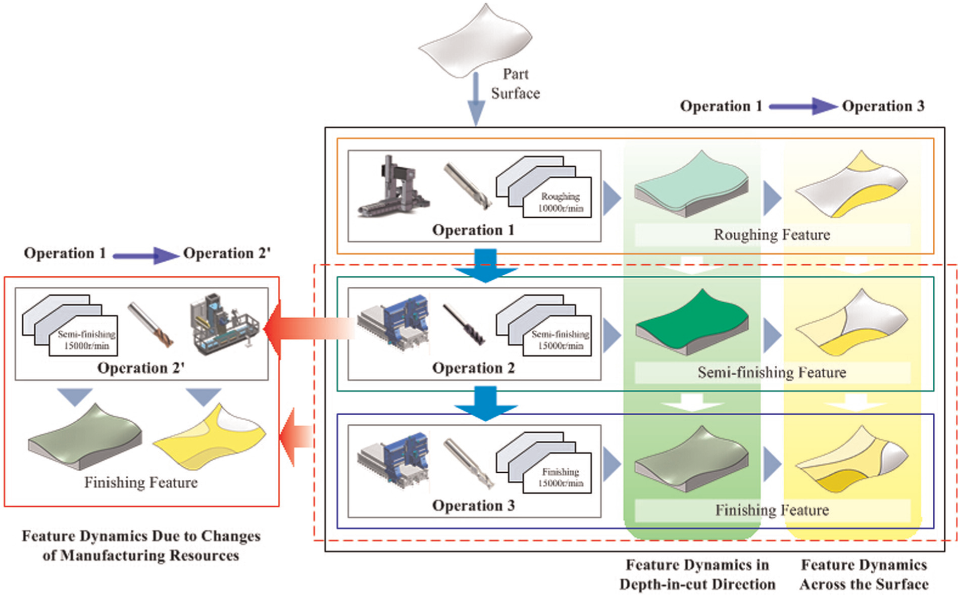
Changes in a feature defined in MpDF.
where IF refers to an interim feature with its SF on part (P). Γ refers to the feature division algorithm. OOT and MRT are the optimization objectives and manufacturing resources, respectively. With the MpDF concept, a feature information model in CAD systems can be defined dynamically in the whole manufacturing cycle, thus supporting on-line adaptive machining planning.
Feature dynamics in the depth-of-cut direction
Feature dynamics in the depth-of-cut direction defines IFs to represent the information about real feature status and changes in its geometry between different machining operations. 111 Undesired machining effects like overcut and undercut in IFs are detected to evaluate existing process plans. Machining effects transition (MET) is then carried out by considering certain validity constraints to optimize the process plan in a much more global way. Moreover, IFs provide a possibility to define features for different machining stages like roughing, semi-finishing, and finishing. By considering feature dynamics in this perspective, each manufacturing and verification operation can be planned and optimized using the real conditions of a feature, thus enhancing accuracy, traceability, and process control.
Feature dynamics across the feature surface
Feature dynamics across a surface indicates that the surface may have to be further divided into several machining regions (effectively SFs) for the selection of appropriate manufacturing methods for individual machining regions including cutters, parameters, setups, and machine tools. Surface subdivision aims for better machining results, for example, flat-end cutters may be chosen to machine convex and relatively flat regions, while ball-end cutters may be used to machine concave regions with small curvature to avoid gouging/overcutting. The authors developed a surface subdivision method based on tensor field and a boundary point classification principle. Existing freeform surface machining optimization methods are mainly based on scalar or vector which only represents the machining information in one feed direction at a time as shown in Figure 3. For example, only the directions with maximal cutting width are defined in machining potential field. 112 Because of the complex nature of geometry and machining operation, optimized results cannot be achieved everywhere in the freeform surface. Thus, most of these methods are greedy, and only local optimized machining results can be achieved.
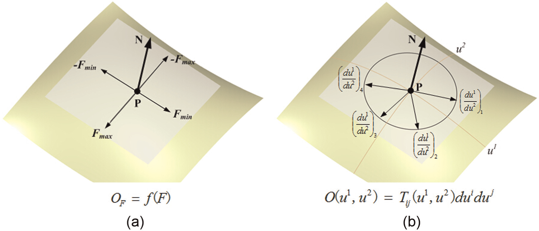
Representations of optimization objectives: (a) scalar or vector based and (b) tensor based.
To overcome the shortcoming, optimization objectives are represented based on a second-order tensor, that is

where
The adjacent SFs have different cutting methods to machine the point. However, both methods are optimized at this point. In this condition, emax equals to emin. Thus, O(
The adjacent SFs have the same cutting method to machine this point. In this condition, the maximum or minimum eigenvector at the point is coincident with the tangent vector of the tensor line crossing the point. This kind of boundary points is named as normal boundary point (NBP).
A two-step procedure is developed to construct SF boundaries as shown in Figure 4. DBPs in the surface are generated as the starts to construct SF boundaries. First, a tensor is selected based on the current
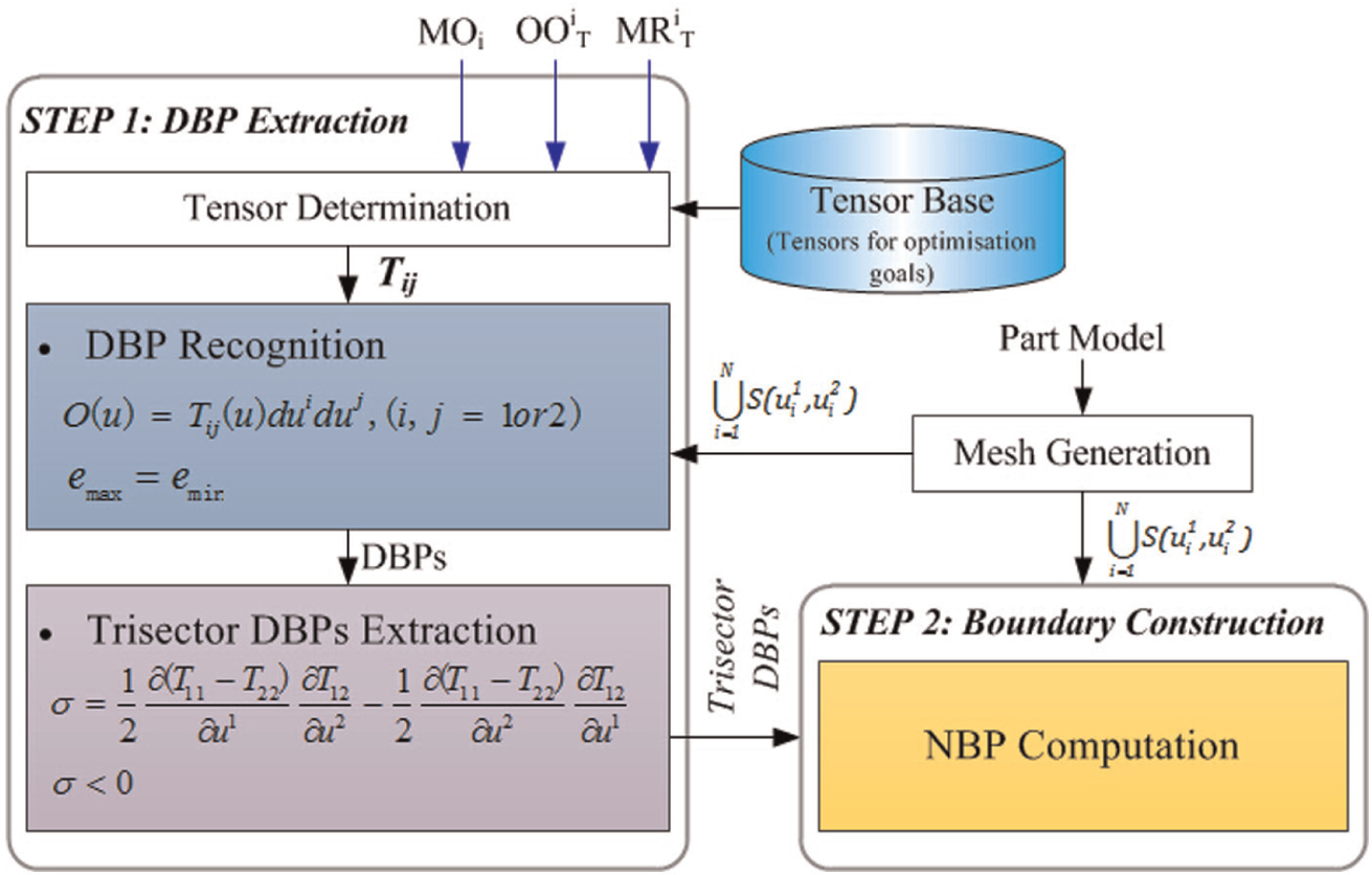
Procedure for sub-feature boundaries’ construction.
Currently, the authors have obtained the tensor metrics for cutting width and machining time considering machine kinematics. Figure 5 shows two examples for cutting width maximization in surface finishing. The test surface is first divided into several sub-regions using the proposed tensor-based method. Then, in each sub-surface, tool paths will be generated by offsetting the initial tool path curve which follows the optimal feed direction (with maximal machining strip width) at every discrete point. Compared with the iso-parametric tool paths, both the tool path length and machining time are much reduced by applying MpDF concept.
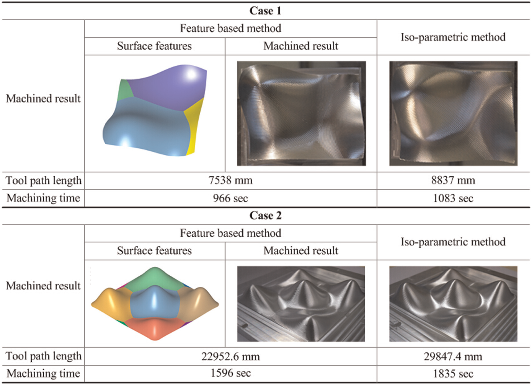
Two cases for cutting width maximization in surface finishing.
Feature dynamics due to changes in manufacturing resources
Feature dynamics due to changes in manufacturing resources is important for intelligent machining in today’s manufacturing industry which faces more and more uncertainties. Machine tools, cutters, fixtures, as well as cutting parameters may have to be changed frequently due to factors like product changeover, urgent job insertion, and broken tools. Normally, machining operations and optimization objectives, once planned, remain unchanged during the whole manufacturing cycle. However, the selected manufacturing resources in initial planning stage are often changed by engineers in real production. If the changes are due to re-scheduling of resources or machine breakdown, the planned machining operations as well as optimization objectives may need to be re-planned which can lead to changes in both the IFs and the way SFs are generated for each IF as shown in Figure 6. As a result, the MpDF information model would be updated, and thus, adaptive machining planning is supported with the timely accurate information in the MpDF model.
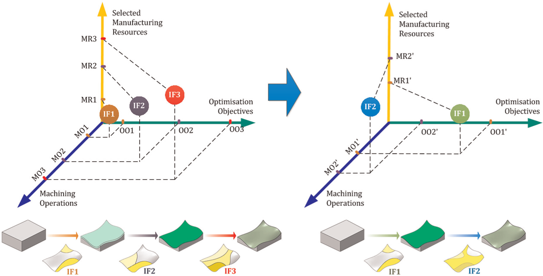
Feature changes due to changes in machining resources.
Summary and future outlook
Section “Advances in CNC machining technologies” of this article provides an overview of the main theories, methods, and technologies addressing a range of key engineering aspects of recent research in CNC machining, focusing on three themes, that is, simulation, optimization, and automation. Various physical aspects (including geometry and dynamics) are simulated in order to predict the results before actual machining takes place; using advanced mathematical models, algorithms, and computing technologies to tackle complex problems and produce more reliable predictions, and improve process data (including tool paths) to achieve better machining outcome.
There are various process (machining) parameters, and selecting the best set of parameters is an almost impossible task. Taking advantage of simulation, optimization, and automation, “near” optimal machining processes may be derived, instead of merely usable processes. The optimization problems are usually solved numerically. These efforts substitute human decision-making with mathematical reasoning. However, the technology is still at the early stage of intelligent machining, and there is still significant work to be done.
Section “Advances in CNC machining systems” of this article provides an introduction to the enabling information and computing technologies (ICTs) that bring the methods and technologies in CNC together into integrated systems with various modeling and decision-making modules to support intelligent machining. As the information and knowledge carrier, feature is the efficacious way to achieve intelligent manufacturing. From the regular-shaped feature to FSF, the feature technology has been used in manufacturing of complex parts, such as aircraft structural parts. Meanwhile, the dynamic feature definition provides a very efficient and effective mean of optimizing the complex machining process.
To summarize this review, the authors believe that the research in CNC machining has entered a new phase: intelligent machining. It will be a flourishing research area and exciting new results and progress will be seen in the forthcoming years. Section “A multi-perspective dynamic feature concept for intelligent machining” of this article presented a comprehensive MpDF concept proposed by the authors, which has the potential to model the actual status of features during different operations in real production situations, thus supporting more accurate prediction, planning, and optimization. As an initial contribution to the intelligent machining research, the authors anticipate more international research into this important research area.
Footnotes
Declaration of conflicting interests
The authors declare that there is no conflict of interest.
Funding
This work was funded by the National Natural Science Foundation Project of China (No. 51375239), the National Science and Technology Major Project of China (No. 2012ZX04010041), and the Jiangsu Province Outstanding Youth Fund (No. BK20140036). International collaboration was supported and included in these projects.