
Abstract
Feature-based manufacturing methodologies offer opportunity for numerical control machining effectively and efficiently. However, the loss of drive geometries caused by the complex shape and machining process of aircraft structural parts undercuts the advantage of feature-based manufacturing tools. To better address the gap between the process planning and tool path generation for aircraft structural part, a drive geometry construction approach based on the topological relationships and machining process of machining features for process planning are proposed. The created drive geometries correspond with the optimized machining process. The drive geometries that define the machining areas of machining features are categorized into guide lines and guide faces in accord with the machining mode, such as 2.5- to 3-axis machining and multi-axis machining. In contrast to the traditional performing of intersection operations with a series of slice planes and the part model manually, the drive geometries are constructed by extracting the existing topological entities and creating some auxiliary topological entities automatically. The drive geometry preparing time and the consumption of computer memory are reduced significantly. The proposed approach has been tested and used in a pilot feature-based programming system that is developed for some aircraft manufacturers in China.
Keywords
Introduction
In order to keep and increase the market share, the keen competitions force the enterprises to develop and employ new technologies to decrease time to market and to reduce the cost of products. In recent years, the monolithic parts are used widely for the improvement of aircraft performance that shows higher assembly precision and reliability. The use of integral structural parts brings an immediate benefit of weight saving in comparison with riveted structures because of the elimination of overlaps at joints and stringer attachments. In addition, their use also significantly reduces the cost of materials and machining effort in structure manufacture. 1 However, the problem of low efficiency and quality of numerical control (NC) programming undercuts the advantage of the integral structural parts. According to statistics, the ratio of machining time to programming time for aircraft structural parts is typically 1 to 10. 2
Feature-based manufacturing (FBM) methodologies offer opportunity for NC programming effectively and efficiently. A great deal of researches has been published on feature-based integrated computer-aided design/computer-aided process planning/computer-aided manufacturing (CAD/CAPP/CAM) methods. Moreover, some CAD/CAM software vendors have developed and released their feature-based machining modules, such as feature-based machining module of Siemens’ product lifecycle management (PLM) Software NX®, FeatureCAM® of Delcam and CAMWorks® of Geometric. However, due to the complexity and difficulty of the technologies, the existing methods focus on providing the connection between process planning and tool path generation for the general mechanical parts with simple structures. The connections between process planning and tool path generation are so powerless that the process plan information cannot be applied for tool path generation directly, especially for complex parts such as aircraft structural parts.
As the bridge between process planning and tool path generation, drive geometries are the most important information for tool path generation. However, the complex shape of aircraft structural parts associated with complicated machining process leads to the loss of the drive geometries:
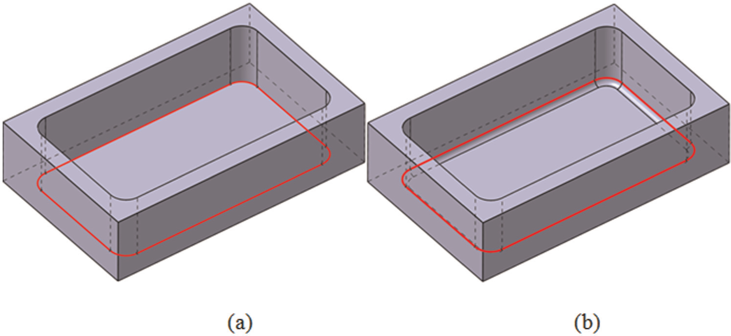
The intersecting features destroy not only the feature hints for feature recognition but also drive geometries for tool path generation. Take the common stepped pocket feature in aircraft structural parts shown in Figure 1 as an example; the milling of the pocket side is divided into two machining operations. The first operation cuts the pocket side of the higher layer, and the second operation cuts the pocket side of the lower layer. The drive geometries of the higher layer are no longer the outer domain of the bottom. If the outer domains of the pocket bottom are still defined as the drive geometries, the milling operations will leave uncut materials on the side. Actually, the drive geometries of the higher layer should be reconstructed to cover the whole side above the bottom of the higher layer.
The complicated machining process that consists of multiple machining operations determines that the drive geometries of each operation are interrelated. The drive geometries of the former machining operation decide the drive geometries of the latter operation. For instance, the drive geometries of corner milling are limited by the drive geometries of side milling of the pocket as shown in Figure 2. The drive geometries of side milling defined the start and the end of the drive geometries of corner milling. Therefore, the drive geometries must be constructed dynamically in accord with the machining process plan.
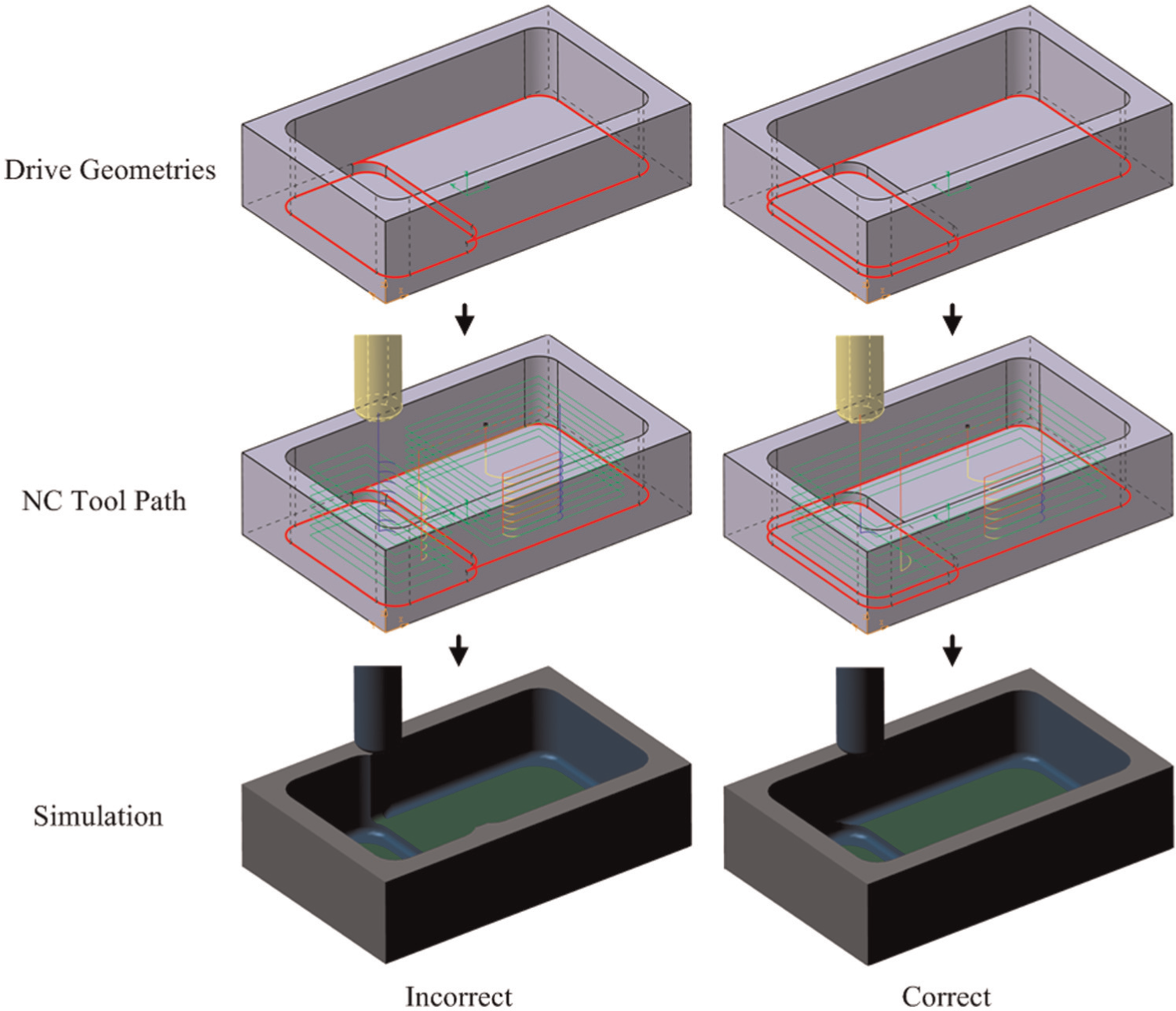
Machining of a stepped pocket.
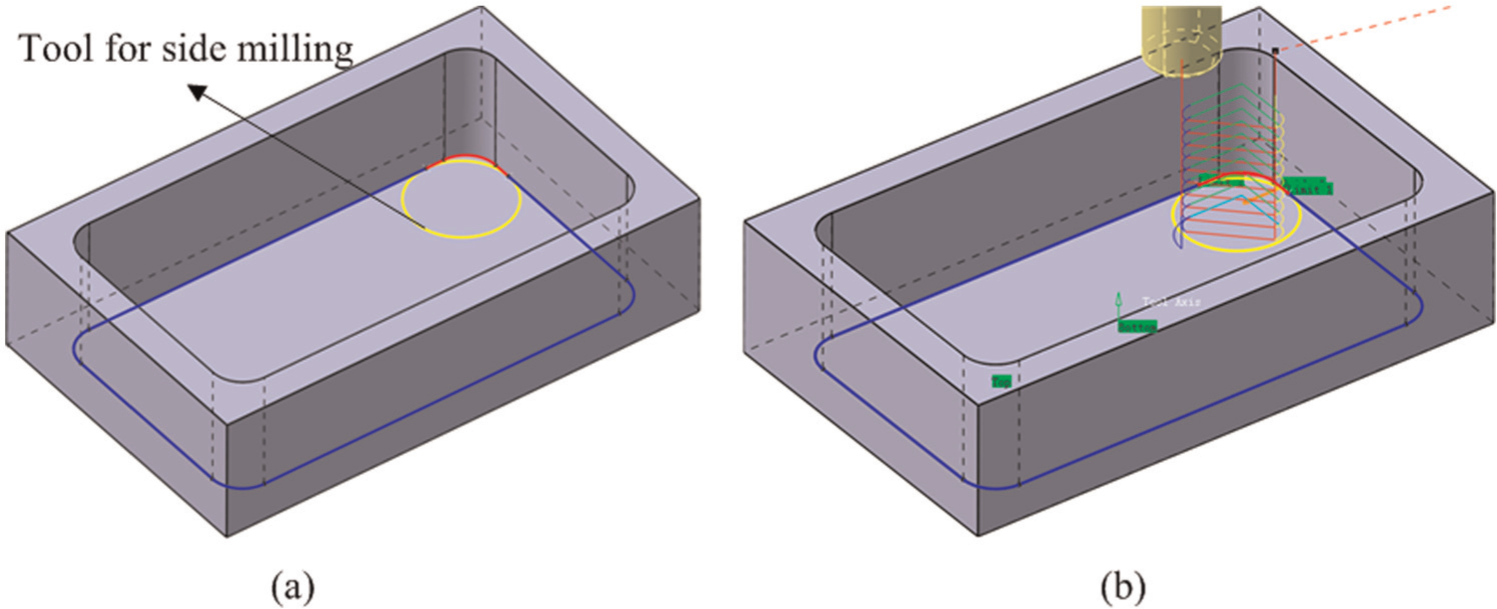
Machining of a corner: (a) drive geometries for corner milling and (b) NC tool path for corner milling.
On the basis of the descriptions above, a drive geometry construction approach based on the topological relationships and machining process of machining features is proposed in this research. The constituted elements of the drive geometries can be found through analyzing the topological relationships between topological entities of machining features. Then, the constituted elements are extracted to construct the drive geometries in accord with the machining process.
The sections of this article are organized as follows: section “Literature review” reviews the related researches. The definition and the classification of drive geometry are described in section “Drive geometries.” Section “Drive geometry construction algorithms” presents the construction algorithms of the drive geometries for different machining features. A case study in section “Case study” shows the performance of the proposed method. Conclusions are in section “Conclusion.”
Literature review
As playing a critical role in feature-based machining, drive geometry is always an active research field in process planning and tool path generation.
Process planning
A good process plan can lead to an efficient and high-quality manufacturing result. Most researches on process planning focus on setup planning, selection of machine tools and cutters, process parameter optimization, operation selection and sequencing, nonlinear process planning and so on. 3 There are a few research studies on drive geometry. Heo et al. 4 presented a methodology to partition the machining region of the pockets. They used a series of slice planes to partition the pocket feature into multiple layers. The intersections between the slice planes and the side faces of the pocket feature are the drive geometries for pocket milling. The partition rules are the emphasis in this research. The drive geometry construction is relatively simple. Harik et al. 5 proposed a feature-based process planning method for aircraft component manufacturing. Their method is mainly divided into three steps: geometrical enrichment, elementary manufacturing feature (EMF) extraction and manufacturing feature identification. In the second step, machining modes, machining tools and machining direction were associated with every EMF that is composed of one machining face. In the third step, the EMFs that have the same information issued in second step are combined into the manufacturing features that are then labeled with different colors. Because only the machining faces are extracted, the drive geometries consisted of faces have been constructed. Jin et al. 6 developed an adaptive process planning method for rapid prototype and manufacturing. This research uses the similar slice method described in Heo et al. 4 to generate the multiple sliced layers. The contours of sliced layers of biomedical CAD models are the drive geometries for tool path generations.
According to the analysis above, using a series of slice planes to intersect the feature model to generate the drive geometries is the sole method. On the one hand, the intersection operations cause the increase of computer memory consumption and the part model size. On the other hand, the intersection operations do not always work well. The constituent faces of the drive geometries are extracted and regrouped based on the machining process. However, the relations between the constituent faces have not been established.
Tool path generation
As the knowledge carrier of machining process, machining features are used to achieve machining knowledge reuse and the automation of tool path generation.7,8 Most tool path generation researches focus on tool path strategy, 9 machining time reduction, 10 tool path optimization for achieving better machining quality11,12 and so on. 13 In contrast with process planning, there are more researches on drive geometries.
Zhang et al. 14 developed a next-generation NC machining system based on NC feature unit (NCFU) and real-time tool path generation. As a subclass of the traditional high-level feature class, the NCFU is composed of geometric form and control parameters. The machining area represented by each NCFU is nongouging, which facilitates the tool path generation in real time. The geometry information in each NCFU should be drive geometries. However, the details of the drive geometry construction were not described in this article. Miao et al. 15 developed a feature-based integrated CAD/CAPP/CAM system which could automate the process of machining process planning and tool path generation for 3-axis machining. The drive geometries for machining operations are encapsulated into the machining operation objects. Similarly, they did not describe the drive geometry construction of machining operations. Hou and Faddis 16 developed an integration layer between Unigraphics software and FBMach which has the function of packaging the geometrical information and process parameters of machining features into some CAM objects defined in Unigraphics software. However, the details of how to generate the geometrical information used in CAM objects are not described. Contour-parallel offset (CPO) machining is the most popular machining strategy for pocketing. The islands resided in the pockets lead to more tool retractions and lower material removing efficiency. Hence, Park and Chung 17 provided an offset tool-path linking method for pocket machining to improve the productivity of the tool path. After offsetting the original contour, the linking method partitioned the machining area into several isolated sub-machining areas which have their own new contours, that is, the drive geometries. For the same purpose, Owodunni et al. 18 proposed a Voronoi-diagram-based linking of contour-parallel tool path generation method for two-and-a-half-dimensional closed-pocket machining. Tapie et al. 19 established a topological model for machining of parts with complex shape which appeared widely in the aeronautics, automotive and other applications. The topological relationship between different machining features is extracted and represented by topological graph in order to reduce the preparation time for process planning.
It can be concluded from the described review that the researches have reached a consensus that encapsulating the drive geometry information and machining process information into the machining operations is a practical method to build the bridge between process planning and tool path generation. However, these researches focus on general mechanical parts with simple shape and machining process. The drive geometry constructions emerge as a result of the application range extension of feature-based machining, such as aircraft structural parts with complex shape and machining process.
Drive geometries
Drive geometry is a technical term that is referenced for tool path generation in NC CAM software. The drive geometries of a machining feature determine the machining area in the space across which the cutter cannot move. According to the machining mode, the drive geometries are categorized into guide lines and guide faces. The drive geometries of machining features depend on the machining processes of machining features. Therefore, the details of machining process for each machining feature are obtained from the process planning described in Li et al. 20
Guide lines
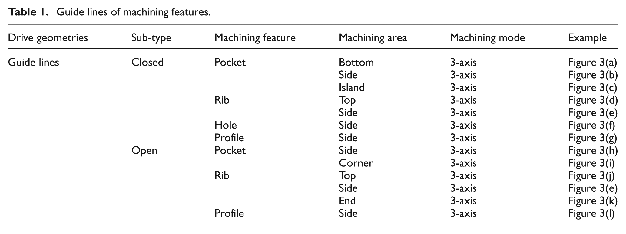
In 2.5- to 3-axis machining, the spindle is constantly in the z-direction. As a result, the boundary lines are employed to define the machining area and act as the drive geometries. The drive geometries are applied for tool path generation for closed tool path strategies and open tool path strategies. The details of different machining features for 3-axis machining are shown in Table 1 and Figure 3. It should be pointed out that the drive geometries of rib side milling are different on account of the thickness of the rib. When the rib is thick with good rigidity, the drive geometries are the closed loop. Nevertheless, if the rib is thin with poor rigidity, some special tool path strategies are adopted, such as the “jump to jump” tool path described in Bravo et al. 21 Then, the closed loop should be separated into several single guide lines.
Guide lines of machining features.
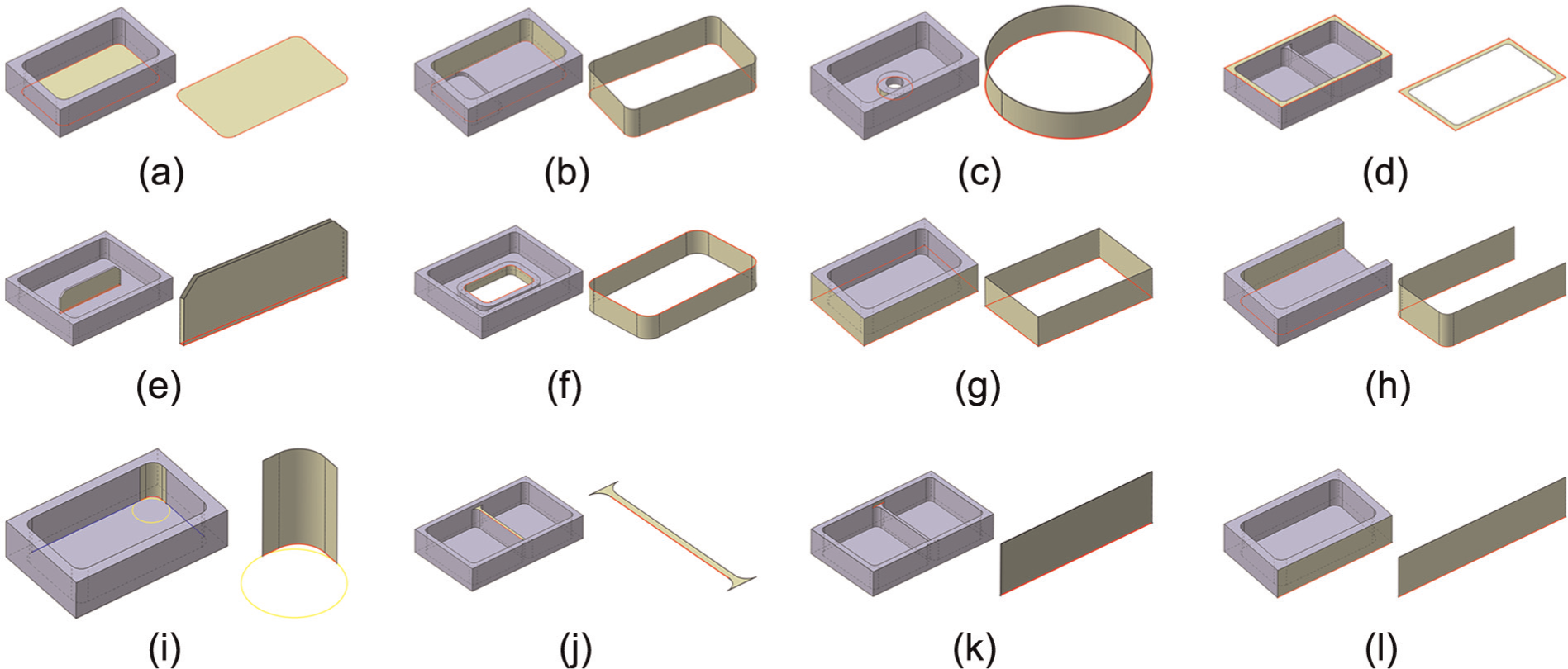
The drive geometries of machining features for 3-axis machining.
Guide faces
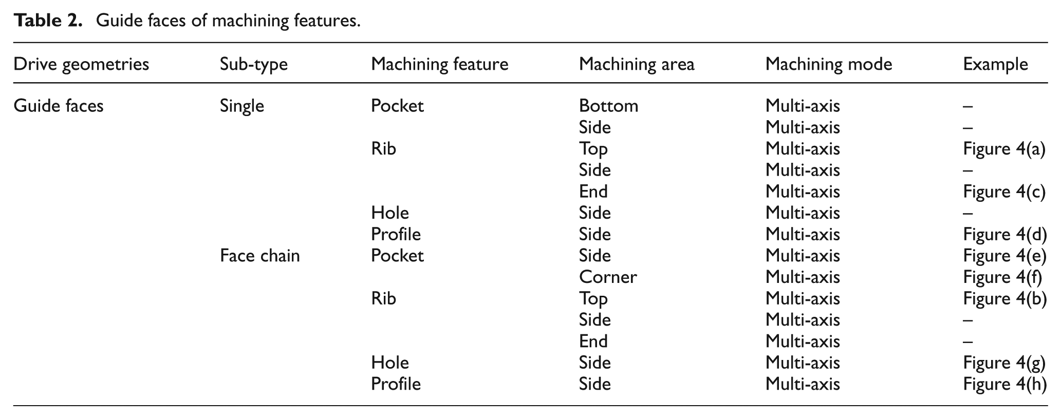
For multi-axis machine, the spindle and the worktable are swing. Only the boundary lines are not enough to define the machining area. Therefore, the guide faces are introduced to do the duty for drive geometries. The details of different machining features for multi-axis machining are shown in Table 2 and Figure 4. Some situations that do not appear in aircraft structural part NC machining are not given in Table 2 and Figure 4.
Guide faces of machining features.
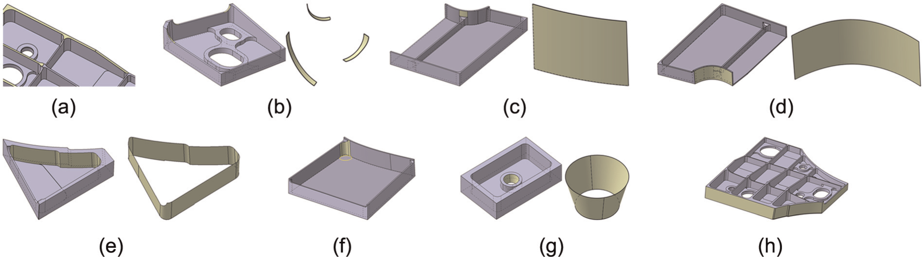
The drive geometries of machining features for multi-axis machining.
Drive geometry construction algorithms
Generally, the bottom of a pocket feature is machined by 3-axis end milling. The guide lines are outer domain of the bottom face. But the varied side faces of a pocket which mix the open-angled faces with the closed-angled faces make it difficult to get the guide lines which ensure that the cutter will not touch the closed-angled faces. The guide line creation algorithm for bottom milling of a pocket feature is divided into the following six steps:
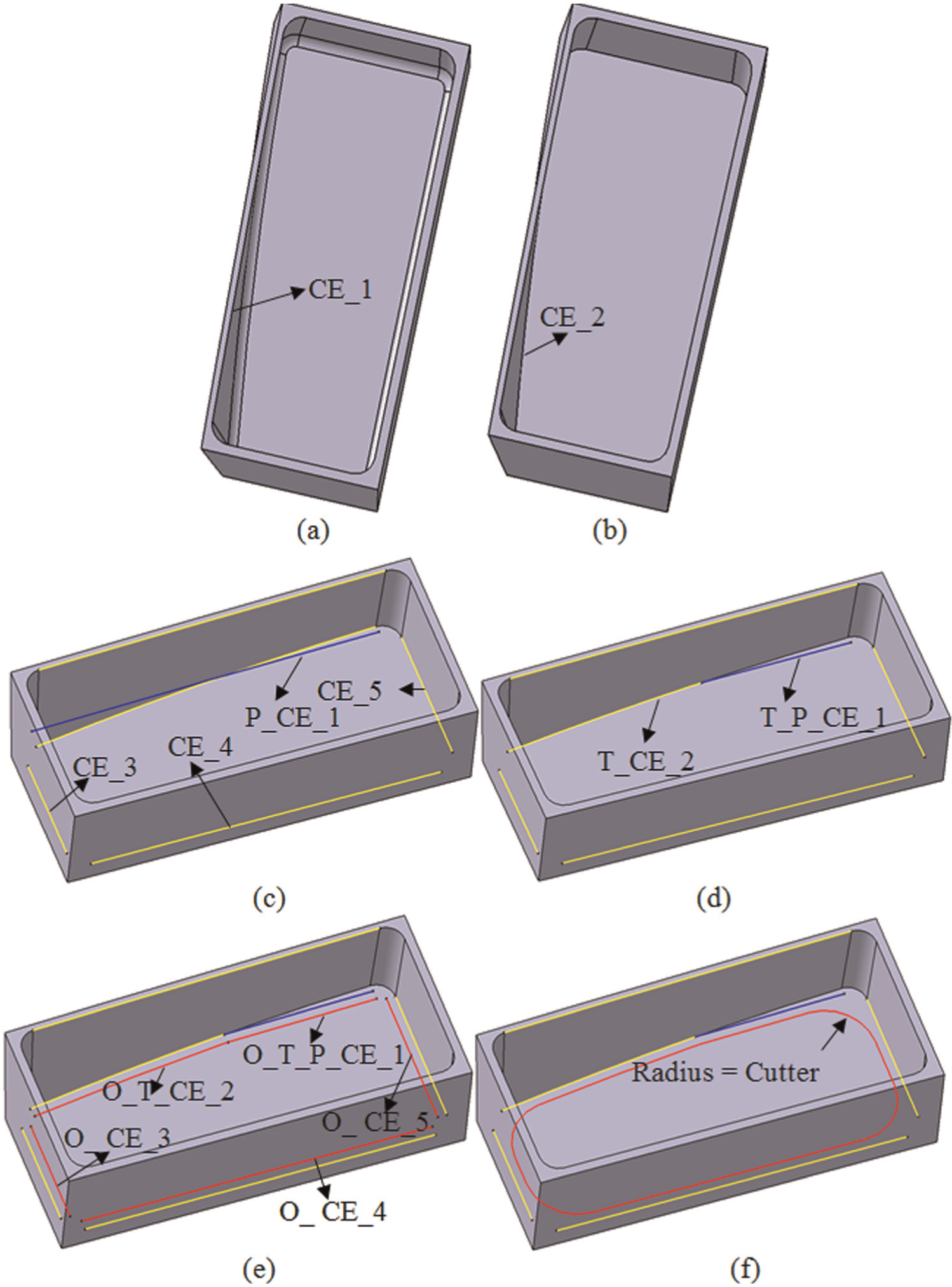
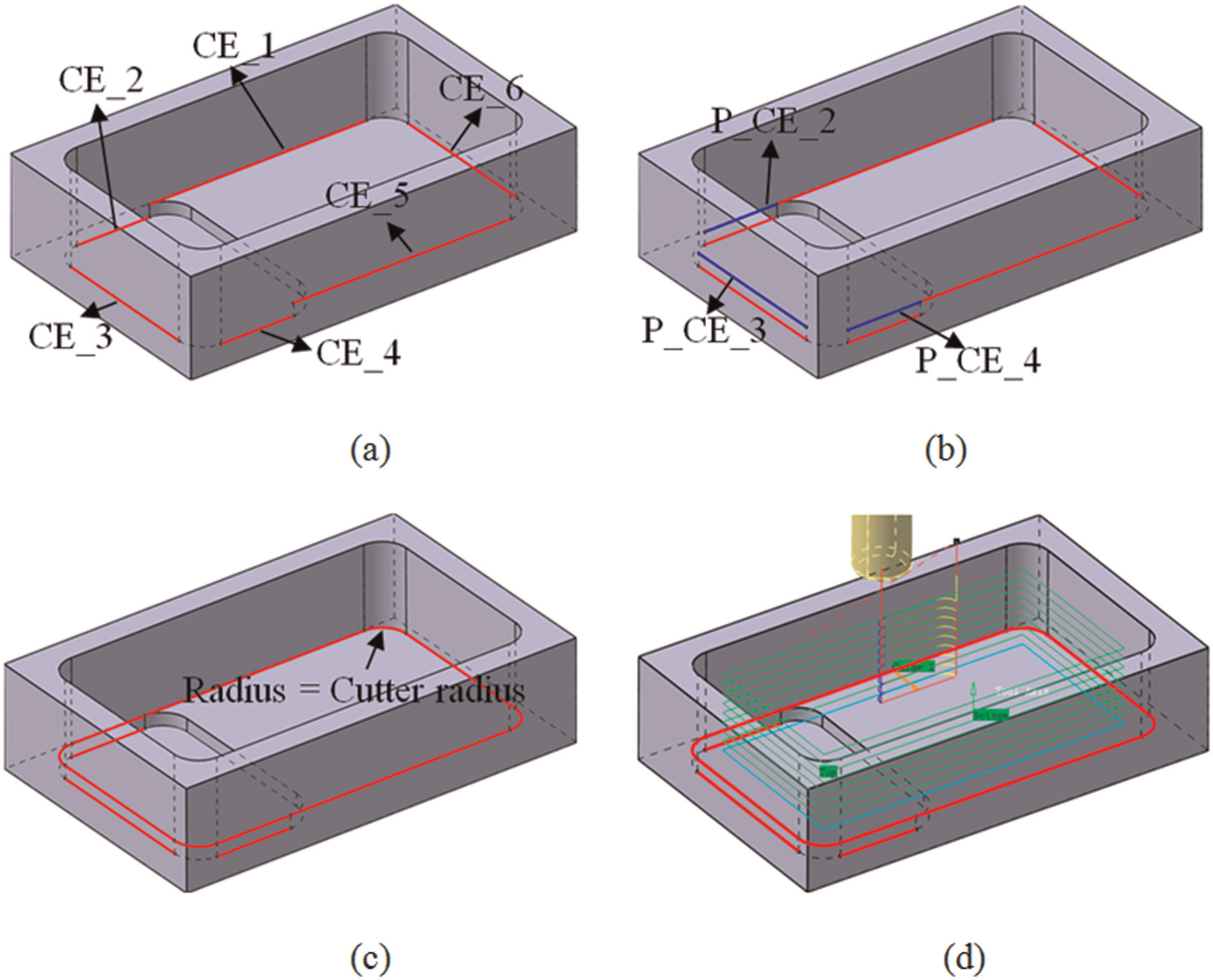
Step 1. Extract the constituent edges. The extract rules vary owing to different topological relations between the adjacent faces. If the relation between the side face and the bottom face is closed angled, the edges shared by the side face and its adjacent face, which are not in the pocket feature face set, are the constituent edges, for example, CE_1 shown in Figure 5(b). If a fillet is created between the side face and the bottom face as shown in Figure 6(a), the constituent edge is hid as a hint. Once the fillet is suppressed, the constituent edge is appeared as shown in Figure 6(b). One side face of a pocket feature shown in Figure 6(a) is open angled mixed with closed angled. In this case, one constituent edge is the edge shared by the side face and its adjacent face, for example, CE_1 shown in Figure 6(a). The other one emerges from the suppression of the rounding faces, for example, CE_2 shown in Figure 6(b). When the relation between the side face and the bottom face is perpendicular, the constituent edge is the edge shared between the blend face and the side face, for example, CE_2 and CE_3 shown in Figure 5(b), or is the edge shared by the side face and the bottom face after the fillets are suppressed, for example, CE_3, CE_4 and CE_5 shown in Figure 6(d). When the bottom is open, this means that some edges of the bottom face are not shared with any side faces. If so, these unshared edges are the constituent edges for the milling of the bottom, for example, CE_4 shown in Figure 5(b).
Step 2. Project the constituent edges which do not lie on the bottom face to the bottom face. The projections are marked in blue with a prefix “P” in Figures 5 and 6.
Step 3. Trim the constituent edges and the projections created in step 2. The results are expressed with a prefix “T” in Figure 6.
Step 4. Endow the trimmed results and the other constituent edges with soft or hard characteristic. The constituent edge like CE_4 shown in Figure 5(b) is a soft edge; the cutter will move on it as shown in Figure 5(e). When the edge is a hard edge, the cutter will move on it as shown in Figure 5(d).
Step 5. Offset the edges with hard characteristic for allowing side machining. The offsets are marked in red with a prefix “O” in Figures 5 and 6.
Step 6. Connect all offsets into a closed loop with circular arcs whose radii are equal to the radius of cutter which is used to milling the bottom as shown in Figures 5(c) and 6(f). This closed loop as drive geometries is the final guide lines for the bottom milling.
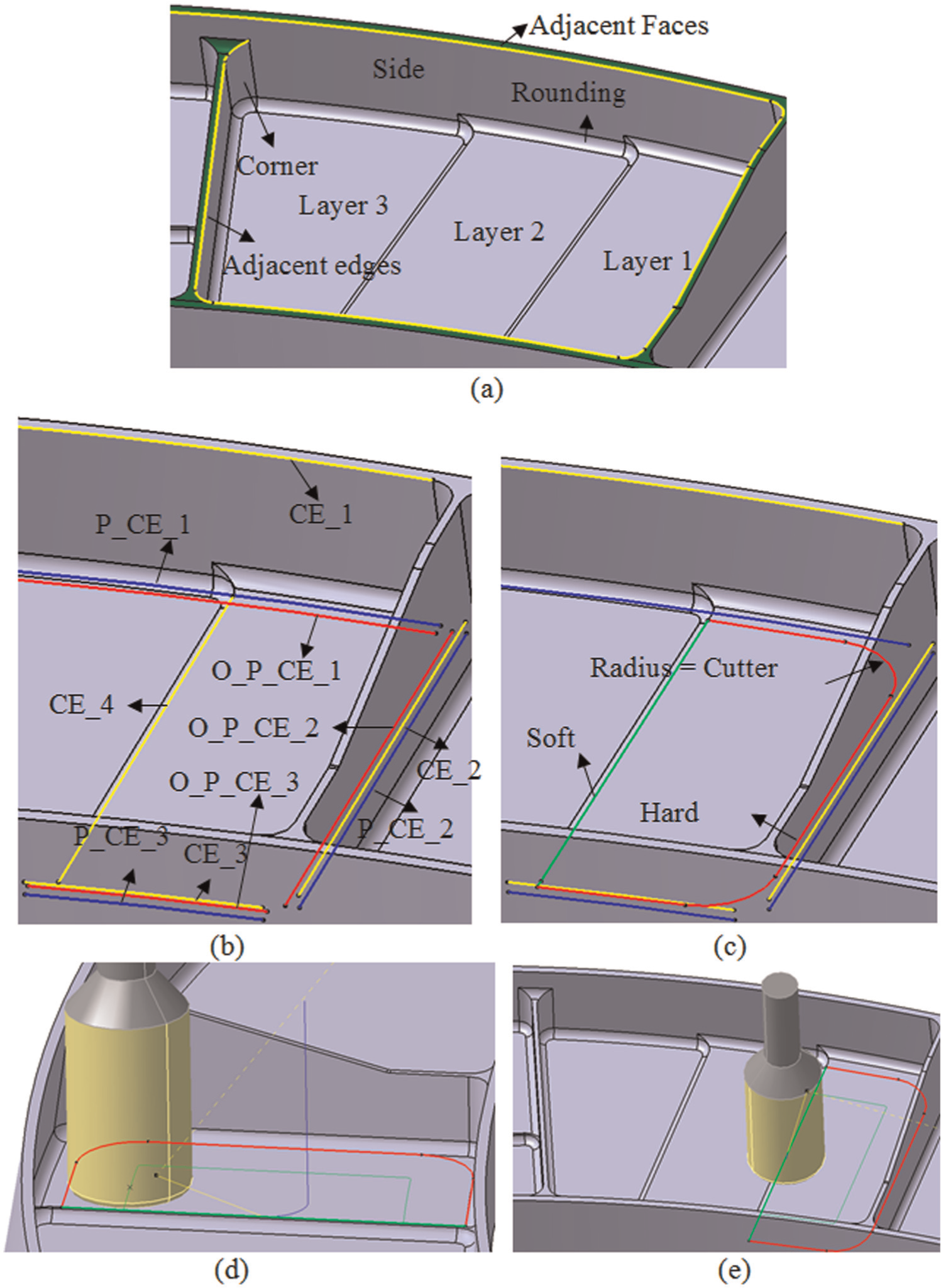
Bottom milling drive geometry construction of the pocket with closed-angled sides.
Bottom milling drive geometry construction of the pocket with mixed angle sides.
When the side of a pocket feature is machined by 3-axis end milling, the guide lines of the side milling are the common edges of the bottom face and the side faces after suppressing the rounding faces as shown in Figure 7(a) or the common edges of the bottom face and the rounding faces as shown in Figure 7(b). In order to avoid material remains located at the side junction of the higher layer and the lower layer, the side milling drive geometries of the higher layer should cover the side of the lower layer as shown in Figure 1.
Three-axis side milling drive geometry construction of a simple pocket feature.
The algorithm of creating drive geometries for a stepped pocket side machining in the 3-axis machining mode consists of the following three steps:
Step 1. Extract the constituent edges. Because the relations between the bottom faces and the side faces are perpendicular, the edges shared by the blend faces and side faces are the constituent edges as shown in Figure 7(b). When the fillets are suppressed, the constituent edges of the higher layer side milling are the edges shared between the side faces and the bottom faces of the current layer and the lower layers, like CE_1 to CE_6 shown in Figure 8(a).
Step 2. Project the constituent edges which lie on the bottom faces of the lower layers to the bottom face of the current layer. The projections are marked in blue with a prefix “P” in Figure 8(b).
Step 3. Connect the projections created by step 2 and the other constituent edges into a closed loop with circular arcs whose radii are equal to the radius of cutter which is used for side milling. This loop is the guide line as shown in Figure 8(c). The tool path is shown in Figure 8(d).
Three-axis side milling drive geometry construction of a stepped pocket feature.
The algorithm of establishing the drive geometries for corner milling is divided into the following two steps:
Step 1. Extract the constituent edges. The constituent edges are the common edges between the bottom faces and the side faces and the corner faces when the fillets are suppressed as shown in Figure 2(a), otherwise are the common edges between the rounding faces and the side faces and the corner faces as shown in Figure 9.
Step 2. Trim the constituent edges with circular arcs whose radii are equal to the radius of cutter which is used for side milling at the corners of the pocket feature. The trim results in red are the guide lines for corner milling as shown in Figures 2(a) and 9.
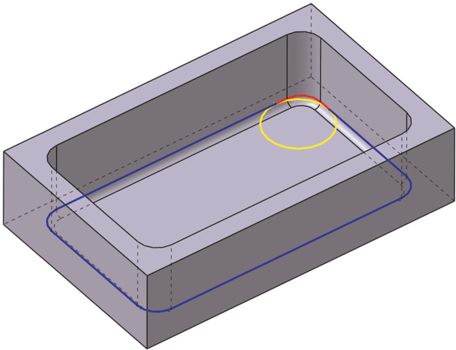
Creation of drive geometries of a corner.
The corner milling tool path is shown in Figure 2(b). The islands nested in pockets decrease the range of cutter movement in machining bottom of pocket, and their sides are also required to machining. The holes in aircraft structural parts are mainly located at the bottom or side of pocket. No matter what machining mode is applied for machining hole, the drive geometries are the same. The algorithms of creating drive geometries for islands and holes are similar. The constituent edges of their drive geometries are the edges of inner loops bounding the side or the bottom of pocket, as well as are edges shared by the side faces and blending faces or by the blending faces and bottom faces. Dissimilarly, the relation between island sides and bottom is concave. The relation between hole sides and bottom is convex.
The chains of faces as drive geometries are aimed at machining area surrounded by inclined planes and free-form surfaces. It is difficult to use boundary lines to express the machining area accurately for free-form surface machining. Therefore, the chains of faces are applied to generate tool path. The faces in the chain of faces are the constituent faces of the machining feature. The relations between the constituent faces are the key to tool path generation.
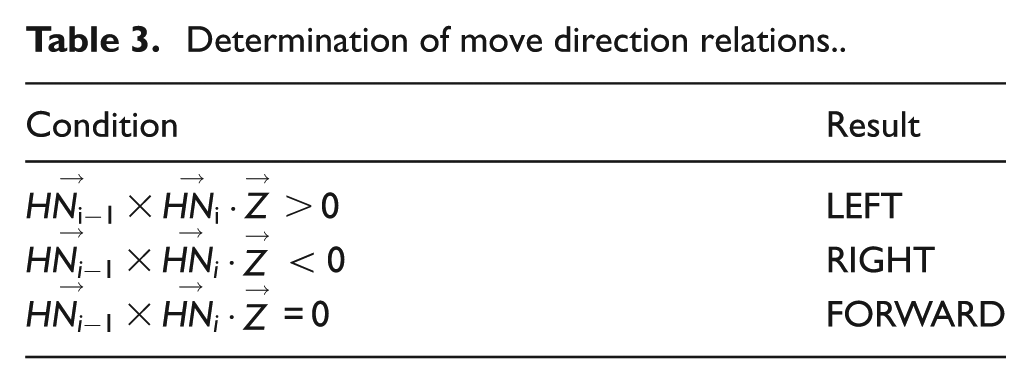
These relations are divided into move direction relations and link relations. The move direction relations determine the tool move direction along the current machining face and are subdivided into LEFT, RIGHT and FORWARD as shown in Figure 10.
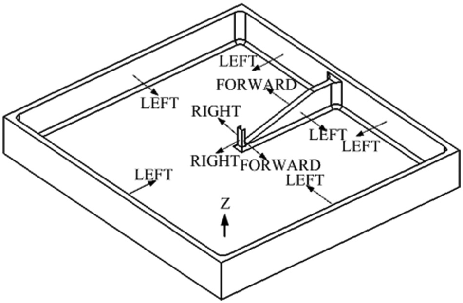
Move direction relations between drive geometries of a pocket feature.
Taking a face from the drive geometries as an example, the center of the face is O, and the normal direction at O is
Determination of move direction relations.
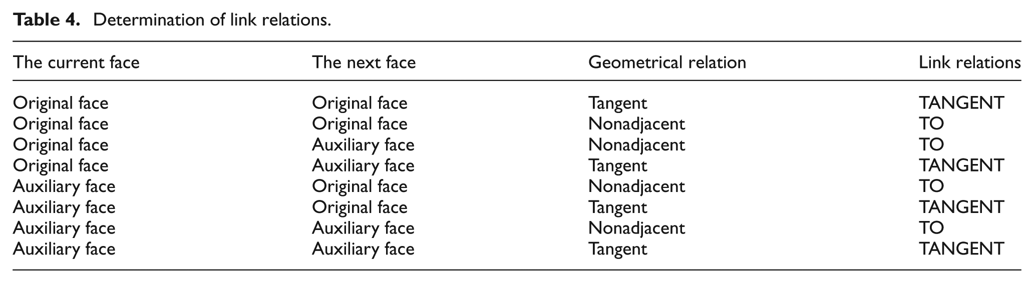
The link relations determine the tool move direction between the adjacent faces and are subdivided into TO, PAST and TANGENT. The PAST is shown in Figure 11. The determinations of link relations according to the type of the adjacent faces are listed in Table 4.
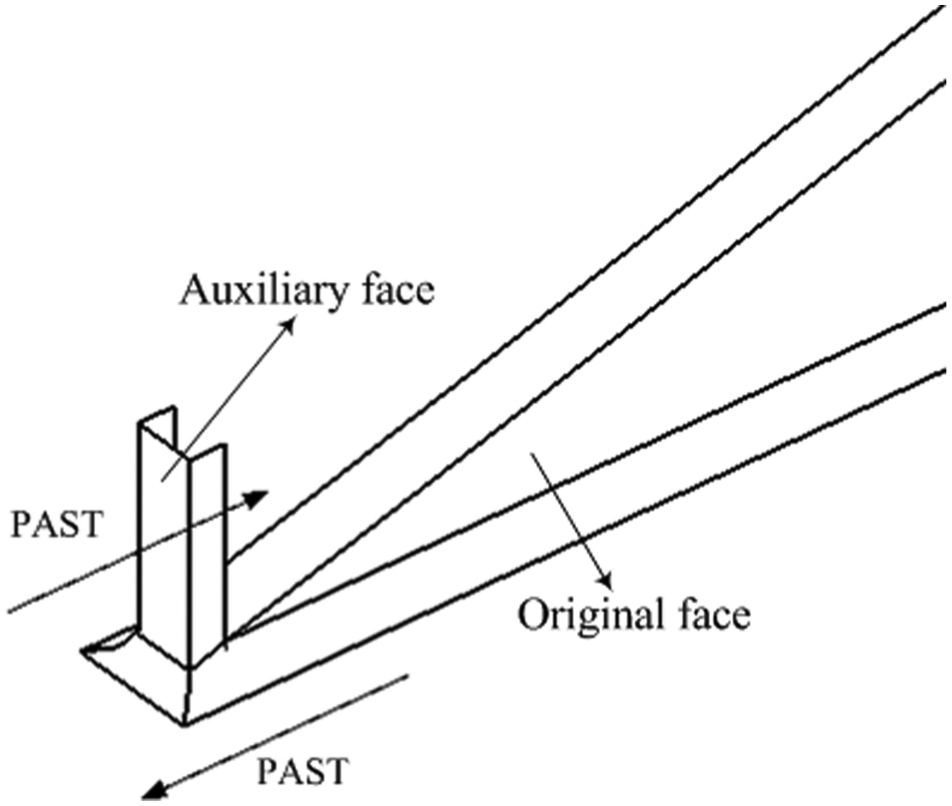
Link relation: PAST.
Determination of link relations.
Case study
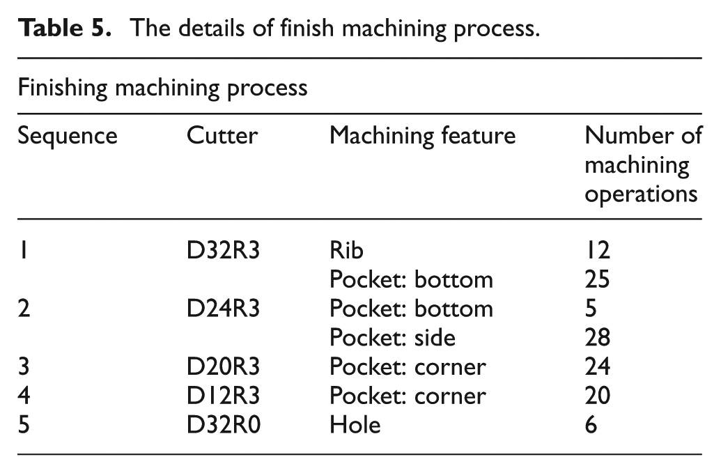
On the basis of this research, a pilot feature-based machining system has been developed based on CATIA V5®. An aircraft structural part as shown in Figure 12(a) is taken as an example to reveal the performance of the proposed method. This part is 562 mm long, 488 mm wide and 58 mm high and has 12 pockets, 11 ribs and 6 holes. The drive geometries for machining the part are constructed automatically. In order to display the generated drive geometries explicitly, only the drive geometries for pocket side milling are shown in Figure 12(b). The side milling tool paths which reference the constructed drive geometries are shown in Figure 12(c). For the purpose of demonstrating the significant improvement of the proposed method, the machining process and the comparisons between the proposed method and the traditional method are listed in Tables 5 and 6, respectively.
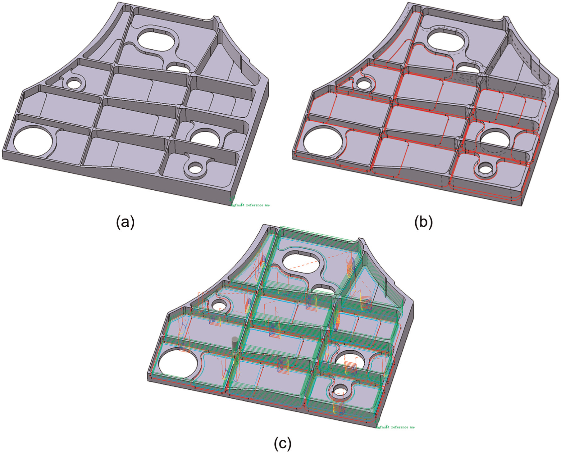
A case study of an aircraft structural part.
The details of finish machining process.
Comparisons between the proposed method and the traditional method.
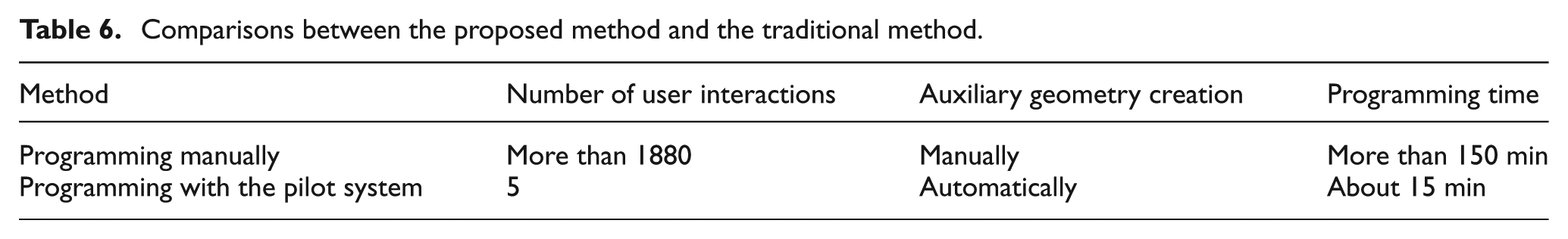
Traditionally, the drive geometries are created interactively with low efficiency and are error-prone. More than 1880 user interactions (mouse click and keyboard input) are required to accomplish the NC programming for finish machining which requires more than 150 min. Benefitting from the proposed method, only about 5 user interactions and 15 min are required to complete the same task. The NC programming efficiency is increased by 10 times evidently.
Some commercial CAM systems which have feature-based machining function have been issued, such as hyperMILL® from OPEN MIND, NX from Siemens PLM Software, CAMworks from Geometric and FeatureCAM from Delcam. The comparisons between these systems and the proposed method are shown in Table 7.
Comparisons between commercial feature-based CAM system and the proposed method.
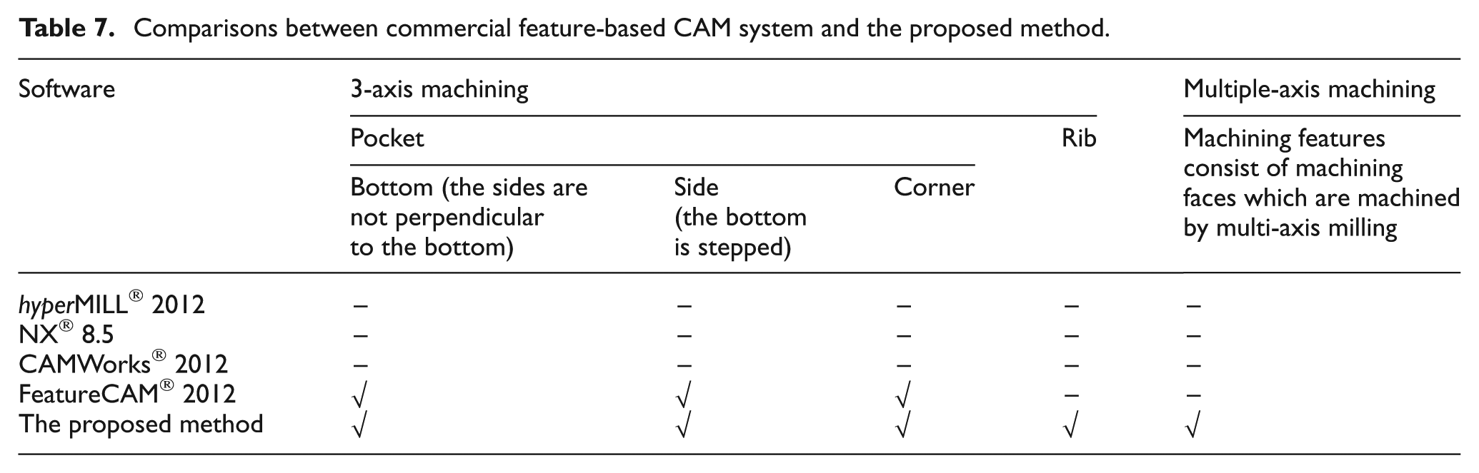
At present, the commercial CAM systems focus on 3-axis machining features. Even though it has been announced that hyperMILL and FeatureCAM are capable of generating tool path for multiple-axis machining features automatically, these features are indeed machined by three axes plus one additional fixed swing axis. For 3-axis pocket milling, almost all commercial systems can generate tool path for simple pocket features. However, the stepped pocket as shown in Figure 5 and the pocket with free-form surface sides as shown in Figure 6 are excess of their ability except FeatureCAM. For rib milling, these systems recognize the top faces of the rib features as the pocket bottoms which cause the rib top to be machined in the wrong way. In fact, the stepped pockets, free-form surface and rib feature are widespread in aircraft structural parts. Therefore, the commercial feature-based CAM system cannot meet the requirement of the NC machining of aircraft structural parts.
Conclusion
This article presents a drive geometry construction method for NC programming in aircraft manufacturing. Drive geometry is the bridge between the process planning and tool path generation. Due to the complex shape, the drive geometries of machining features for NC tool path generation have been destroyed. Hence, the output information of process planning cannot be used for tool path generation directly. By comparison with the traditional drive geometry creation interactively, this systematic method constructs the drive geometries automatically in accord with the machining process and the topological relationships of the machining features. And the created drive geometries correspond with the optimized machining process. The drive geometry preparing time and the consumption of computer memory are reduced significantly. As a result, the process planning and tool path generation are integrated seamlessly. A pilot feature-based machining system with the proposed method has increased NC programming efficiency (approximately 10 times).
Footnotes
Declaration of conflicting interests
The authors declare that there is no conflict of interest.
Funding
This work was supported by the National Natural Science Foundation Project of China (grant nos 50905087 and 51375239), the National Science and Technology Major Project of China (grant no. 2012ZX04010-041) and the Funding of Jiangsu Innovation Program for Graduate Education (grant no. CXZZ11_0225).