
Abstract
In computer-aided design for moldings, automatic generation of parting curves is a crucial design task that has an influence on the entire mold structure. This article proposes a hybrid approach for determining the parting curves of free-form computer-aided design models. Based on the analysis of the geometric properties of specific entities and mathematical conditions, different sets of moldable surfaces for two-half molds and side cores are identified. All surfaces that do not contribute to the parting curves can be subtracted from these surface sets. The proposed parting curve is generated based on the combination of both the outermost boundary edges and the visible silhouette segments of the relevant surfaces. By the techniques of silhouette detecting, edge projecting, and ray testing, the proposed algorithm overcomes the problems found in conventional research that cannot guarantee that the outermost curves generated are the actual silhouette of a free-form surface. In addition, by eliminating all irrelevant surfaces and without using the surface approximation method, the proposed approach achieves the goals of obtaining high accuracy coupled with high performance. Two examples of industrial models are used to demonstrate the performance and robustness of the proposed algorithm. The approach is generic in nature, which allows it to be applied to any complex geometry in three-dimensional mold design.
Introduction
In injection molding, automatic determination of requisite geometric data, such as parting direction, parting curves, parting surfaces, undercuts, and side cores, is a critical task which affects the entire structure of the mold. The increasingly diverse use of complex parts with free-form surfaces has meant that the development of algorithms that automatically determine the above-mentioned geometric data has become an important issue in the field of mold design.
One of the earliest research studies in this area by Ravi and Srinivasan 1 established a set of nine criteria which could help a mold designer make rational decisions regarding parting curves and parting surfaces. Algorithms that recognize undercut features and determine the optimal parting direction have also been developed. Based on feature taxonomy, characteristics, and geometric entities, Fu et al. 2 introduced an algorithm related to the determination, classification, and recognition of feature parameters for undercuts. Ye et al. 3 proposed a hybrid method in which the extended attributed face-edge graphs (EAFEGs) and the cut-sets of sub-graphs were developed to recognize various undercut features for molded parts with planar, quadric, and free-form surfaces. Lu and Lee 4 introduced the concept of grid line and column insertion test, geometric and topological information, and three-dimensional (3D) ray detection, respectively, to recognize undercut features. Moreover, Ismail et al. 5 proposed an approach to recognize cylindrical-based features based on an edge-boundary classification technique. Khardekar et al. 6 described an algorithm using the implementation of a Gauss map on the geometry of the molded parts to identify and display undercut features. Building upon these techniques related to the recognition of undercut features, Fu et al. 7 proposed an algorithm that determined the optimal parting direction in injection-molded parts by the number of undercut features and their corresponding volumes. Furthermore, Chen et al. 8 presented a “visibility map” to determine surface visibility in both global and local interference, which was then used to determine the optimal parting direction of a 3D model. Chen et al. 9 proposed a method in which three possible parting directions were defined by the surface normal vectors of a bounding box. The dexel model and fuzzy decision making were then used to estimate the feasible parting directions. Additionally, Dhaliwal et al. 10 described an approach to identify the global accessibility cones of each face on a polyhedral object, and the set of directions from which they were accessed.
Automatic determination of parting curves and parting surfaces has been the central issue in mold design. Based on the relationship of geometric entities, a variety of techniques have been developed to achieve this end. Tan et al. 11 presented the concept of visible and invisible surfaces for surface classification, in order to determine the common edges for parting line generation. Weinstein and Manoochehri 12 proposed a method that used convex and concave regions to determine the allowable draw range and the parting curve location based on multiple objective function criteria. Moreover, Fu et al. 13 used the maximum external edge loops between the core- and cavity-molded surface groups to generate a parting curve. Chakraborty and Venkata Reddy 14 presented a method to determine the parting line and parting surface for a two-piece permanent mold that was based on the combination of the surface area of the undercut, the flatness of the parting surface, and the draw depth. In addition, Wong et al. 15 proposed an uneven slicing approach to find the feasible parting curves of a computer-aided design (CAD) model by a set of cutting planes. The best parting curve was evaluated based on the criteria described by Ravi and Srinivasan. 1 Furthermore, Paramio et al. 16 evaluated the demoldability of injection-molded parts through the slicing of their CAD models, which could then be used to determine feasible parting lines. Through the determination of parting lines, Fu et al. 17 found parting surfaces by extruding the parting curves to the boundary of the building blocks of the core and the cavity. Additionally, Li and colleagues18,19 proposed an approach to evaluate the extrudability of parting lines. For the portions of the parting lines that were not extrudable, a sub-division technique was employed to generate parting surface patches.
Many different approaches of generating side cores, pins, and other components of mold structures have also been proposed. Ye et al. 20 presented a methodology that used surface properties, the EAFEG representation, the cut-sets of sub-graphs, and Boolean operations to automatically generate a side core for each undercut. Banerjee and Gupta 21 employed the retraction space of each undercut facet to identify the shapes of the side cores. The undercut facets were grouped into undercut regions according to the discrete set of feasible and non-dominated retractions, after which the geometry of individual side cores could be obtained. Fuh et al. 22 presented a prototype system structured by several functional modules as specific add-on applications on a commercial CAD system for the development of a semi-automated die casting die design system. Fu 23 used the concept of surface visibility, demoldability, and moldability to identify the surfaces that were molded by side cores. Furthermore, Ran and Fu 24 described an algorithm for automatic design of internal pins via the recognition of undercut features. After identifying the inner undercuts and extracting the related surfaces, the internal pins for the molding of the inner undercuts could then be designed.
Zhow et al. 25 introduced a fast boundary element method (BEM) approach for analysing mold cooling. In their method, a dynamic allocation strategy of integral points was built to generate the BEM matrix based on the Gaussian integral formula. In addition, Elyasi et al. 26 described a new die set to improve the corner filling of dies in hydroforming of cylindrical stepped tubes. Accordingly, the molding process of the proposed die set was simulated and the filling properties of the die cavity were also investigated. Most recently, Ranjit et al. 27 proposed an approach to automatically identify undercut features via the concept of visibility and accessibility. Those undercut features were then separated into smaller simple ones through a rule-based algorithm for further determination of their releasing directions.
The development of CAD research for mold design has also been connected to the field of manufacturability and manufacturing costs. Bidkar and McAdams 28 presented a feature recognition method based on the elemental cubes to assess the critical manufacturability information of injection-molded parts, and Denkena et al. 29 introduced a method in which a CAD-based application of the calculation tool “visual form calculator” was used to generate and analyze CAD models of mold cavities in order to compute tool accessibility and manufacturing costs.
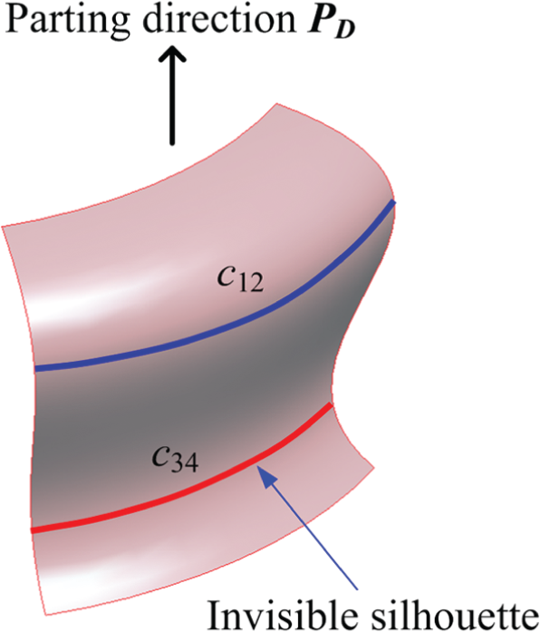
As seen in the literature summarized above, various approaches have been proposed to automatically determine the parting curves for mold parts. Except for a few that used heuristic, fuzzy, or sliced techniques, most existing methods identified the potential parting curves through separating segments between different moldable surface groups. The implementation of these approaches was primarily based on the visible, partially visible, and invisible properties of the surfaces; however, these approaches were effective only for simple models of which their outermost segments were naturally either the sharp or the boundary edges of the surfaces (Figure 1(a)). For many complex models, their free-form surfaces have both visible and invisible properties due to the inconsistency of normal directions at different points (Figure 1(b)). Thus, the separating segments are not merely their real edges and are therefore not easy to extract. In these cases, the most effective solution is determining the silhouettes that split different surface regions exactly. The disadvantage to this approach is that if these silhouette-detecting algorithms are based on the surface approximation techniques which incorporate a vast amount of polygonal facets, the number of resultant silhouette segments is unnecessarily large. These techniques thus lead to an increase in calculation time and manufacturing costs, which runs against the broader goal of optimal mold design. Moreover, not all surfaces contain silhouette segments and not all silhouette edges are suitable for use as parting curves (Figure 2). Some of these silhouette segments are invisible to the parting direction
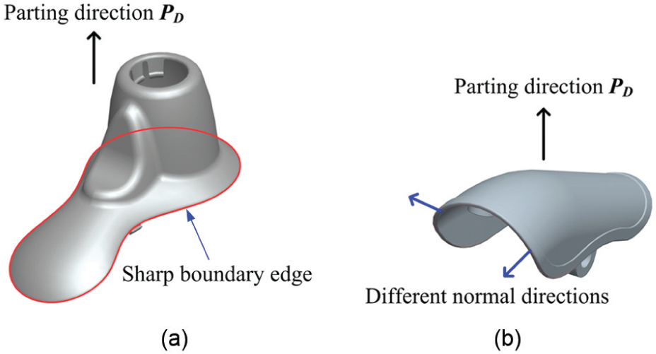
(a) A part with sharp boundary edges and (b) a part without sharp boundary edges (thus a silhouette has to be found for molding purpose).
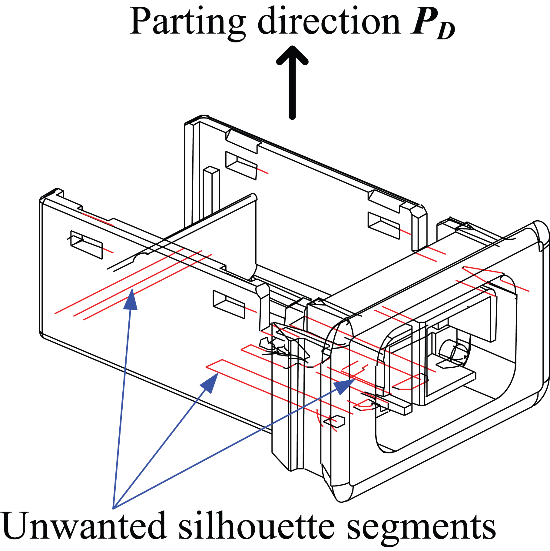
Unwanted silhouette segments.
Geometric analysis and surface classification for molding
In terms of design procedures for molding, the first two issues to be addressed are geometric analysis of CAD entities and the classification of surfaces into different sets. These activities can be considered as the prerequisite tasks that are necessary to be carried out before implementing the proposed approach of automatic parting curve generation. The following sections will discuss the conditions under which a surface can be molded for two-half molds or side cores.
Geometric analysis of moldable surfaces
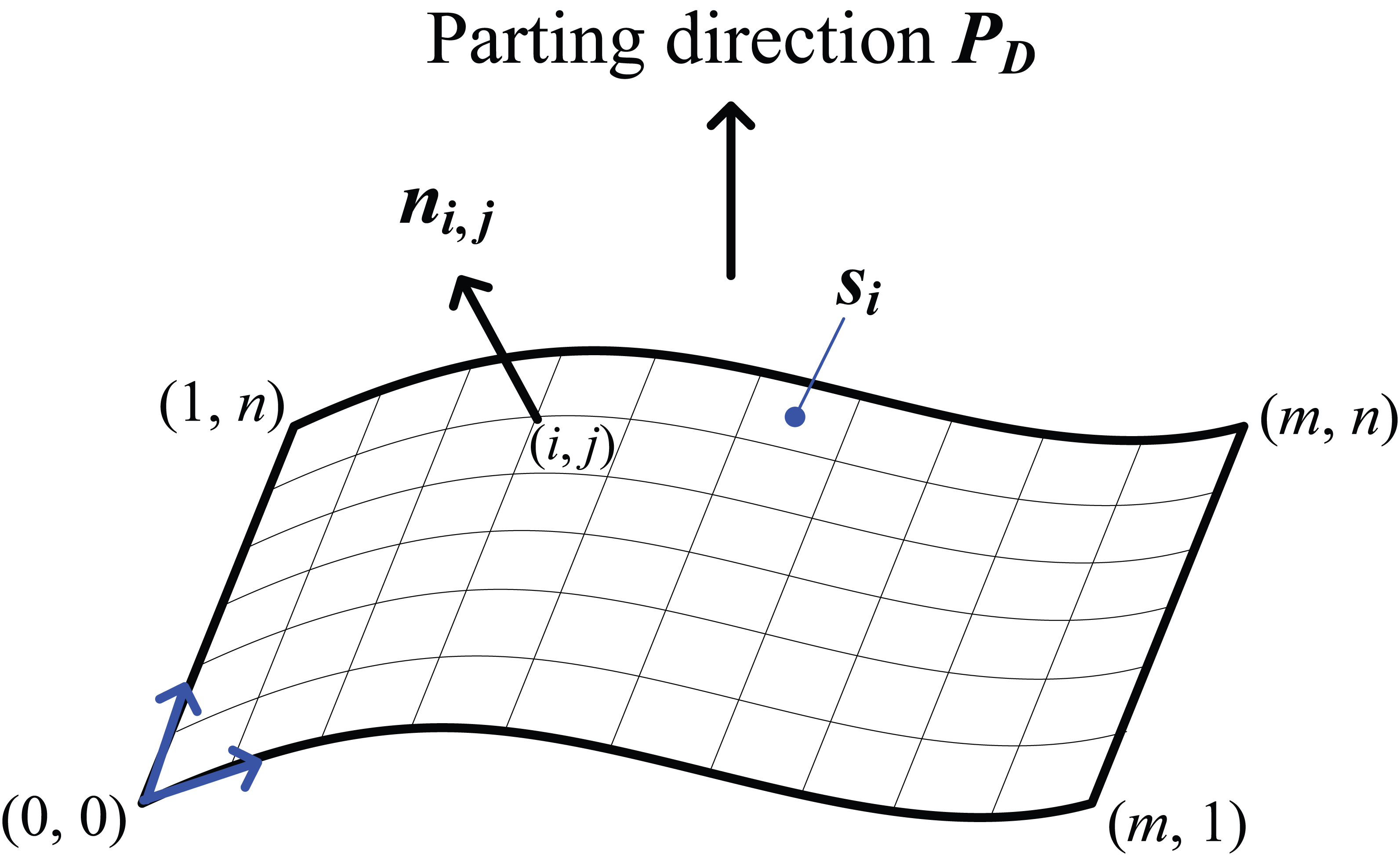
In order to describe the algorithm, the geometric and topological analysis of CAD entities is presented below. Based on the B-rep description, a closed-loop CL of a surface si is a group of edges bounding the whole surface to form its closed boundaries. A particular surface may have one or several closed loops depending on the presence of “hole features” within it (Figure 3(a)). As shown in Figure 3(b), closed loops of a surface can be classified into external CL, denoted as ECL, and internal CL, denoted as ICL, according to their position. An ECL forms the external boundary of the surface, and thus, there is only one ECL per surface. On the other hand, an ICL is the internal interaction boundary of the surface and there can be more than one.
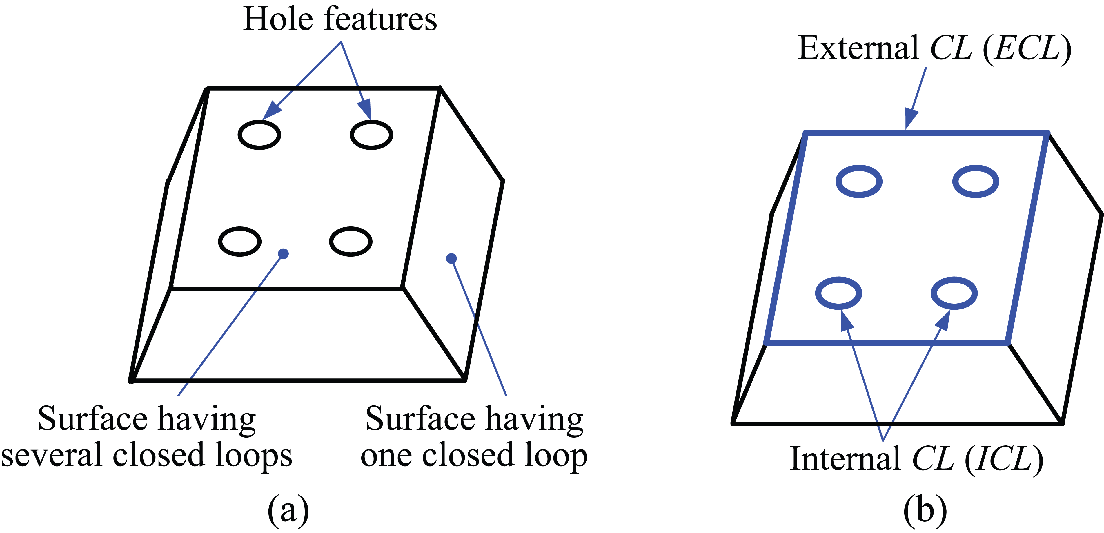
(a) Closed loops of a surface and (b) external and internal closed loops.
In addition, the definition of moldable surfaces, which are extended from those of surface visibility and moldability mentioned in Weinstein and Manoochehri,
12
is also described below. The presentation of moldable surfaces focuses on the following three types: planar surfaces (first-order surfaces), quadric surfaces, and free-form surfaces (third-order surfaces or higher). Suppose that si
is a surface of model M and

The physical meaning of equation (1) is that rays parallel to parting direction
For planar and quadric surfaces, the normal vector of a point on these two types of surface possesses an exact direction and thus it is easy to check whether equation (1) is fulfilled (Figure 4). However, for a free-form surface, a sub-division method has to be employed: the surface is divided into small patches of equal distances in parametric coordinates u and v, and the normal vector
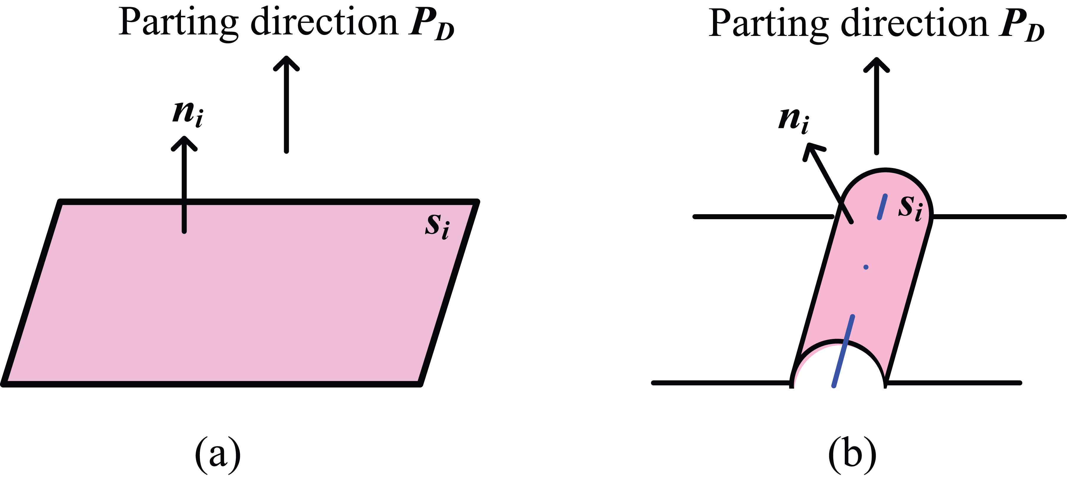
(a) Moldable planar surface and (b) moldable quadric surface.
A moldable free-form surface.
For cases where the surfaces are those of revolution, the method to determine moldable surfaces is quite different: the axis of revolution is used instead of the normal vector to determine whether a revolution surface can be molded. In general, cylinders and cones are considered in the design of industrial parts. When the surface is a cylinder, the equation to determine moldability is

where
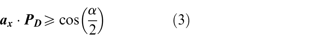
where
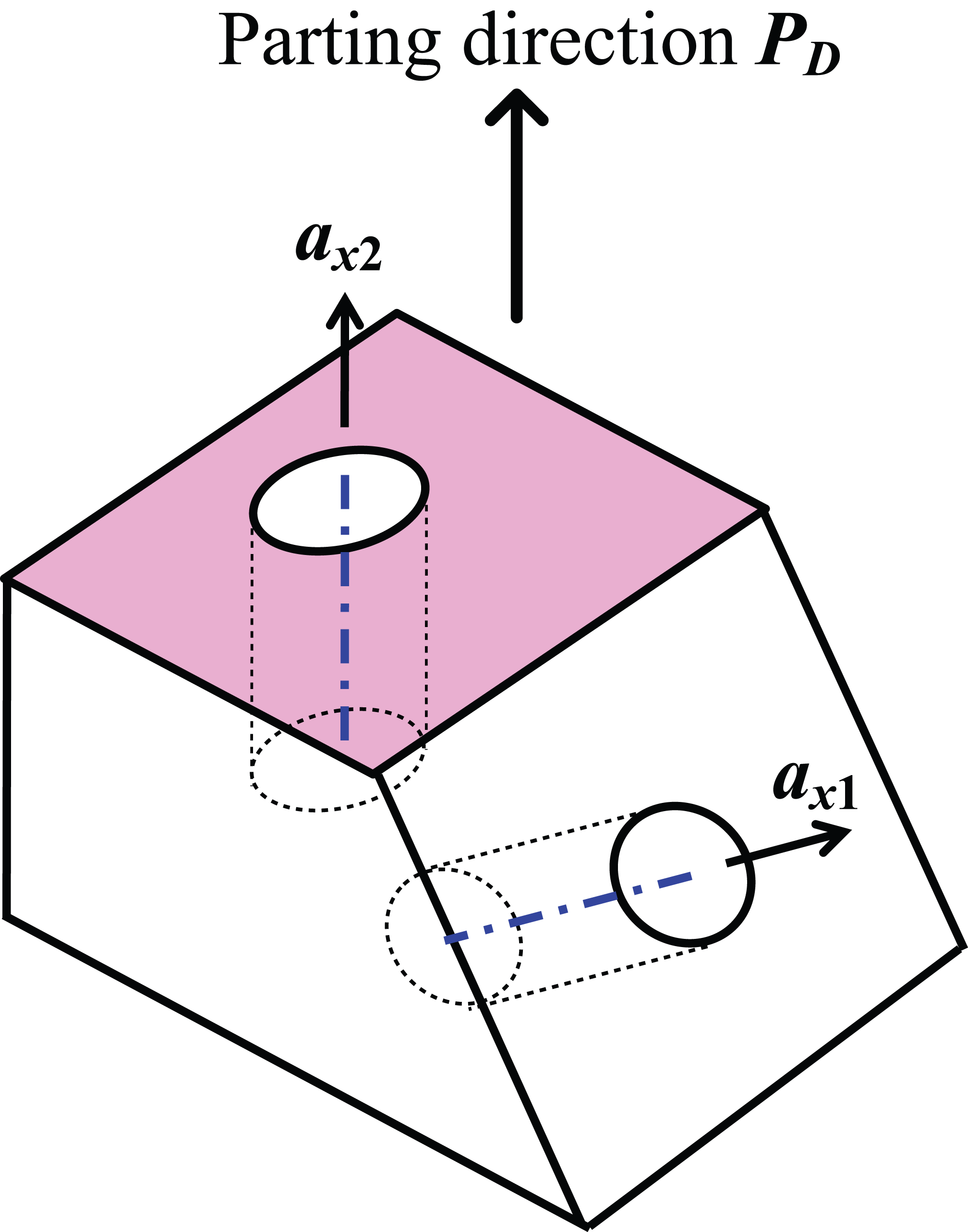
Moldable and unmoldable cylindrical surfaces.
(a) Limited angle of axis of a moldable conical surface and (b) moldable and unmoldable conical surfaces.
Surface classification for molding
Equations (1)–(3) listed above are used to examine all surfaces of a part, and the following three cases can be identified:
Case 1. If each of the normal vectors on a surface si
satisfies either one of the three equations, then si
is defined as a moldable surface in parting direction
Case 2. If equation (1) or (2) or (3) are not always met at every point of surface si due to the inconsistency of normal directions, then si is identified as a dual surface that has a visible portion and an invisible portion at the same time (see Figure 8(b)).
Case 3. If all three equations fail for all normal vectors on a surface si
, then the surface is not moldable in direction
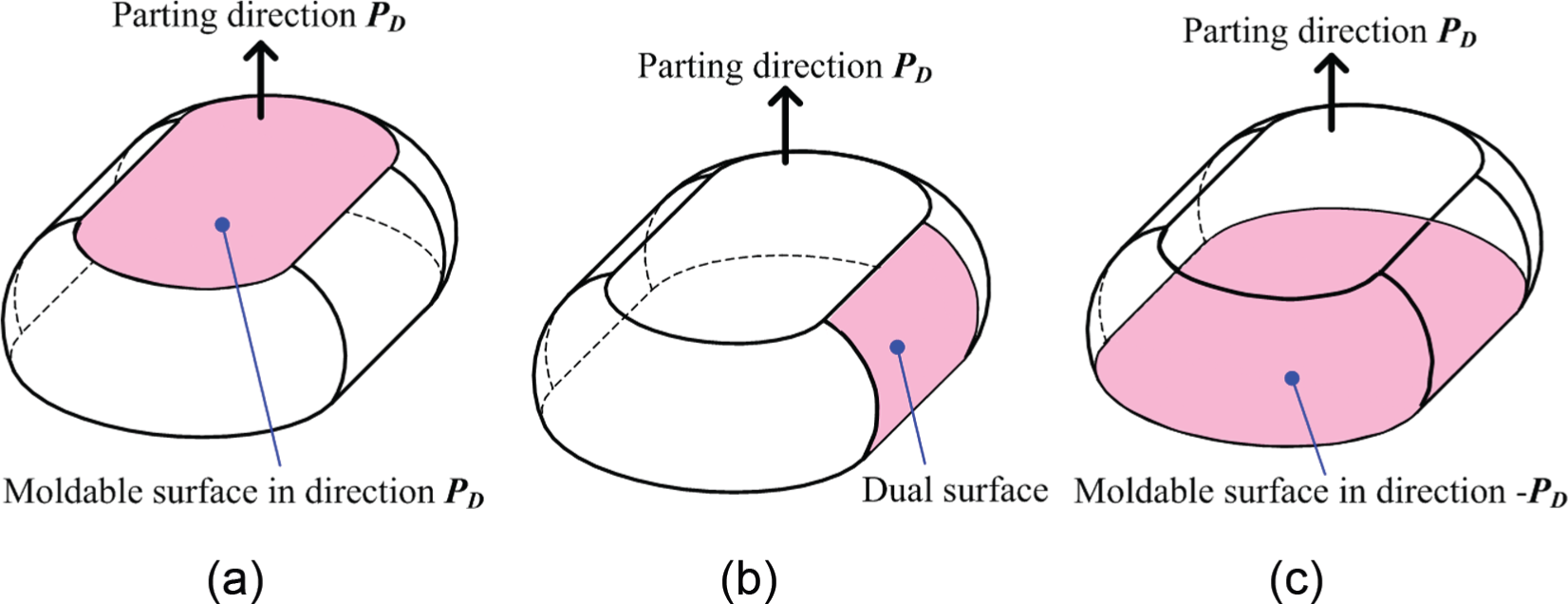
(a) Moldable surface in direction
All surfaces identified from Case 2 are classified into the set “dual moldable surfaces (MSD).” For surfaces that fulfill Case 1, they are moldable for a half mold or side cores depending on their position. If these surfaces are of undercuts, they are classified as “moldable surfaces for side cores (MSC).” Otherwise, they are identified as “moldable surfaces for a half mold in direction
In order to further categorize moldable surfaces (Case 1) into MSP or MSC, a ray test is employed. First, all moldable surfaces and surfaces of the MSD set are collected and stored in a so-called S-table. Each moldable surface si
is then tested in sequence by rays to determine whether it is obscured by other surfaces included in the S-table. Each ray is produced from the end and the middle point pi
on each edge ei
of this test surface si
, along direction
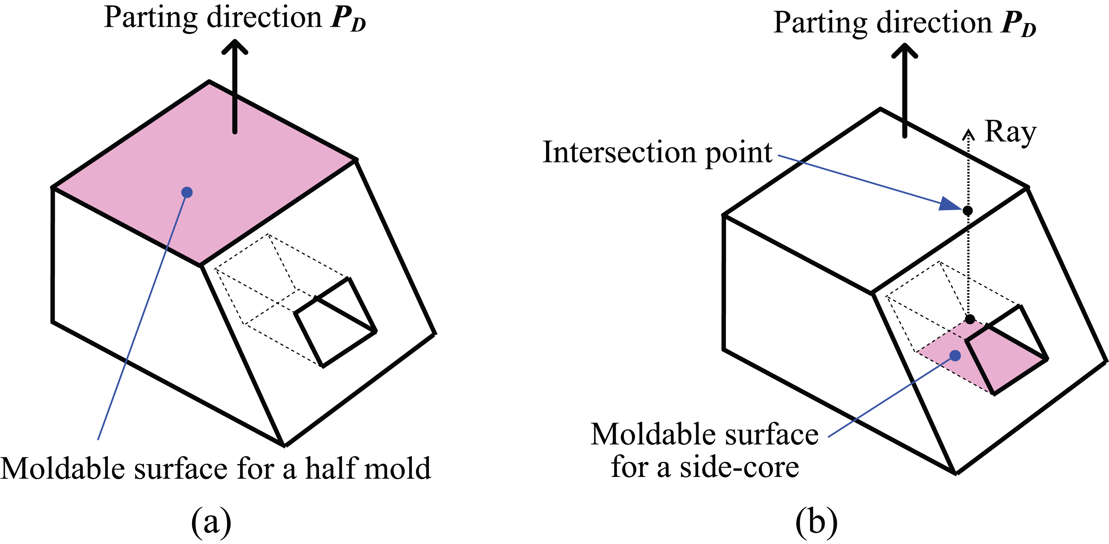
(a) Moldable surface for a half mold (in direction
The key of ray testing is to determine whether the ray and the surface intersect. If the surface in the S-table is determined to be a simple type, such as a plane or a revolved surface, the implicit form is used to describe the surface


where

which yields
For a free-form surface, the following parametric form is used

and the following equation is considered

which yields
Equation (4) or (5) is used to evaluate the occurrence of an intersection between the ray and the test surface. Based on the results of equation (4) or (5), the test surface can be classified as MSC or MSP as above.
For a surface identified as falling under Case 3, it is defined as a moldable surface in direction −
Procedure to classify the surfaces into different sets.
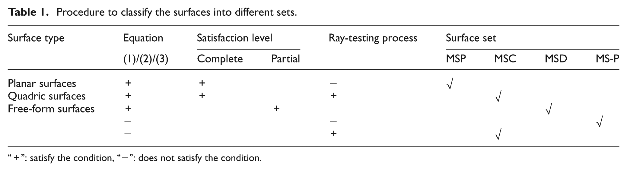
“+”: satisfy the condition, “−”: does not satisfy the condition.
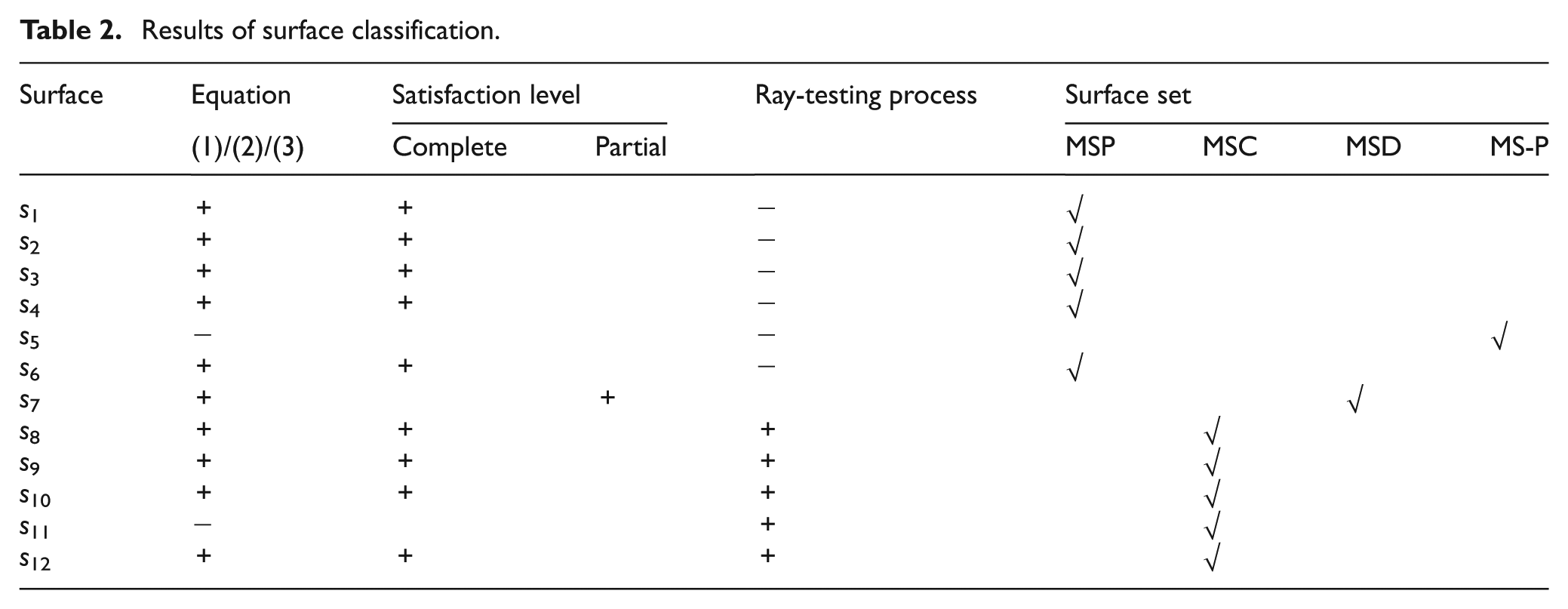
The application of Table 1 is illustrated by an example model in Figure 10. There are 12 surfaces, denoted from s
1 to s
12, and all of them are planar surfaces except surface s
7. Based on the given parting direction
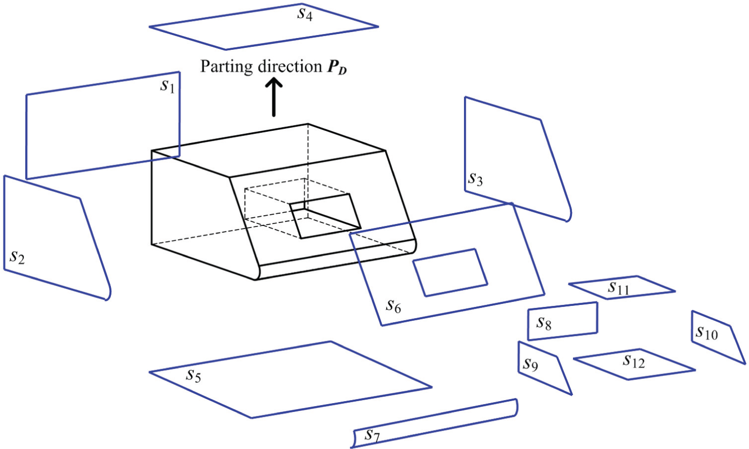
Simple model and its surfaces.
Results of surface classification.
Determination of parting curves
In the proposed algorithm, the automatic generation of parting curves involves the following research tasks (see Figure 11): rejection of irrelevant surfaces, retrieval of relevant surfaces and their boundaries, extraction of silhouettes of dual free-form surfaces, determination of silhouette segments, and formation of closed loops. Detailed discussion of these tasks will be covered in the subsequent sections.
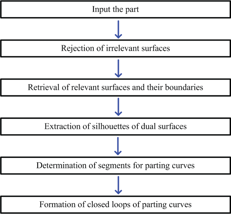
Procedure for automatic generation of parting curves.
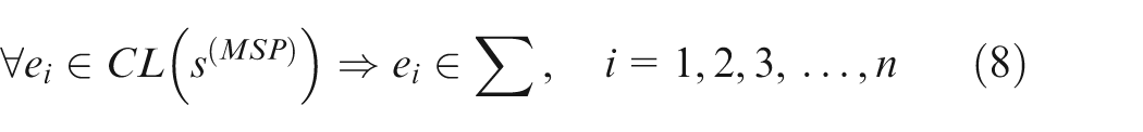
Rejection of irrelevant surfaces
The task of rejecting irrelevant surfaces aims to reject those surfaces that do not contribute to parting segments. Surfaces of the MSP, MSD, and MSC sets, which are associated with the parting direction
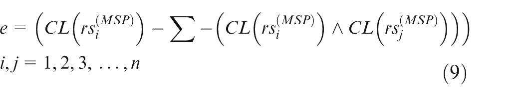
First, all edges of the surfaces belonging to the MSP set are checked. An edge e is determined to be a common edge (
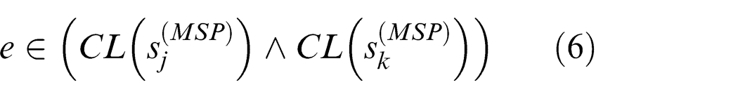
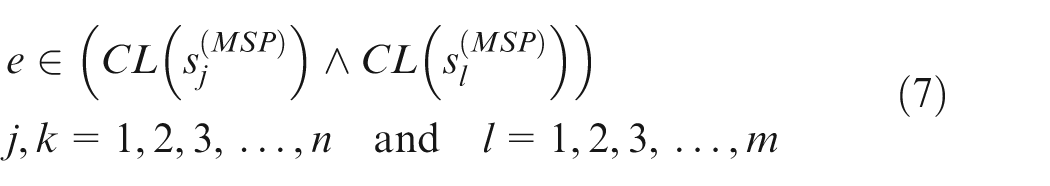
where
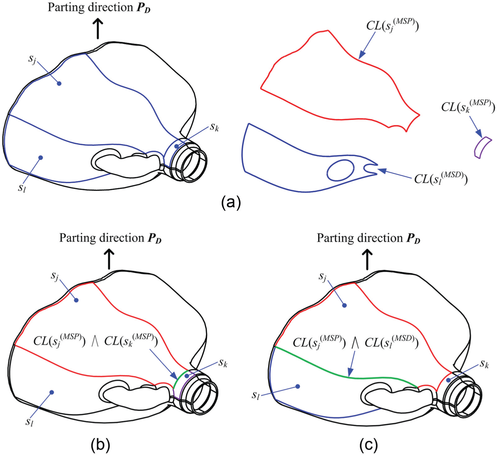
(a) Closed boundary loops of surfaces, (b) common edge of two surfaces of the MSP set, and (c) common edge of a surface of the MSP set and another of the MSD set.
Let Σ be the set of common edges
where
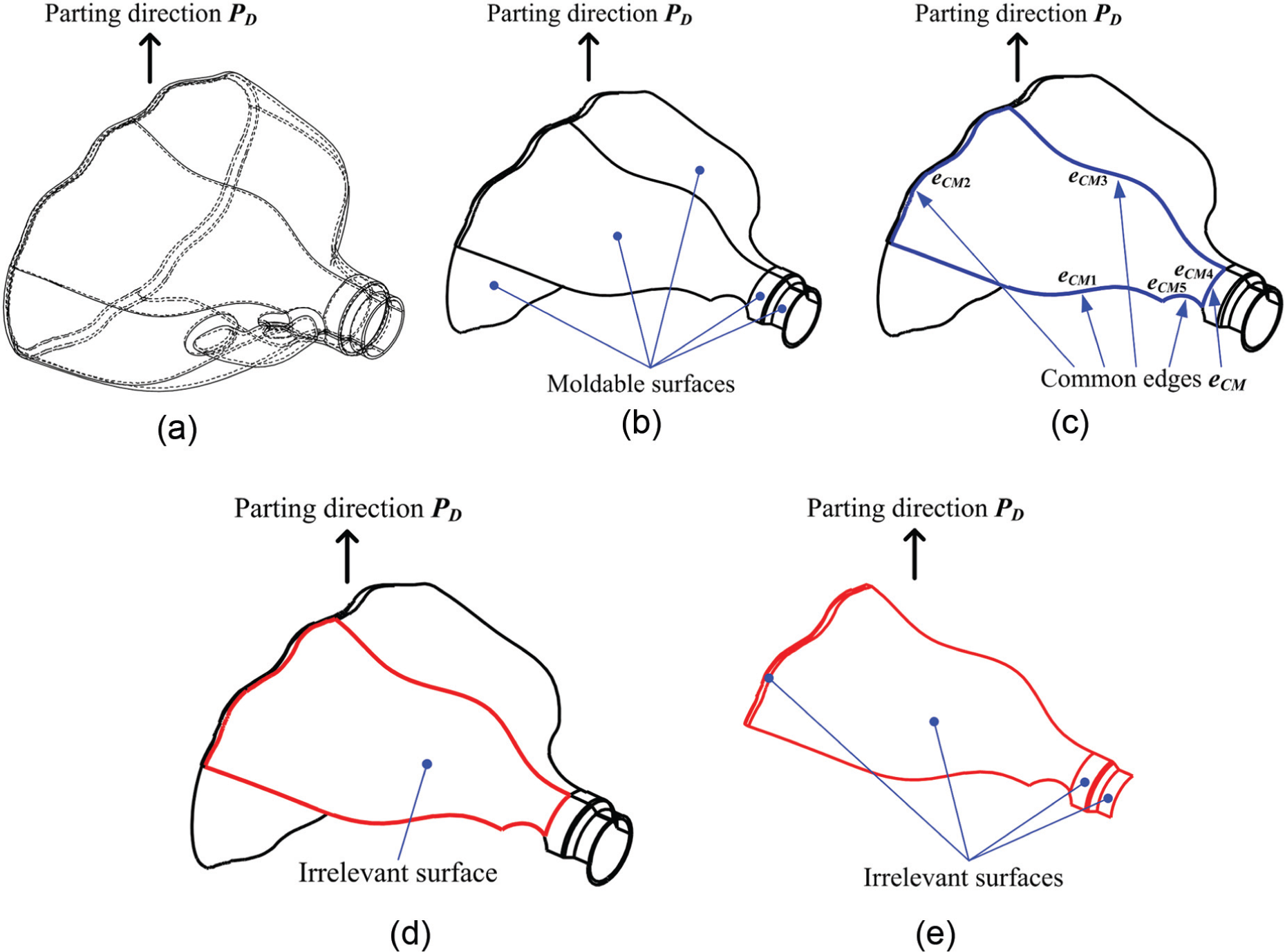
(a) Part model, (b) moldable surfaces, (c) common edges
Retrieval of relevant surfaces and their outermost boundaries
Retrieval of relevant surfaces is the second task in the generation of parting curves. In contrast with irrelevant surfaces, relevant surfaces are surfaces of the MSP set that actually contain segments that contribute to the parting curve. In general, relevant surfaces are those remaining in the MSP set after rejecting all of the irrelevant surfaces. Since the entire area of a relevant surface is visible along parting direction
where
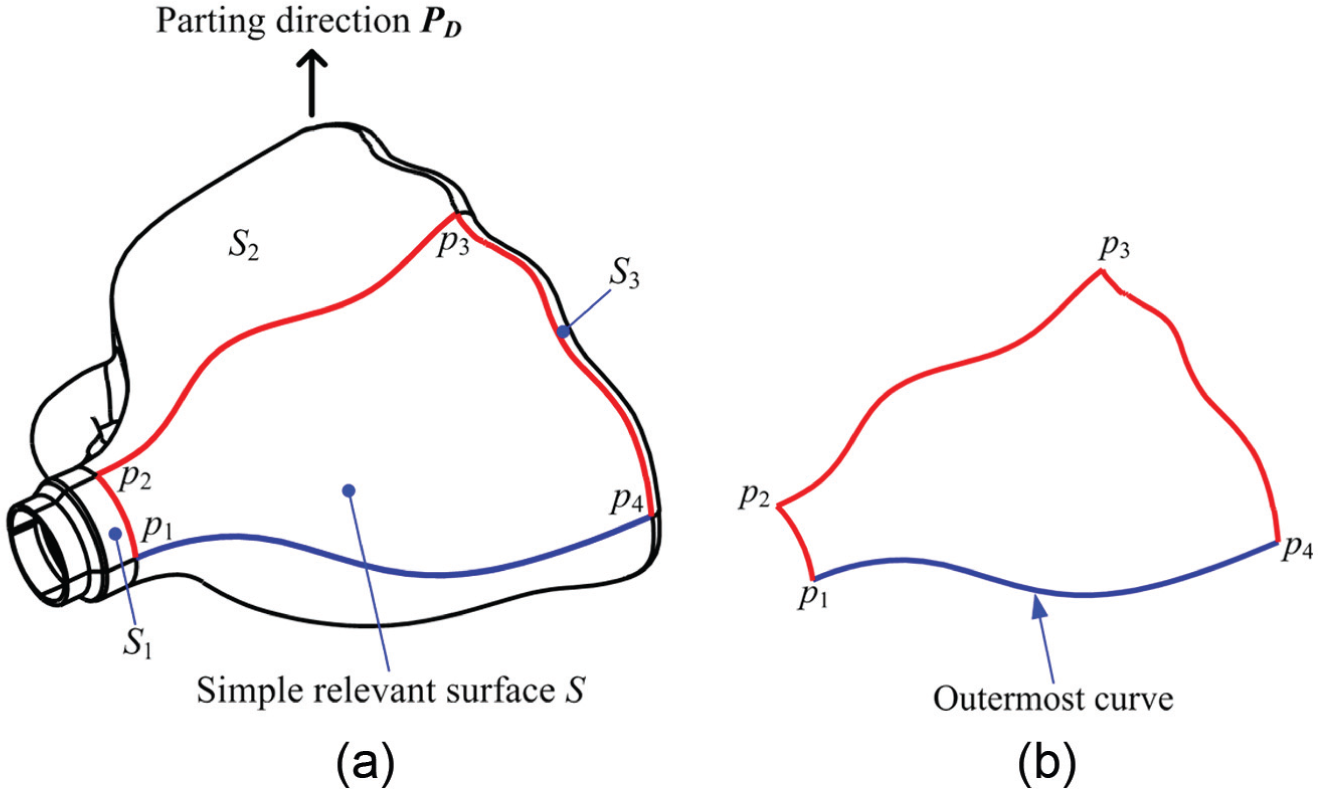
(a) Relevant surface S and (b) outermost curve of surface S.
Extraction of silhouettes of free-form surfaces
Determination of silhouette segments of dual moldable surfaces is the next task in the proposed algorithm. Different from relevant surfaces, the outermost segments of dual moldable surfaces in the MSD set are not always their boundary edges and are very difficult to be identified. Therefore, the determination of the outermost segments of a dual moldable surface is done via the extraction of silhouettes, which separate the surface into visible and invisible regions.
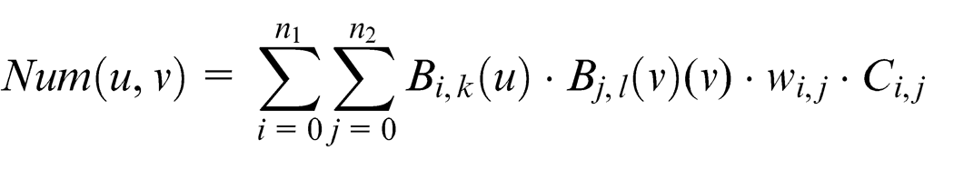
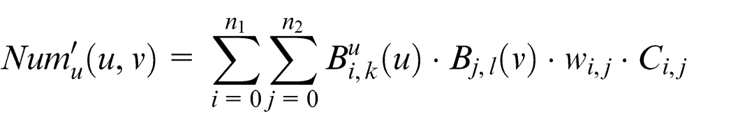
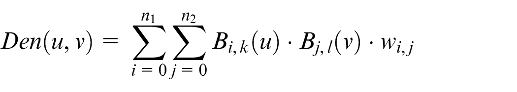
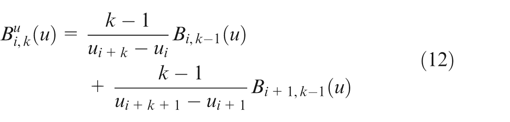
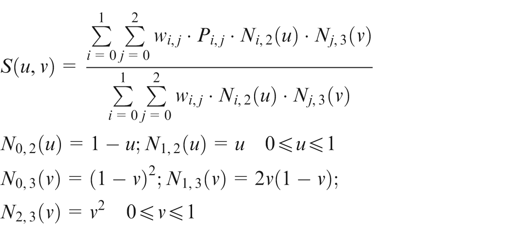
In this task, each dual moldable surface of the MSD set is represented in a non-uniform rational basis spline (NURBS) form. NURBS is the standard for geometry description in CAD/computer-aided manufacturing (CAM)/computer-aided engineering (CAE). It is basically a function of two parameters u and v that maps a surface in 3D space. The shape of the surface is determined by control points. Assuming that
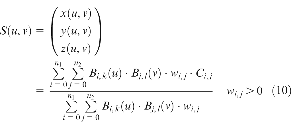
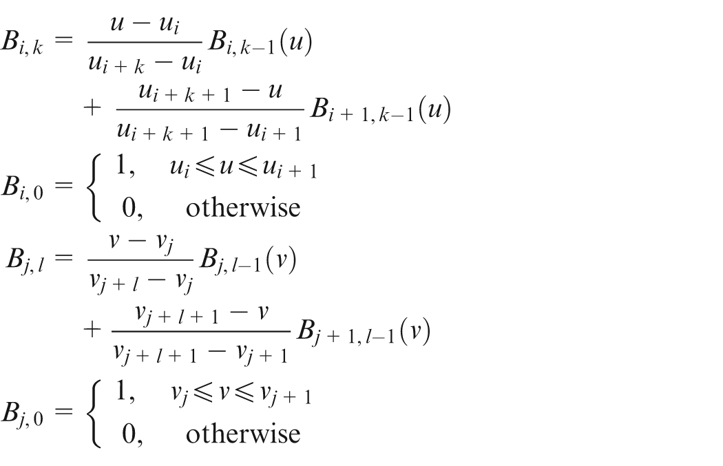
where Ci,j is the control point, wi,j is its corresponding weight, n 1 and n 2 are the number of control points in directions u and v, and Bi,k and Bj,l are B-spline basis functions defined in u and v.
The silhouette of a free-form object is typically defined as the set of points on the object’s surface where the surface normal is perpendicular to the vector from the viewpoint. A point on surface

From equation (10), the numerator of surface
and its partial derivative with respect to parameter u is
The denominator of surface

and its partial derivative with respect to parameter u is
where the derivative
Thus, the partial derivative of
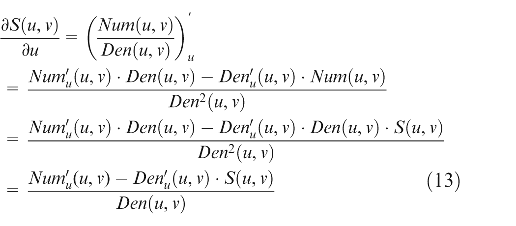
Similarly, the partial derivative of
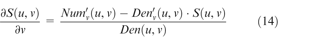
The surface normal
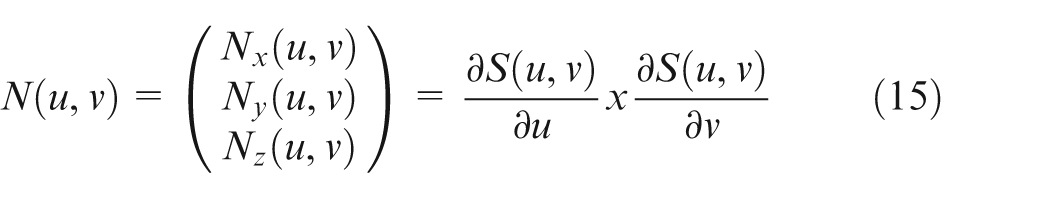
In general, to facilitate the design of parting curves, the parting direction
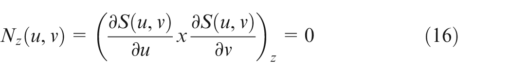
Equation (16) is a polynomial equation of two variables u and v. In this scenario, the number of equality constraints is smaller than the number of variables. Its zero-solution set can be computed based on the convex hull and sub-division properties of rational spline functions. A set of discrete points approximating the zero set is generated by recursive sub-division based on the Newton–Raphson iteration with a given small tolerance ε. The method to solve a general system of m polynomial equations of n variables is described in the article presented by G. Elber and M.S. Kim. 30
Figure 15 shows a cylindrical surface and its silhouette found by applying equation (16). The information of the order, the number of control points, and the knot values in u and v directions are (2; 2; 0, 0, 1, 1) and (3; 3; 0, 0, 0, 1, 1, 1), respectively. Control points and corresponding weight factors are as follows:
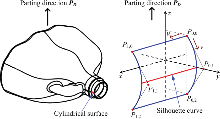
A cylindrical surface and its silhouette curve.
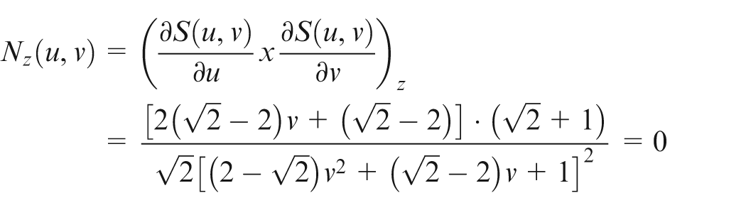
Applying equations (11)–(16) to determine the z component of the normal vector,
Parameters u and v are thus identified as v = 0.5, u = [0 → 1]. By substituting u and v into the equation of the cylindrical surface, the equation of the silhouette can be found as (u, 1, 0), where the value of u varies from 0 to 1 (see the red curve in Figure 15).
Determination of silhouette segments
The silhouette segments extracted from dual molded surfaces in the MSD set are used for the formation of parting curves by connecting them to the outermost boundaries of relevant surfaces. However, not all silhouette segments detected by the algorithm discussed in the previous section are suitable for parting curves. Some of these segments are invisible to the parting direction
Invisible silhouette segment.
To determine which silhouette segment or which part of the silhouette segment is suitable for forming the parting curve, a combination of an edge-projection technique and a ray test is applied, where the edge-projection technique is used to determine the outermost silhouette segments and the ray test is to find the visible curve segments along parting direction
(a) Projected entities of silhouettes and (b) outward vectors.
Next, all intersection points between the outward vectors and the projected entities are found. If an intersection point lies on the positive direction of the outward vector, the corresponding end point and intersection point are denoted as positive points (e+ and i+, respectively, see Figure 18(a)); otherwise, they are denoted as negative points (e− and i−, respectively, see Figure 18(b)). In the case where the outward vector does not intersect with any projected entity, the corresponding end point is denoted as a zero point e 0 (Figure 18(c)).
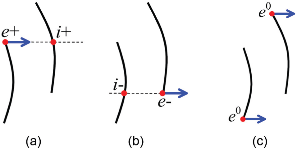
(a) Positive points, (b) negative points, and (c) zero points.
Based on the determination of positive, negative, and zero points, the projected entities denoted by e 0 i+, e 0 i−, e−i+, e−e−, and i+i+ are then identified as the outermost ones. They are basically entities on the projection plane that can be seen directly when viewed from outside along the opposite direction of the outward vectors. Table 3 shows all types of the projected entities and the outermost ones.
Projected entities and their outermost segments.
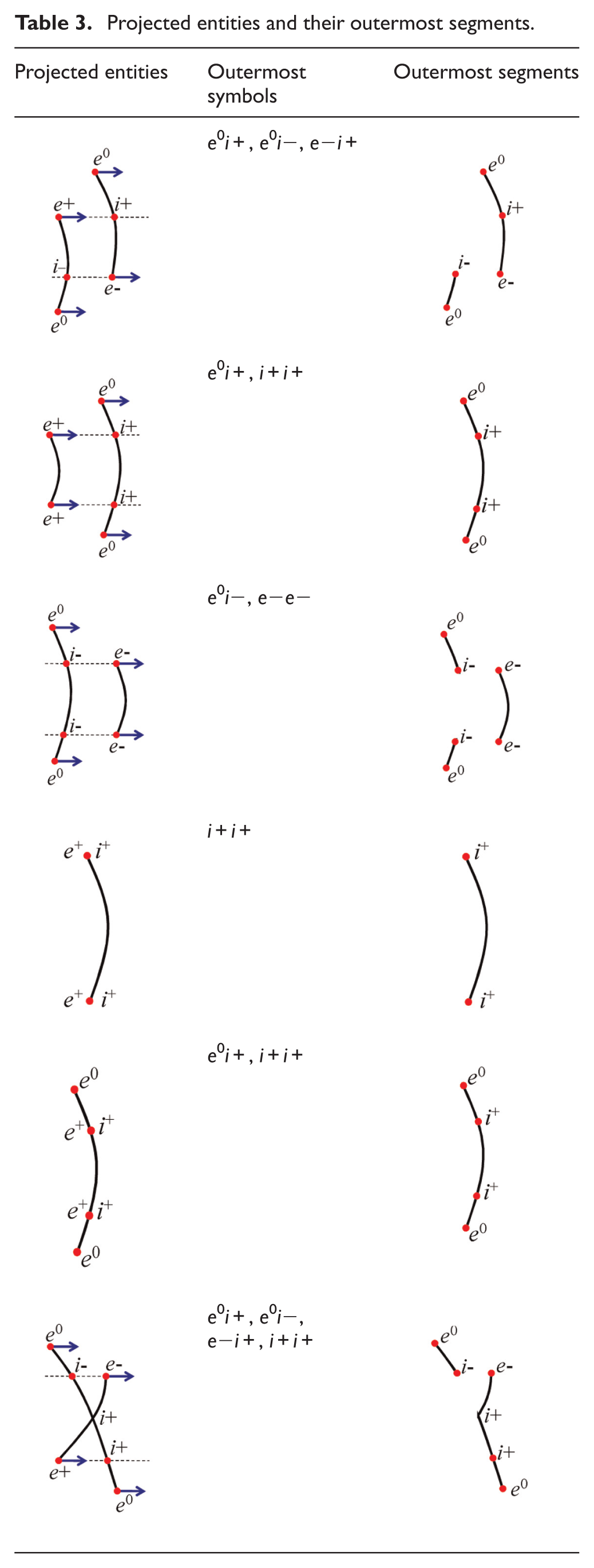
The next job is to find silhouette segments corresponding to the outermost projected entities based on the cases listed in Table 3. Figure 19(a)–(c) shows projected entities that are “separating,”“overlapping,” and “intersecting,” respectively. According to Table 3, entities denoted by e 0 i+, e 0 i−, e−i+, e−e−, and i+i+ are identified as the outermost projected entities, and thus, silhouette segments represented in blue are deemed to be the corresponding outermost ones.
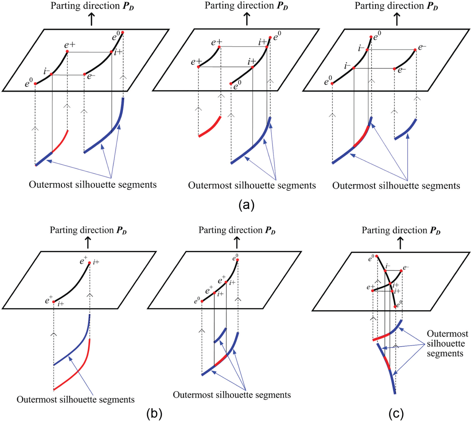
Cases of projected entities and corresponding outermost silhouettes: (a) separating entities, (b) overlapping entities, and (c) intersecting entities.
Finally, the ray test is applied to all outermost silhouette segments found from the above steps. Through the ray test, segments obscured by surfaces of the MSP set are disqualified as candidates for the parting curve. In other words, only the outermost silhouette segments that are visible from the parting direction
Formation of closed loops
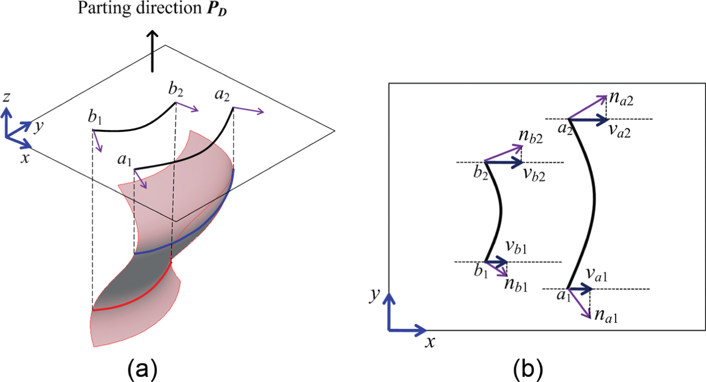
The last issue in determining parting curves in the proposed algorithm is to form closed loops based on the outermost boundaries of relevant surfaces and outermost-visible silhouette segments of dual moldable surfaces. Normally, outermost edges of adjacent surfaces are connected together at their corresponding end points to generate the continuous segments of parting curves. As shown in Figure 20(b), two outermost boundary edges of a relevant surface s 1 and its adjacent surface s 2 are connected at their end point p 1. Similarly, the outermost boundary edge of surface s 3 is also connected to the silhouette segment of a dual surface s 4 at their common end point p 2 (Figure 20(c)).
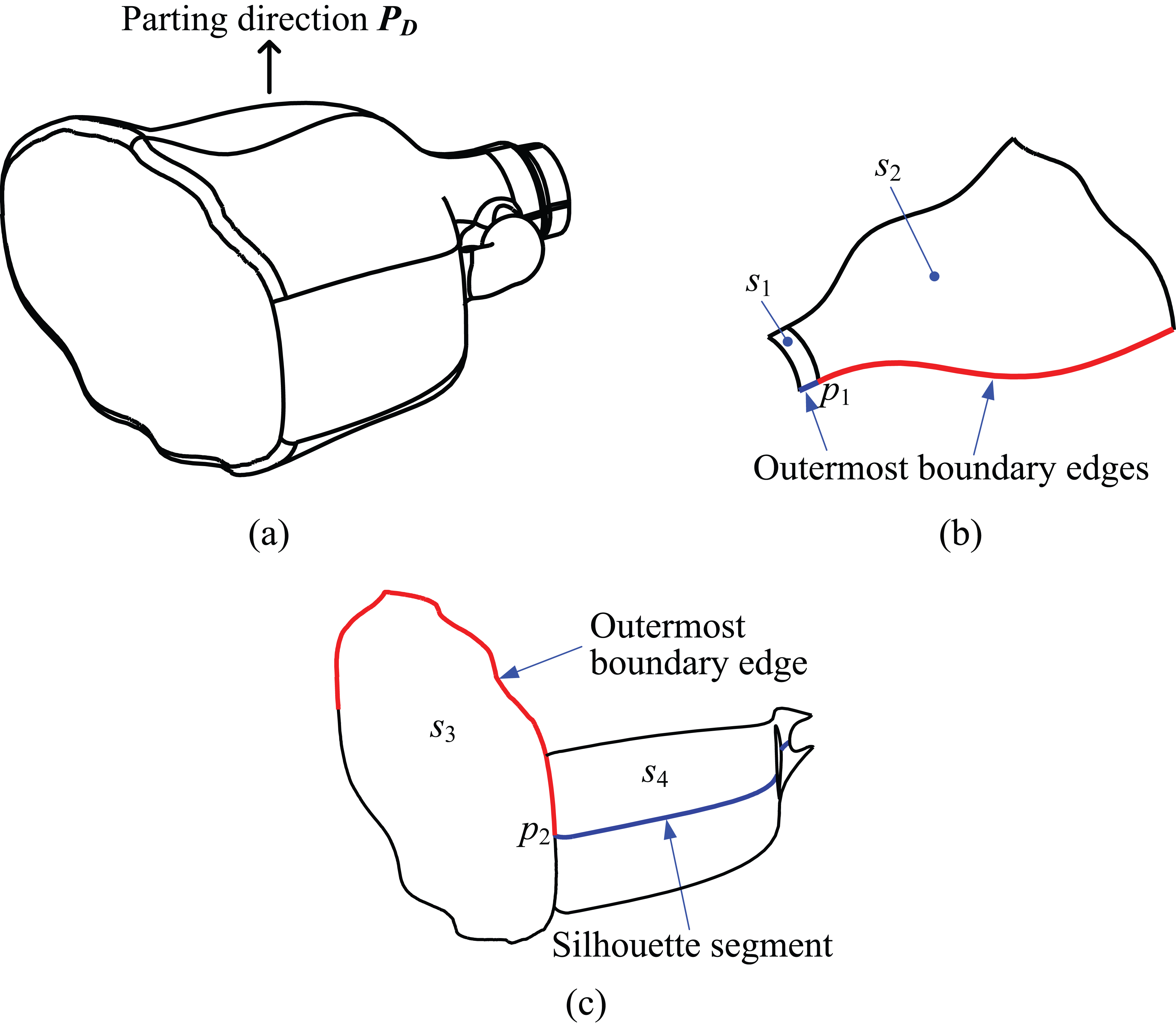
(a) Bottle model, (b) two outermost edges connected together, and (c) an outermost edge and a silhouette segment connected together.
However, there exist two special cases where adjacent outermost edges are completely decoupled. The first case is shown in Figure 21. In Figure 21(a), two silhouette segments and an outermost boundary a
1
a
2 of a vertical surface s
1 are decoupled. If these segments are connected by transitional straight lines p
1
a
1 and p
2
a
2, the resultant parting curves and parting surfaces are not smooth, having great abrupt changes in their shape. The following process is employed to replace the outermost boundary a
1
a
2 of surface s
1 with a more fitting one: let c be a straight line that connects two end points p
1 and p
2 of two silhouette segments. Two lines denoted by d
1 and d
2 are built from p
1 and p
2 and are perpendicular to both c and parting direction
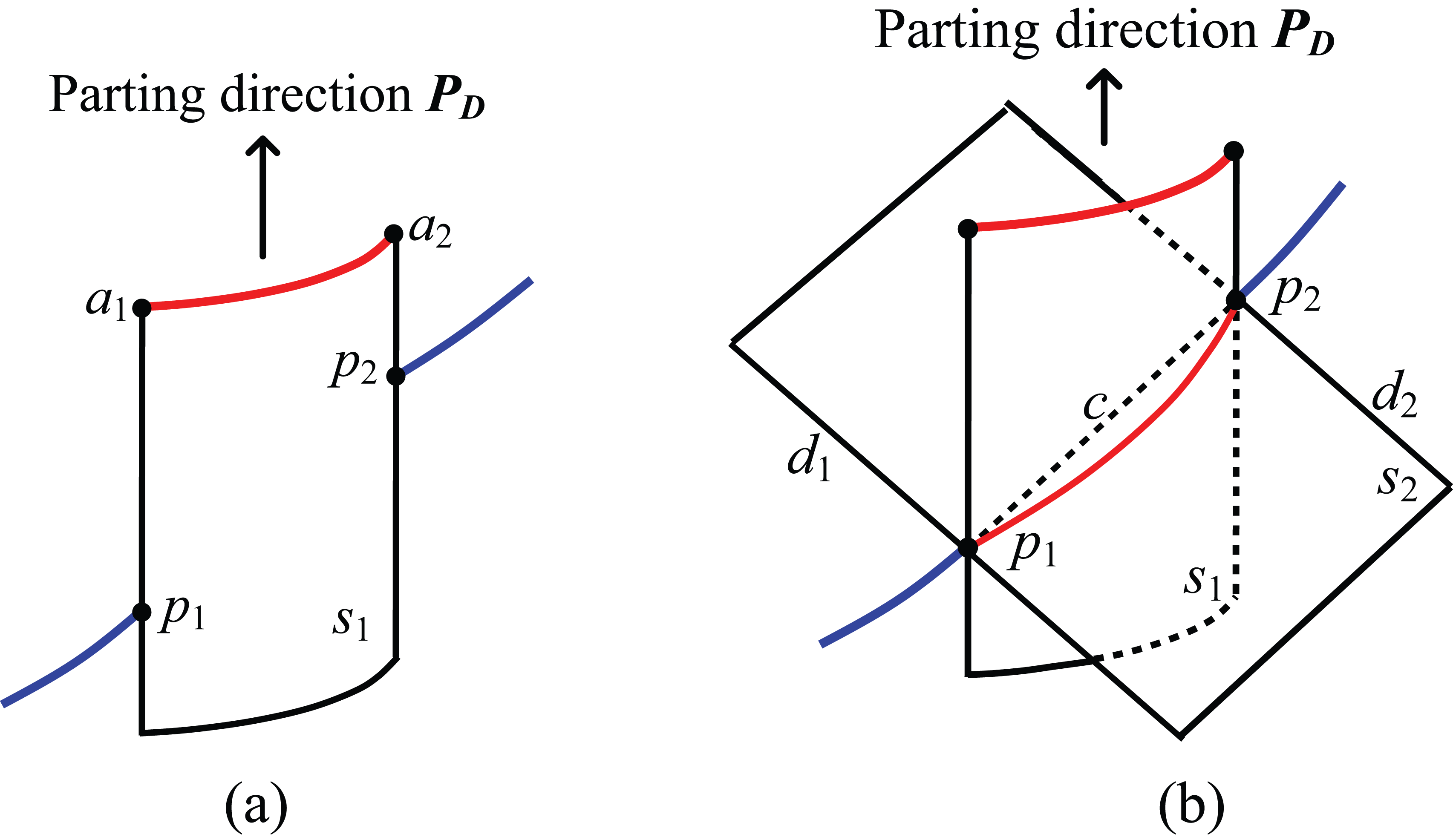
(a) Decoupled segments from vertical surface and (b) replacing outermost edge of a vertical surface.
Figure 22(a) shows another case involving decoupled segments of a free-form surface. In the proposed algorithm, the surface is considered to be a surface of undercuts and thus it is re-classified into the MSC set. All boundary curves of this surface form a closed loop that is automatically connected with the outermost segments of other surfaces to generate a parting curve (Figure 22(b)).
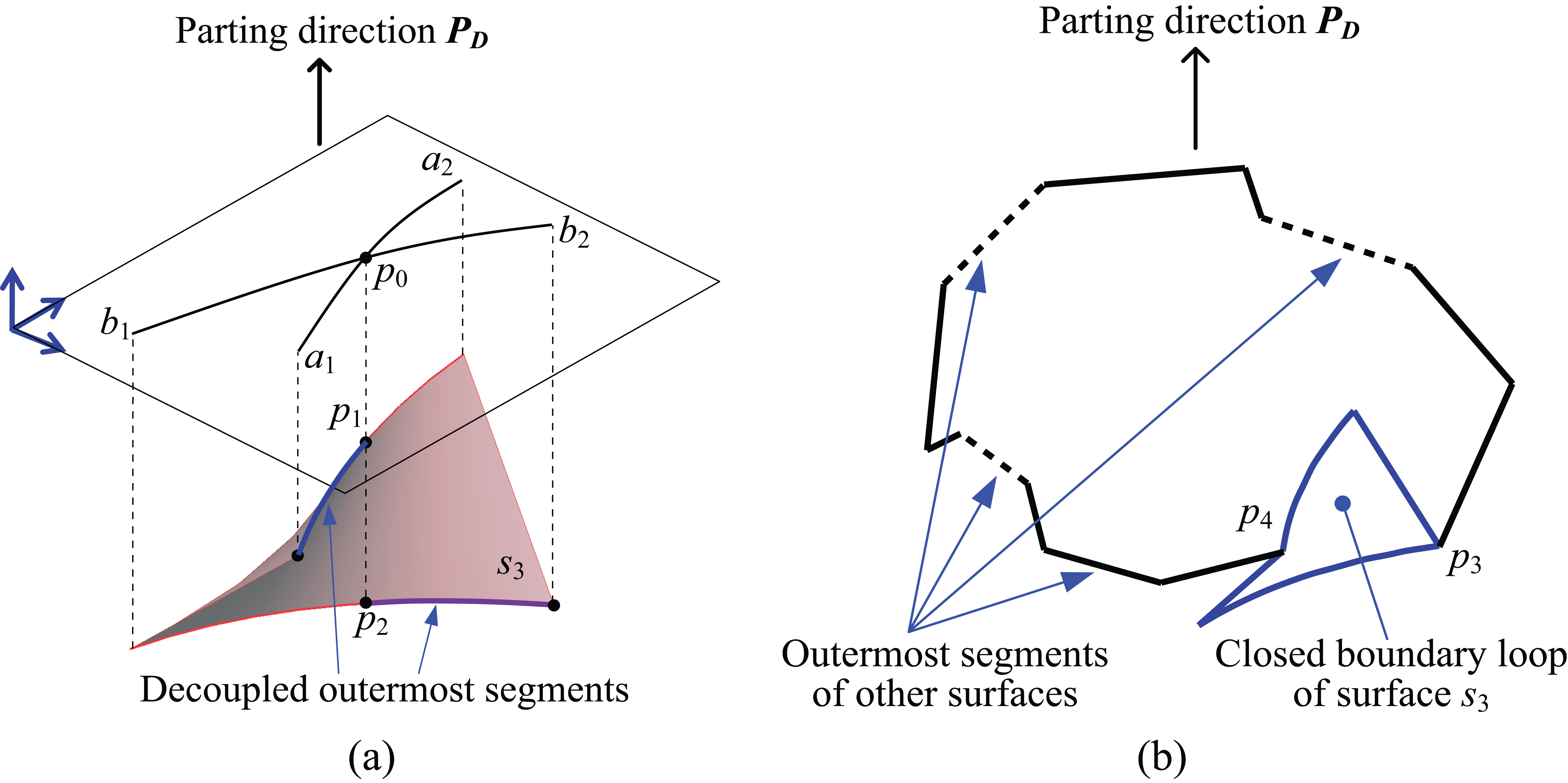
(a) Decoupled outermost segments of silhouettes and (b) closed boundary loop of surface s 3.
System implementation
The proposed algorithm has been implemented using the API-based Pro/Toolkit of Pro/Engineer Wildfire 5.0. Information about the geometric entities of the model (vertices, edges, and surfaces) is extracted and used as input for the algorithm. All equations describing edges and surfaces are formed based on this information. The resultant parting curve is also compared with that found by the Silhouette function of Pro/Engineer.
The first example implemented in this research was of a bottle, shown in Figure 23(a), which has been previously mentioned in several of the above sections. The proposed system analyzed all surfaces of the bottle to identify the different moldable surface sets (Figure 23(b)). Figure 23(c) shows the entire dual moldable surfaces of the model. The corresponding silhouettes of these surfaces were then determined (Figure 23(d)). The final parting curve generated by connecting the outermost boundaries of the relevant surfaces and silhouette segments is shown in Figure 23(e). As seen in the figure, the only inner loop is formed by connecting several silhouette segments. The generated parting curve can be used directly to obtain parting surfaces for future mold design.
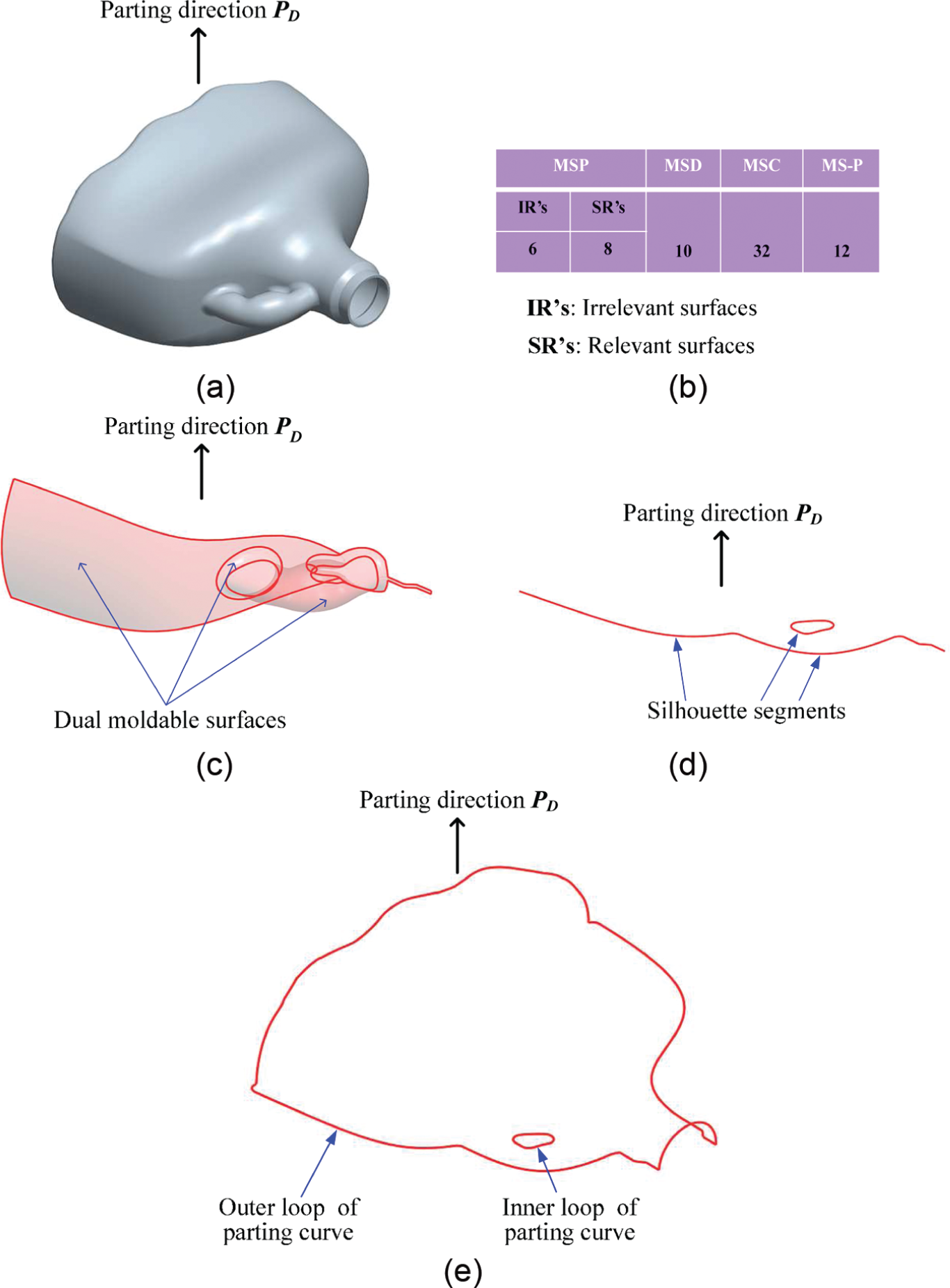
First example of implementation: (a) 3D CAD model, (b) list of different surface sets, (c) dual moldable surfaces, (d) silhouette segments, and (e) final parting curve.
The second example of implementation, a complex model illustrated in Figure 24(a), is the engine block taken from http://www.mcadcentral.com/proe/files/gallery.asp. All surfaces of the model were categorized into different groups through similar analysis. As shown in Figure 24(b), among the entire 422 surfaces, 162 surfaces were deemed moldable using
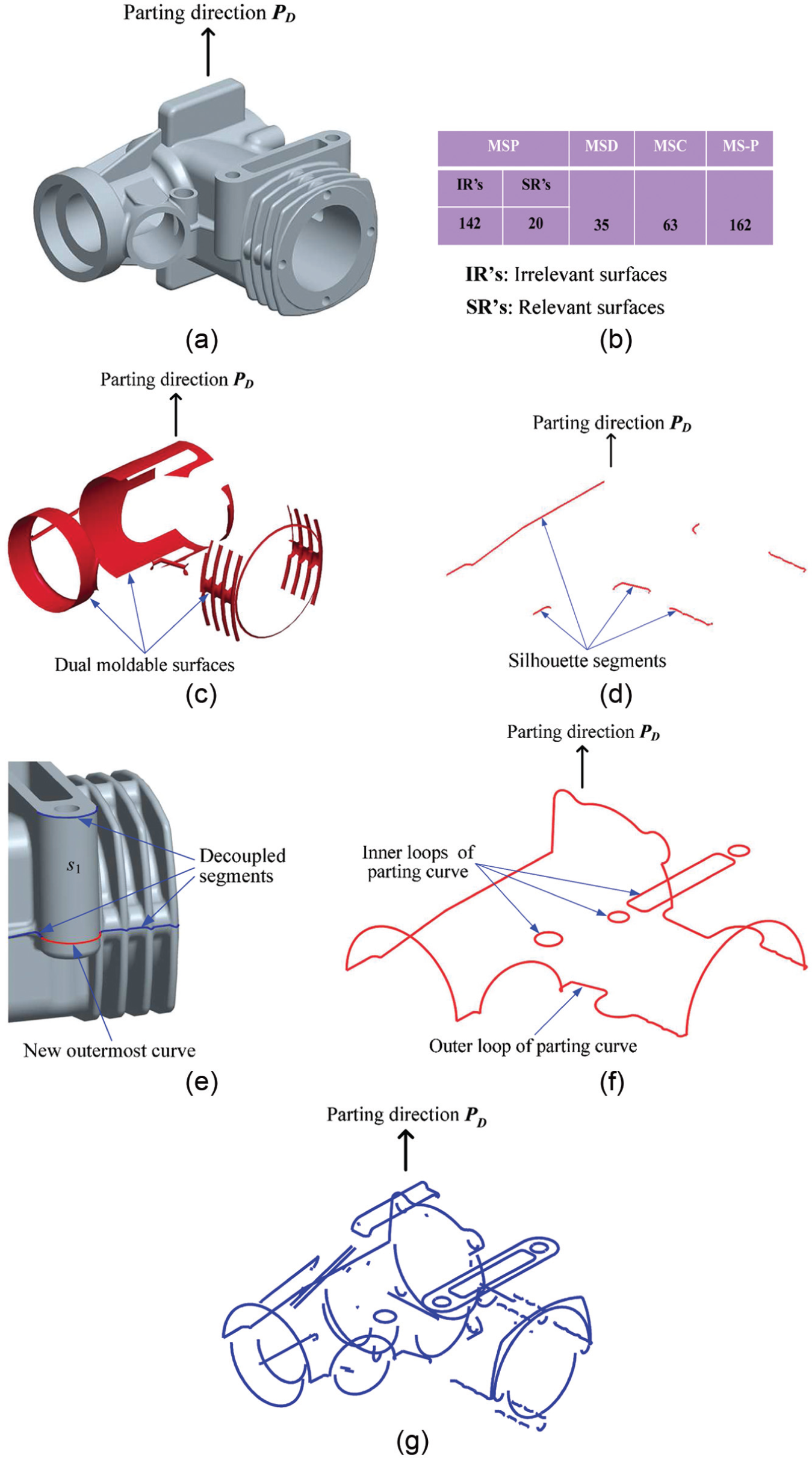
Second example of implementation: (a) 3D CAD model, (b) list of different surface sets, (c) dual moldable surfaces, (d) silhouette segments, (e) decoupled segments and new outermost curve, (f) final parting curve, and (g) silhouette segments generated by Pro/Engineer.
The parting curves have inner loops due to the existence of hole features as shown in Figure 24(a). Differing from the inner loop in the first example, these inner loops are basically the closed boundary curves of several relevant surfaces. The final parting curve is formed and demonstrated in Figure 24(f). In comparison with the silhouette curve generated by Pro/Engineer (as shown in Figure 24(g)), it is easy to realize that the parting curve generated by the system developed in this research is far superior. The parting curve can then be built upon to design the entire structure of the mold.
The proposed hybrid system is also capable of detecting internal channels of the model (piping or holes), even in the situation where these internal channels intersect the expected common parting line(s). The reason is that the proposed system is implemented based on the classification of moldable surfaces. Once surfaces are related to internal channels, they will be detected and classified into the MSC group (surface group of undercut features). In the proposed algorithm, the regions of these surfaces and their corresponding boundaries are then easily collected to form closed loops for further contributing to the side-core structures. Figure 25 shows the internal channels of the engine block and the projector cover that are recognized by the implemented system.
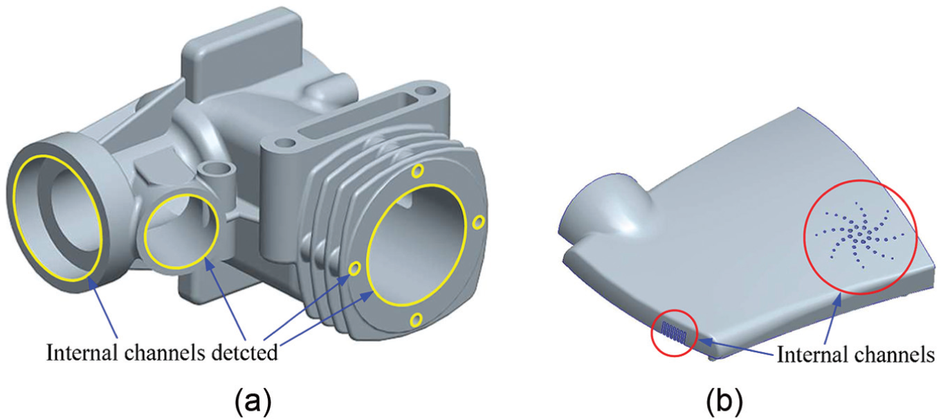
Recognition of internal channels of (a) engine block and (b) projector cover.
The third example of implementation is the bike-cushion model mentioned in Figure 1. All outer surfaces of the model are free-form surfaces. They have both visible and invisible properties due to the inconsistency of normal directions at different points. Thus, the resultant parting curves possess multiple-degree inclined properties and are generated only by silhouette segments. In the implementation, 25 outer surfaces are detected as relevant surfaces to the contribution of the parting curves (Figure 26(b)). These surfaces are classified into dual moldable surface (MSD) group and are used to extract their silhouette segments. Through the edge-projection technique and the ray test, the outermost and visible silhouette segments are determined. Based on this, the multiple-degree inclined parting curves are generated as shown in Figure 26(c). They are further used to create parting surfaces and split mold-pieces for further process of molding work.
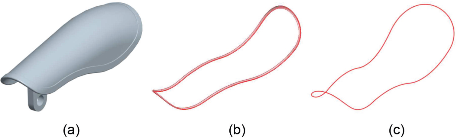
Third example of implementation: (a) bike-cushion model, (b) dual moldable surfaces and (c) multiple-degree inclined parting curve.
Conclusion
A hybrid approach that uses a combination of the surface-visibility algorithm and the silhouette-detection algorithm was proposed for the automatic generation of parting curves from free-form CAD models. Through the refining processes of removing irrelevant surfaces and unwanted silhouette segments, the proposed approach presents the following significant advantage—it can identify the loops of a parting curve faster and more accurately than existing algorithms and CAD systems. Using the free-form surfaces as the input for silhouette extraction, the proposed algorithms are robust and adaptable for use with various downstream CAD/CAM systems and applications currently used in industrial product/mold design and manufacturing.
Footnotes
Declaration of conflicting interests
The author(s) declared no potential conflicts of interest with respect to the research, authorship, and/or publication of this article.
Funding
The author(s) received no financial support for the research, authorship, and/or publication of this article.