
Abstract
Successful fuel filler tube hydroforming largely depends on proper loading paths, that is, application of internal pressure and axial feeding during the forming time duration. Generally, two part quality criteria are considered in selecting the feasible loading paths: (a) minimum part wall thinning and (b) part wrinkle free. Due to the highly nonlinear nature of the tube hydroforming process, iterative finite element analyses with adjustments based on forming experience are typically conducted to design the loading paths. In this research, genetic algorithm was integrated into the finite element analysis–based optimization, resulting in enhanced determination of the feasible loading paths. Genetic algorithm is a heuristic search based on mechanics of natural selection. A pair of pressure and axial feeding profiles was represented by connecting genes making up to be a chromosome. In each search, mutation and crossover operations generated a new generation of chromosomes. Fitness functions were formulated to assess performance of the chromosomes reflecting the part quality. Generations after generations, the optimal chromosomes are found only when the evaluated fitness function value falls within a user-defined tolerance. Unlike the typical iterative finite element analysis approach, it was shown that the iterative finite element analysis augmented with genetic algorithm was able to determine feasible pressure and axial feeding paths autonomously. The current approach still requires a lot of simulation runs, which must be offset by high-performance computing resources.
Introduction
Tube hydroforming (THF) process is an alternative sheet metal forming technique used to manufacture tubular parts with superior strength at lower production costs. The success of this forming process is highly dependent on key process parameters, that is, axial feed versus time and pressure versus time, the so-called loading paths. Since most hydroformed tubular parts are of complex geometry, both axial feed and pressure need to be precisely controlled to avoid excessive thinning due to excessive pressure and wrinkle due to excessive axial feeding. Developments of efficient and reliable methods of loading path determination have been carried out by many research groups.1–3 There are four main methods available.
The first method and probably the simplest one employs a set of analytical equations4,5 with assumptions to approximate the process parameter bounds, for example, minimum and maximum (or bursting) pressure for a simple bulge, calibrating pressure for corner fill, and axial feed displacement to prevent leakage. This method is somewhat limited to very simple tubular parts. The second method, the so-called “self-feeding technique,” 1 uses the process finite element analysis (FEA) to suggest necessarily minimum axial feed time history driven by internal pressure, linearly increased to bursting pressure, without any tube end constraints. The minimum axial feed profile obtained is then manually scaled up or modified to design a feasible axial feed profile through iterative FE simulations with correct boundary conditions. The scaling factors would be increased if the risk of part thinning is running high and reduced when wrinkles are observed. Unlike the first method, the self-feeding method is able to yield the loading paths. This method, however, is not suitable for parts with protruded features as they would burst too early, allowing only small amount of “self-fed” or drawn-in of material at the clamping area, not meaningful enough for further design iterations.
The third method is an adaptive FE simulation. 2 This method adaptively adjusts process parameters based on some feedback control techniques at each interval of simulation time steps during a single simulation run with an attempt to hydroform the part successfully without any defects. As a result, feasible loading paths are found within just one simulation run. The two key components of the method are performance index (e.g. bursting and wrinkle indicators) and adjustment logic (e.g. process parameter adjustment rules). Ray and Mac Donald 3 and Shu-hui et al. 6 developed a bursting indicator based on wall thickness and forming limit curve (FLC). They used strain difference, normal velocity, and a geometry-based consideration to develop a wrinkle indicator. Using fuzzy logic control, they established rules and membership functions for adjusting pressure and axial feeding of a T-branch shape. Generally, performance index, rules, and membership functions have to be formulated specifically for certain characteristics of each individual part. Improper performance index, rules, and membership functions will lead to bad solutions. This method still requires experience and careful investigation on formability of the part at hand prior to formulating the adaptive simulation method.
FEA method augmented with optimization techniques, as the last method, is probably the most rigorous and robust method to determine the loading paths. Both gradient-based methods 7 and non-gradient-based methods have been applied. For highly complex problems (optimizing a very large number of design variables), non-gradient-based methods are normally applied, such as response surface methods 8 and genetic algorithms (GAs). The main disadvantage of this method is that it requires a large number of simulation runs in order to achieve one optimal loading path.
A fuel filler neck as seen in Figure 1 is a gateway to deliver gasoline into the fuel tank. The fuel filler neck is designed to reduce the gasoline vapor escaping from an automobile fuel tank system. It is configured to receive fuel from a supply nozzle. The filler neck includes a one-piece funnel member having a tubular body and an elongated tubular member as seen in Figure 1. The funnel member is designed to be eccentric or non-axisymmetric, which has a relatively large inlet opening adapted for attachment to a receptor of the nozzle and a relatively small neck down outlet opening adapted for attachment to the inlet of an elongated tubular member. The elongated tubular member is connected to the fuel tank. Typically, the filler neck is formed by multiple tube expansion processes using solid punches. There is an on-going work attempting to replace the conventional forming process by tube hydroforming as it can potentially reduce the number of forming processes as well as increase the part strength.
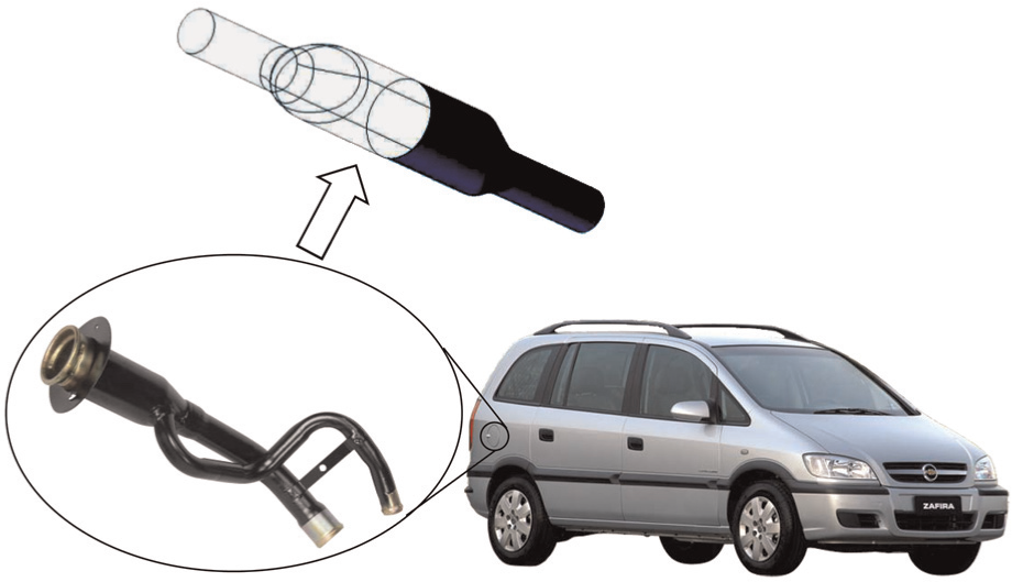
A fuel filler neck geometry (Courtesy: Honda website).
The fuel filler is a non-axisymmetric part with a large expansion ratio, and easily wrinkled. This makes the determination of optimal loading paths using the self-feeding method and adaptive simulation method more difficult as damaging wrinkles cannot be quantified precisely. In this article, FEA augmented with optimization technique has been applied to determine the optimal loading paths that can form the fuel filler part successfully. Optimization using GA in conjunction with dynamic explicit FEA was used to create new chromosomes (i.e. loading paths) that could provide a better solution by using crossover operation (interpolation between randomly selected loading paths) and mutation operation (extrapolation from the randomly selected loading path). Fitness functions that measure the performance of each new chromosome, were formulated based on part wall thickness and part dimensional accuracy.
FEA and setup
A number of researchers have applied FEA successfully on several THF processes: simple bulges, 9 T-shapes and Y-shapes,10,11 and automotive structural parts.11,12 Most of the FEA simulations were conducted by dynamic explicit FEA packages as they are suitable for problems with fast changing boundary conditions necessary to calculate the forming behavior with complex die surfaces and for handling large deformation forming. DYNAFORM and LS-DYNA were used in this work to simulate hydroforming of the fuel filler. To take advantage of part symmetry, a quarter finite element model was used to reduce computational time. The tube blank was meshed with 8600 quadrilateral elements. Belytchko–Tsay thin-shell element was assumed in the analysis.
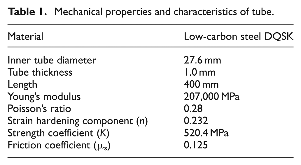
Barlat–Lian’s three-parameter model was used for the tube blank material model. Mechanical properties of low-carbon steel tubing grade DQSK used in this work are provided in Table 1. All of tool components were modeled with the rigid material model. A Coulomb friction coefficient of 0.12513,14 was used between the tube outer surface and the die surfaces. The fluid was not modeled but a uniformly distributed pressure was applied directly to tube inner surface. Time scaling of 1000 was used for reasonable computational time. Mass scaling was not applied here as it would likely lead to erroneous results, particularly when used in tube hydroforming analyses. Figure 2 shows the geometry setup used in this study.
Mechanical properties and characteristics of tube.
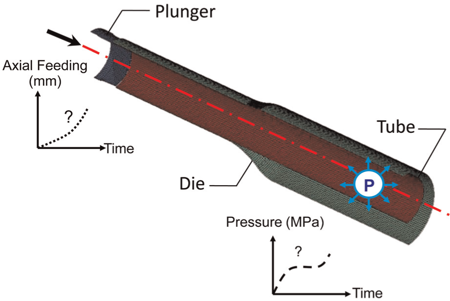
Problem statement and FEM setup.
Part quality criteria
Bursting criterion
Maximum part thinning criterion is a practical part quality index as it can be easily measured. This part thinning criterion was also adopted in this work to determine the risk of part bursting. FLC 6 can also be used for the same purpose. However, it was not applied here because it is expensive to determine such curve experimentally.
Wrinkle criterion
Plastic bifurcation theory and energy method2,15 are able to predict onset of wrinkle, but they cannot directly quantify the wrinkle. Instead, a rather simple geometry method, that can measure severity of the wrinkle, can be more useful. In the case of this fuel filler part, a small amount of wrinkles may even be helpful in preventing excessive thinning given that it can be “straightened out” afterwards. Therefore, a geometry method was utilized in this work. Figure 3 schematically shows initial tube blank and a fully formed part with wrinkles placed in the die. The wrinkle criterion (or near net shape criterion) is defined as the maximum radial distance of the tube toward its axial line, as shown in Figure 3.
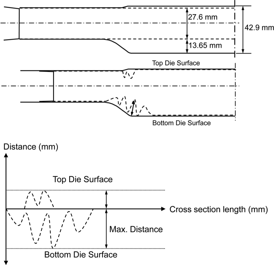
Wrinkle criterion (geometry base).
GA
GA, originally developed by Holland in the 1970s,16–18 is a stochastic search method based on evolution and genetics. The solution of an optimization problem with GA begins with a set of potential solutions or technically called chromosomes. A set of these chromosomes is called population. The chromosomes are evolved through several iterations called generations (or offspring). New generations are generated by crossover and mutation operations. A crossover operation generates two new chromosomes by interpolating from a pair of parent chromosomes. Only one out of the two new chromosomes is randomly chosen to exist in the next generation. The mutation operation would create new chromosomes by “mutating” or shifting selected chromosomes up or down in order to allow the search to be conducted outside the pool of initially selected chromosomes. After the new generation is set up, the process of FEA is carried out for each chromosome to predict the corresponding part thinning and wrinkle severity (material radial distance) as seen in Figure 3. Then, fitness functions are used to evaluate quality of the chromosomes in each generation. Chromosomes with higher fitness values are more likely to be selected as parents for the crossover operations. The strongest chromosome with the highest fitness value is referred to as elitist and kept intact into the next following generation. This process of fitness evaluation, selection, crossover, and mutation would be carried out until completing the population size of 16 chromosomes including the elitist, resulting in a new generation. This optimization algorithm will be stopped when the elitist chromosome stays the same up to 10 generations continuously; then the elitist is considered as the optimal loading path. However, if the number of iterations exceeds a predefined number (30 generation limit was defined in this work), the algorithm is forced to stop and the chromosome with the highest fitness is taken as the optimal solution for the problem. The GA used in this article is schematically shown in Figure 4.
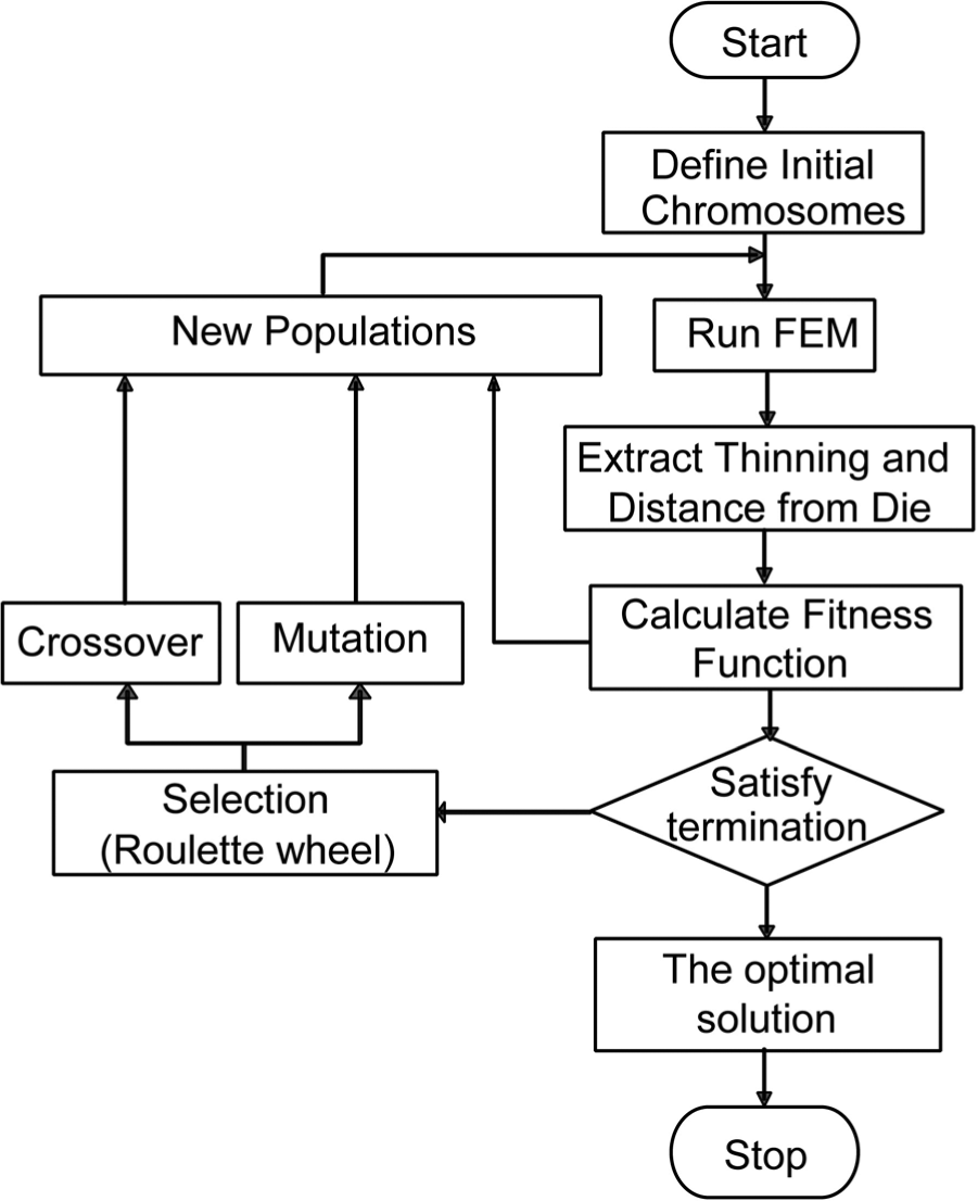
An overall flow chart of optimization algorithm.
Initial population
Four pre-determined profiles of pressure and axial feeding were calculated and each coded by 10 connecting genes (Figure 5) to generate an initial population of chromosomes. Typically, GA selects or modifies genes randomly to construct initial chromosomes. This may result in initial chromosomes or loading paths that cannot be achieved in real production. In this work, therefore, the initial pressure and axial feeding bounds were first approximated by pressure bursting calculation and self-feeding method. 1 Then simple linear and multiple-linear models were used to represent the loading paths, as this type of profile is normally achievable by most hydroforming systems. A total of 16 initial chromosomes were then established by connecting the genes of the 4 initial pressure profiles and 4 initial axial feeding profiles (Figure 6). It should be noted here that the number of genes was defined based loosely on the load path nonlinearity anticipated.
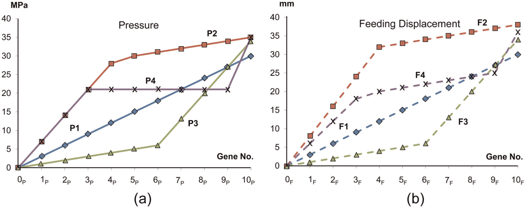
Initial loading paths for the optimization problem: (a) possible pressure profiles and (b) possible axial feeding profiles.
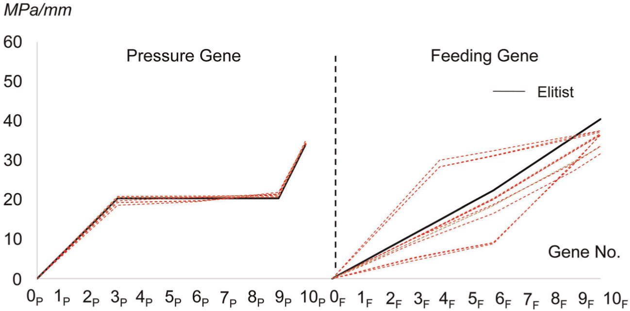
Loading paths of the 1st generation.
Fitness function
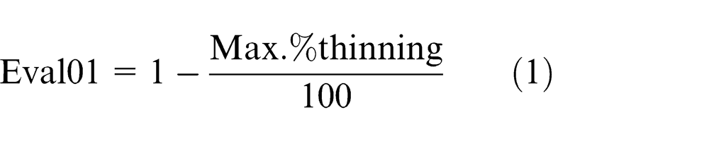
An evaluation function is used to evaluate the quality of chromosomes obtained from each generation. The chromosome receiving a high evaluation value will potentially be selected for inclusion to the next generation. To obtain the evaluation function, a fitness function has to be defined. Here, a fitness value of fuel filler part quality is defined by considering both bursting and wrinkle criteria. Both criteria should be normalized to a scale of 1. The corresponding thinning values are 0 % to 100 %. In the fuel filler part, the expansion zone has 42.9 mm of diameter. Based on results from many simulations, the wrinkle criterion is almost in the range of 0 to a quarter of the expansion zone diameter (42.9/4 = 10.725 mm). The Eval01 is defined by considering bursting criterion normalized as shown in equation (1). The small values of Eval01 suggest a high risk of burst, while large values suggest low risk of bursting (good quality)
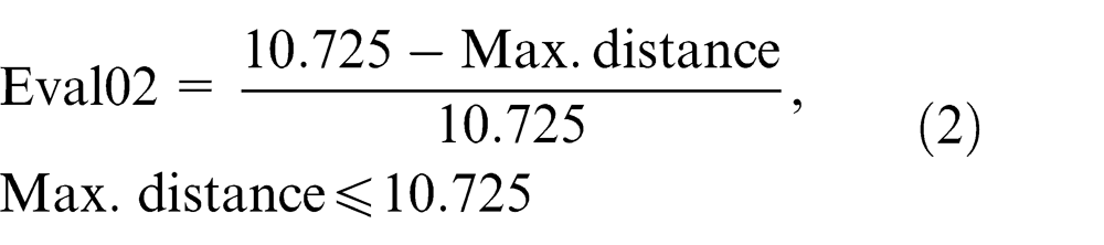
The Eval02 is established as a part dimensional accuracy (or near net shape) indicator expressed by equations (2) and (3). Small values of Eval02 suggest that large wrinkles have occurred, while the value of 1 suggests that the part has been formed against the die surface completely without any wrinkles (good quality)
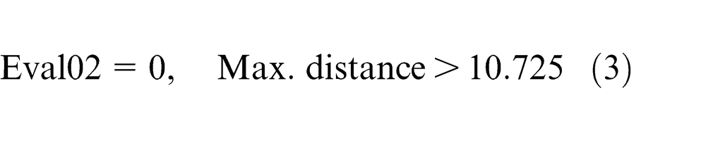
To evaluate each chromosome performance in hydroforming of the fuel filler part for both part thickness and dimensional accuracy, the fitness function is expressed as below
The strong chromosomes are those that have high fitness values. Therefore, the objective function in this optimization problem is maximizing the fitness function.
Genetic operations
Selection method.
The selection method leads the genetic search toward encouraging regions in the search space. Many selection methods 18 have been compared and examined. Common types of them are the roulette wheel selection, steady-state reproduction, μ+λ selection, ranking, and scaling and sharing.
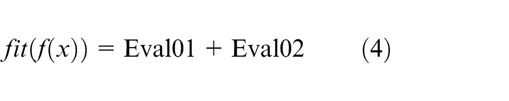
“Roulette Wheel Selection” structure is used in this study, as it tends to select stronger chromosomes allowing them to prevail. This selection method uses probability based on each individual fitness, expressed by equation (5)16,18
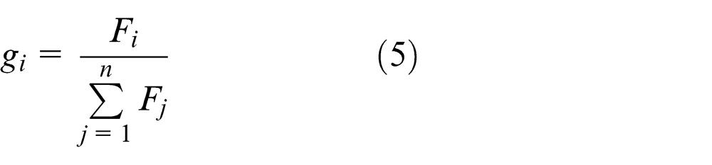
where gi is the probability of individual i (chromosome), Fi and Fj are the fitness function values of individuals i and j (generation), respectively, and n is the size of population.
Crossover.
Crossover operator creates new chromosomes that may be stronger than their parents. Two chromosomes are randomly selected from the population for mating. Two new chromosomes, called offspring, can be obtained by exchanging or modifying some genes of the selected chromosomes. The arithmetic crossover equations are shown in equations (6) 18 and (7) 18
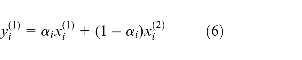
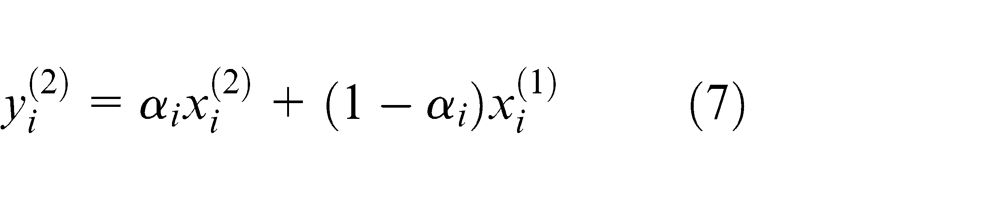
where xi(1) is the first parent, xi(2) is the second parent, yi(1) is the first offspring, yi(2) is the second offspring, and α is set to 0.1. From equations (6) and (7), each gene of the first and second parents is operated on by interpolation. The value in each offspring gene will be changed more or less depending on α (the weight factor). The “α” factor of 0.1 causes the offspring to gradually change from its parent’s profiles, while α of 0.5 causes the offspring to rapidly evolve, in this case, to be the average of the parent’s profiles. Only one of two offspring is selected to be used in the next generation. This operation is performed 12 times to generate 12 chromosomes for a population of 16 chromosomes.
Mutation.
Mutation operator creates an offspring by applying a random change to an individual chromosome in the current generation. The mutation operator plays an important role for the search ability of the algorithm as it can prevent the premature convergence of a new generation. Typical mutation operators used in GA include uniform mutation, boundary mutation, and non-uniform mutation. The following non-uniform mutation operator is used
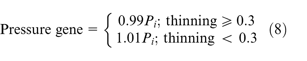
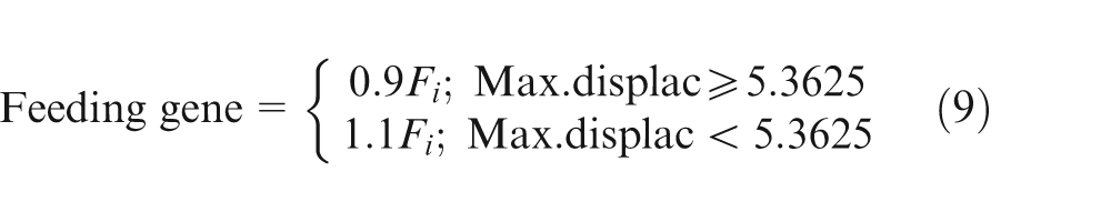
The mutation equations (equations (8) and (9)) were developed to shift the profiles of pressure and feeding up or down. This is aimed to adjust the magnitude of pressure and feeding out of range from the initial profiles. The allowable thinning of material in bi-axial tensile mode is usually set to be 30% used in equation (8). The pressure will be reduced by 1% from the selected chromosome that results in the thinning equal or higher than 30%, or otherwise the pressure is increased by 1%. The feeding will be reduced by 10% from the selected chromosome that results in wrinkles of maximum distance equal or larger than 5.3625 (half of maximum observed wrinkle distance of 10.725; see fitness function), or otherwise the axial feeding will be increased by 10% as shown in equation (9). Three chromosomes are created by the mutation operation for the new generation.
Optimization results and discussion
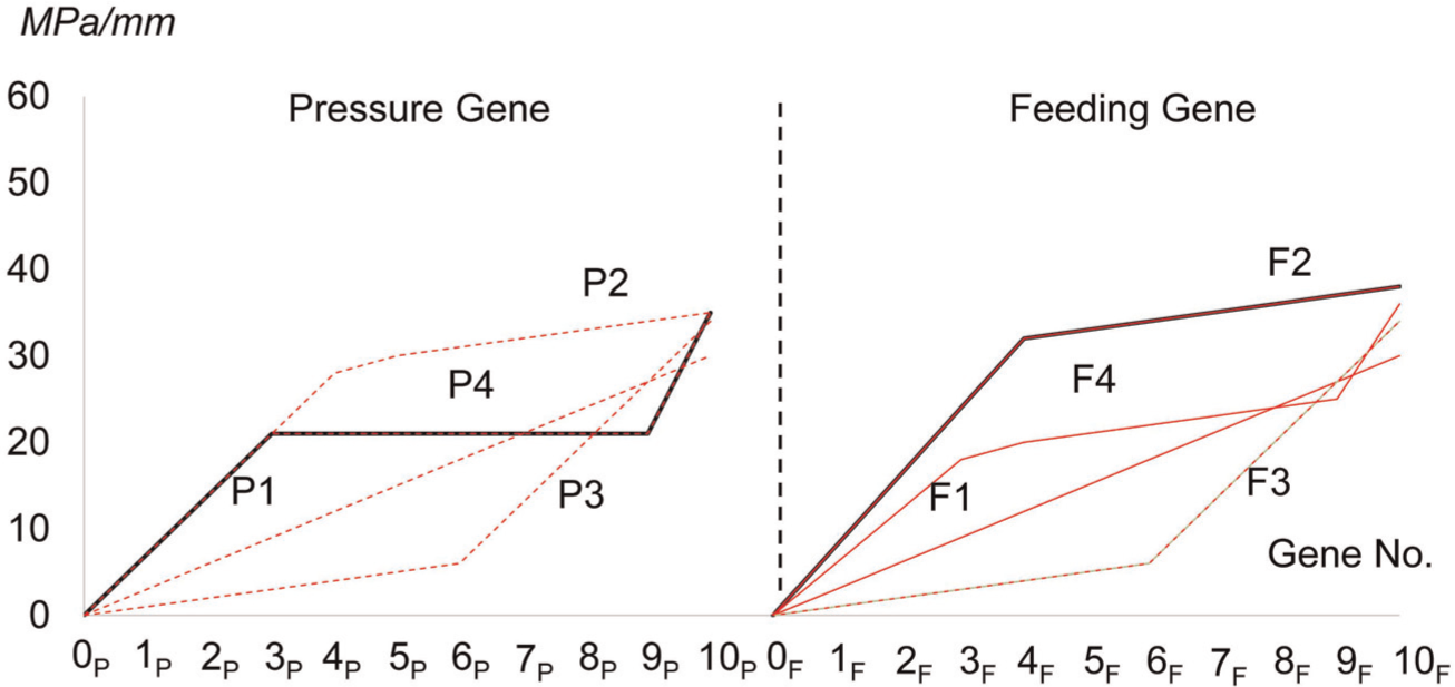
After fitness evaluation of all the initial chromosomes from the first generation (Figure 6), it was found that the elitist chromosome (P4, F2) yielded the highest fitness value of 1.46, which is comprised of Eval01 of 0.533 (46.69 of thinning—bursting) and Eval02 of 0.93 (0.75 mm of max. distance—small wrinkle). After five generations, the pressure profiles seem to be converging to the initial P4 pressure profile, while there are still variations in axial feed profiles (Figure 7). Compared to the 1st generation, the elitist in the 5th generation gave a higher fitness value of 1.55, which is comprised of Eval01 of 0.607 (39.25 of thinning—still bursting but with a lower risk) and Eval02 of 0.942 (0.62 mm of Max. distance—smaller wrinkle).The algorithm was stopped at the 28th generation by the fact that the same elitist existed for over 10 consecutive generations. This elitist was then considered as the optimal solution, that is, “optimal” loading paths for hydroforming of the fuel filler part (Figure 8). The optimal pressure profile resembles P4, where it gradually increases up to 20 MPa, remains constant, and rapidly shoots up to 33 MPa at the end. The corresponding axial feed profile is found to be linearly increasing up to 54 mm as shown in Figure 8. Based on the FE simulation result, these loading paths could successfully form the part with good quality of 16.31% thinning and insignificantly small wrinkles (0.75 mm Max. distance). Figure 9 shows thinning distributions of the simulated part. No visual defects were found. The optimization history is shown in Figure 10. It can be observed that the fitness values of the chromosomes were low and scattered in the early generations, and later converged to higher values (1.76) with much smaller variations, where the optimal was found.
Loading paths of the 5th generation.
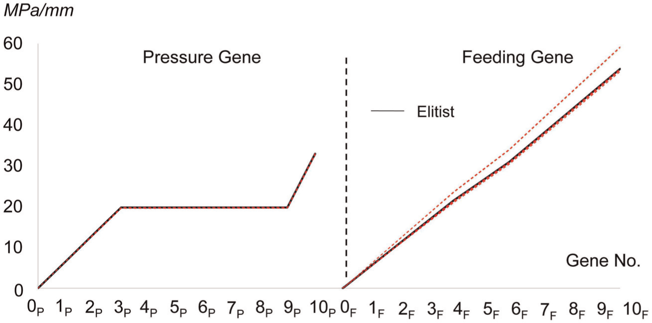
Loading paths of the 28th generation.
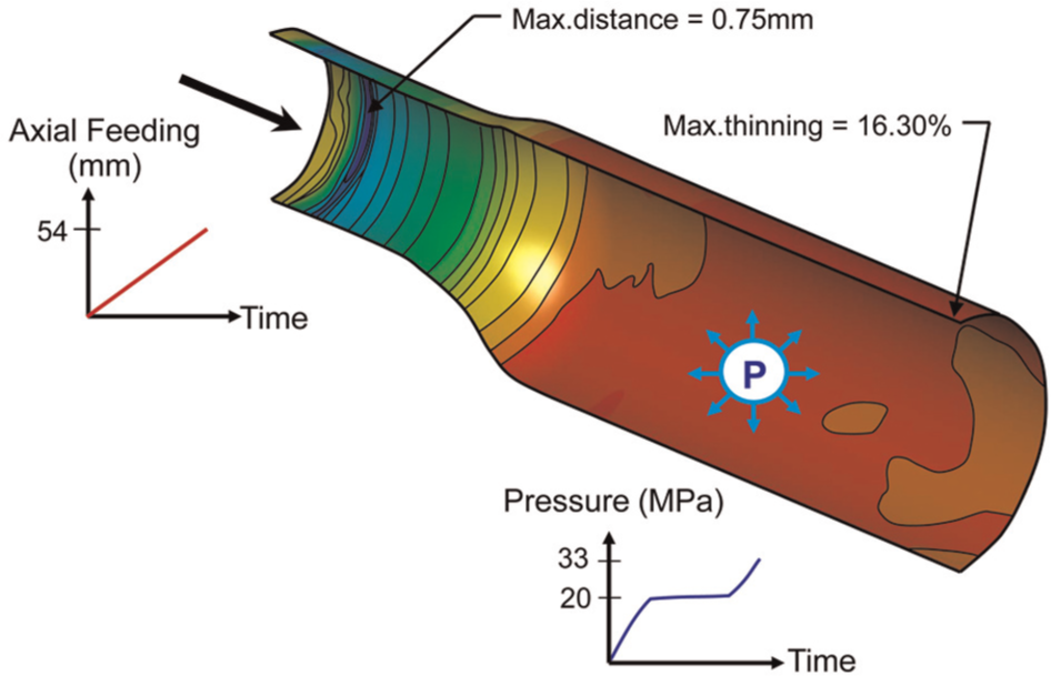
Thinning distributions on the deformed part from the feasible loading paths.
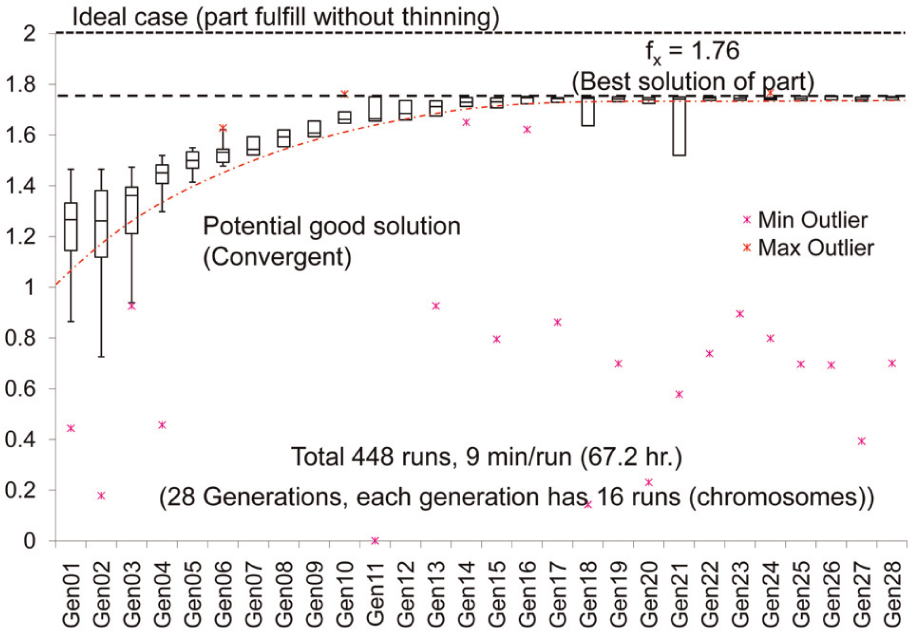
The evolution process of objective function.
Conclusion
GA was integrated into FE-based optimization method to determine feasible pressure and axial feeding paths (i.e. loading paths) for hydroforming of a non-axisymmetric low-carbon steel fuel filler part. Based on some preliminary analyses and practical considerations, 4 pressure profiles and 4 axial feeding profiles were designed to generate the 1st generation of 16 initial chromosomes (or loading paths) for the GA. Roulette wheel selection, crossover operator, and mutation operator were designed and implemented to create new generations in search for the “optimal” loading paths. Part thinning and wrinkle severity were used to formulate the fitness function, which was to be maximized in this optimization problem. It was found that the implemented algorithm converged to the optimal solution within 28 generations (28 × 16 simulation runs). Based on the FE simulation result, the “optimal” loading paths could successfully hydroform the part with good quality of 16% part thinning and wrinkle free. This FE-based optimization with GA proved to be capable of autonomous determination of feasible loading paths for hydroforming this non-axisymmetric part. These feasible loading paths can potentially reduce a lot of time and costs spent during process tryouts. Forming experiments have been planned to validate these loading paths. The current optimization approach still needs a lot of simulation runs. Therefore, high-performance computing resources are required.
Footnotes
Acknowledgements
The authors would like to thank the National Metal and Materials Technology of Thailand for permission to use DYNAFORM and the tube hydroforming system for this research work.
Funding
This research received no specific grant from any funding agency in the public, commercial, or not-for-profit sectors.
Declaration of conflicting interests
The authors declare that there is no conflict of interest.