
Abstract
Due to the increasing demand for small, complex parts, researchers are putting a great deal of effort into applying the metal forming process to the micro and meso world. However, the tube hydroforming process is yet to be fully realized on this small scale because of the difficulties which arise in scaling the conventional tooling to the microscale. This article discusses the difficulties that arise as a result of simply shrinking the traditional hydroforming tools to the microscale. A simple mathematical model is then proposed as a way to help designers determine the limits of the conventional punch with a tapered nose commonly used in tube hydroforming. The model is then validated by performing a finite element analysis of the punch, and the results of the model are discussed in relation to the scaling concepts posed at the beginning of this article. It is determined that as the punch shrinks down, the stresses on the punch rise significantly as a result of changing aspect ratios of the workpiece and the inability to accurately machine very small holes through the punch body. A nonconventional tube hydroforming method may therefore be required to perform micro-tube hydroforming operations, especially on harder materials.
Introduction
The rapid reduction in the size of consumer electronics and medical devices has created a demand for increasing number of small and complex components. This has made the metal forming process an attractive subject for many micro-manufacturing researchers due to its ability to mass produce complex near net-shaped parts. Although many metal forming techniques have already been successfully scaled down to the micro level, the tube hydroforming (THF) process is yet to be fully realized on the microscale. The THF process is capable of creating complex tubular shapes using high-pressure fluid in the place of a hard tool to plastically deform a tubular blank into a desired shape. In order for shapes of increased complexity to be created, axial feed must be provided to the tube as the deformation process takes place.
Tube hydroformed parts are typically used in the automotive and aerospace industries due to their high strength-to-weight ratios and complex shapes, but they can also be found in applications from bicycle frames to household faucets. If the process could be effectively scaled down to the microscale/mesoscale, a whole new set of industries could make use of the advantages of THF. For example, as the medical industry moves toward less invasive surgeries and procedures, smaller and smaller parts will be needed for the sensors and robotic devices that are becoming increasingly common in the operating room. THF could be used to efficiently fabricate sensor housings and tools that can stand up to the rigorous sanitation procedures required of surgical tools and implants to be used inside the human body. Tube hydroformed parts would also be useful in the microelectromechanical systems (MEMS) industry as micro-shafts and gears. The excellent thermal and electrical properties of the metallic materials that THF is capable of shaping also make the process quite attractive for use in rapidly shrinking consumer electronics. Additionally, complex metallic micro-tubular parts may also be useful in the development of micro fluidic and micro heat exchanger devices for similar reasons.
Currently, there are two proposed methods for producing micro-tube hydroformed parts, although the majority of the studies done using these methods are limited to bulging studies. The first method is to simply scale down the macroscale tooling to the microscale. In 2012, researchers at the University of Strathclyde developed a micro-THF press (Figure 1) based on the principles of macro-THF machines. 1 The researchers carried out studies dealing with the formability of the workpiece material and deflections of the die 2 and even managed to create a fully formed stainless steel “camera shaft.” However, the camera shaft which was formed did not require the application of axial feed. The researchers suggested that the traditionally used hollow tapered punch could be applied to the micro world but did not report any findings gained from studies with this punch.
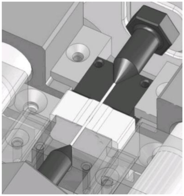
Micro-tube hydroforming device based on scaled down conventional hydroforming tooling. 1
The second micro-THF method was proposed by Ngaile and Lowrie3,4 in 2014 and took a fundamentally different approach to hydroforming on the microscale. This method was based on a floating die assembly, in which all of the punches, dies, and feeding systems are submerged into the high-pressure working fluid. Instead of using a tapered punch to confine the high pressure fluid to the inside of the tube, the floating die makes use of a seal placed between the dies and workpiece to keep the pressure in the die cavity low while all other areas are exposed to the high pressure fluid. This produces the same pressure differential between the inside of the tube and the die cavity without the requirement that the punch seal the ends of the tube. This tooling has been shown to be able to perform both the material feeding requirements and the expansion requirements of THF. A conceptual drawing of the floating die micro-THF system is given in Figure 2.
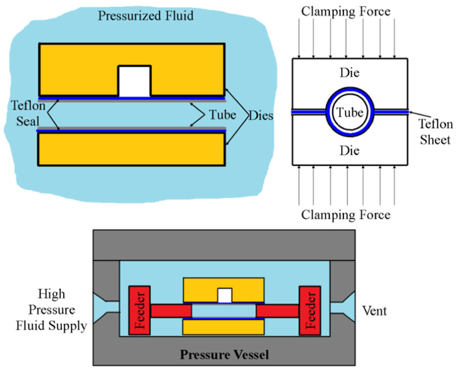
Conceptual drawings of the floating die micro-tube hydroforming system.
Objectives and research approach
In order to speed the commercialization and adoption of the THF process on the micro- and mesoscale, a set of design guidelines must be developed to assist the designer in choosing the correct hydroforming strategy. Therefore, the major objectives of this study are to identify the variables which will affect the scalability of the THF process, determine where potential problems may arise, and establish guidelines for when it is economical to scale down the conventional tooling and when it is necessary to use a nontraditional method.
This article is divided into three sections. Section “Conventional THF system and micro/meso scaling limitations” presents an overview of the conventional THF tooling and the difficulties in scaling this tooling to the microscale/mesoscale. Section “Analytical model for determination of maximum induced stresses of the punch” covers an analytical model which is proposed to help designers quickly determine the stress that they are likely to see in the tapered punch for a particular geometry and feeding force. Section “Finite element simulations of the micro/meso-THF process and model validation” discuses finite element simulations that were carried out to determine process forces and pressures which are used in the analytical model, as well as finite element simulations that were carried out to validate the analytical model. Additionally, section “Finite element simulations of the micro/meso-THF process and model validation” proposes some design guidelines that can be used to determine which method of THF should be used.
Conventional THF system and micro/meso scaling limitations
The THF process uses high-pressure fluid in place of a hard tool to carry out the plastic deformation of the tubular workpiece into the desired shape. The proper application of axial stress and internal pressure on the tube can create parts with tailored thickness distributions, complex cross sections, and increased strength. Additionally, the THF process can be used to reduce the number of secondary operations such as joining and hole making because holes can be made with the hydropiercing, and two tubes can be joined by allowing them to form together as the process is carried out. 5 These benefits come at the cost of long cycle times and a high tooling and equipment costs. 6
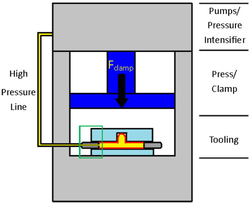
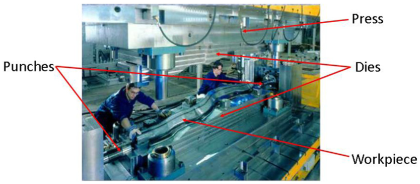
The conventional THF tooling consists of several main parts, as shown in Figure 3. These parts include the tooling (i.e. the dies and punches), the tubular workpiece, the pumps used to generate the high-pressure medium, the press used to clamp the die halves, and the actuators used to feed the tube into the die cavity. 7 The dies used in THF are generally segmented into two pieces so that the part can be removed after it is formed. The traditionally used punch has a tapered nose which is used to simultaneously provide axial feeding and seal the tube ends via plastic deformation of the workpiece, as shown in Figure 4. The pumps used to pressurize the inside of the tubes generally use water as the working fluid, but may also use gases or oils for hot and warm forging, respectively. The presses used to clamp the die halves are generally hydraulic presses, which are well suited to the high loads and low cycle times encountered in a THF process. A typical THF setup is shown in Figure 5.
Main THF systems.
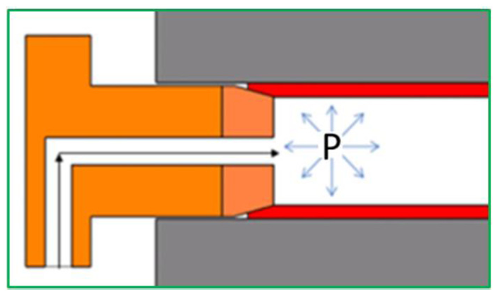
The tapered punch simultaneously sealing and feeding the tube ends.
Typical tube hydroforming equipment setup (Schuler hydroforming).
The conventional THF process can be divided into five steps, as indicated in Figure 6. Four steps are common to all conventional THF operations. The first step is to place the specimen into the die cavity and clamp the two die halves together with the press. The second step is to bring the punches into position so that a seal is created on the tube ends and to fill the tube with fluid to bleed out the air in the system. The third step is to form the part by increasing the internal pressure in the tube and pushing the tube ends toward the die cavity using the punches. Finally, the fourth step is to pull back the punches, open the dies, and eject the hydroformed part. In some cases, additional preprocessing steps, such as bending, are required to ensure that the workpiece fits into the dies at the start of the hydroforming process.
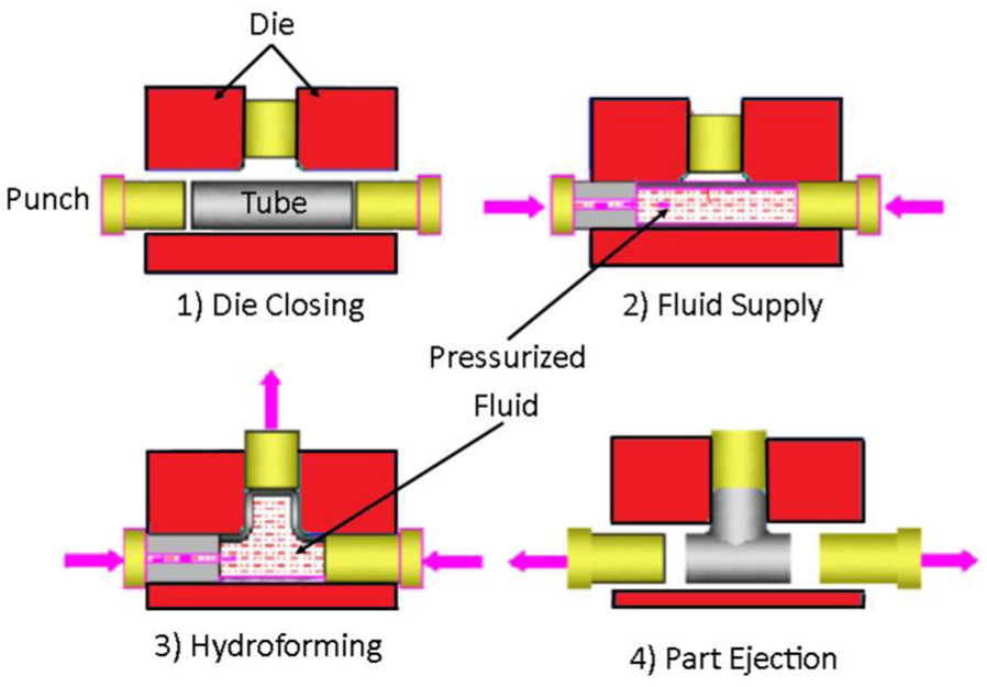
The four steps in a typical tube hydroforming operation.
As stated previously, increasing demand to create micro-sized parts has put pressure on industries to scale down their processes to meet the demand for small parts. This is no different for the THF industry, but due to several factors, this miniaturization is yet to be realized on the practical scale. It is imperative that the potential road blocks to scaling down the THF process be identified and strategies be developed to overcome them. To this end, the following sections will examine the scalability of the pumps/pressure intensifiers, clamping press, and the tooling used in the THF process.
Scalability of pressure intensifier system and clamping system
The purpose of the pressure intensifiers is to create the pressure that is used to expand the tube. By applying the geometric scaling laws, one can see that scaling the geometry of the system by a factor λ has no effect on the pressure required to expand the tube. This can be explained by examining a simplified case where the stress in the tube is given by the hoop stress. The hoop stress in the tube before scaling is defined as
The purpose of the clamping press is to hold the die halves together during the hydroforming process. In general, the press capacity is chosen such that the dies can be held together even if the entire projected area of the final part was subjected to the maximum pressure of the working fluid. Using the geometric scaling laws, it is clear that a process that is scaled by a factor λ will have its projected area scaled by a factor of λ2. Recalling that the pressure needed to expand the tube is unaffected by the scaling factor, one can see that the required press capacity is reduced by λ2. Thus, a press with greatly reduced capacity, and cost, can be used to perform a micro-THF process.
It is also important to consider cycle time needed to operate the process in a cost-effective manner. In order to reduce cycle times, the designers of macroscale THF presses have turned to using two sets of hydraulic rams: one set to rapidly position the dies and another to apply the full clamping pressure. The pressurization system has also been revised to reduce the time it takes to initially fill the tube by adding a high flow rate pump to rapidly move the working fluid into the tube and remove the air to the system. 8 On the microscale, much less costly solutions to the cycle time problem can be achieved. Due to the small size of the tooling, it is possible to utilize die sets on rotation, rapidly switching between previously prepared die set and die set which is currently in the press, so that operations such as die lubrication, positioning of tubes and tools, and part ejection can be done outside of the press. This would have the effect of reducing the time that the hydroforming machines sit idle, waiting for the secondary operations to be completed. The small size of the process may also provide the opportunity to prefill the tubes because capillary action will tend to hold the working fluid inside the tube. There are numerous other strategies which can take advantage of the small size of the tools and workpieces to decrease cycle time and improve the profitability of the THF process.
Furthermore, because the pressure intensifiers and clamping press do not operate directly on the tube, their size is of little importance to the feasibility of the THF operation. In fact, currently available pressure intensifiers and small hydraulic or mechanical clamps will likely be useable in the micro-THF process. In short, the process scalability is not affected by the presses or pumps, due to the external nature of the devices.
Scalability of THF workpiece
The behavior of the workpiece dictates the achievable final shape of the part and the loading paths needed to obtain the desired deformation. This information is readily available or relatively easy to determine on the macroscale. For example, the hydraulic bulge test can be used to quickly determine the flow stress of the tubular workpiece 9 or the frictional condition in the expansion zone could be calculated using a pear-shaped hydroforming tribotest.10,11 On the microscale, however, this information is much more difficult to attain. This is due to changes in the material behavior and interactions between the workpiece and hydroforming tools known as size effects, which are defined as the changes in a process which cannot be explained by simple scaling laws.
Many groups of researchers have carried out experiments on microscale process which have helped to create an improved understanding of the various size effects. For example, Krishnan et al. 12 performed a series of forward extrusions on CuZn30 with both fine and coarse grain sizes and showed that when the grains were large, the strains along the workpiece length were nonuniform, and that these large grains caused a curvature in the product. Chan et al. 13 have also carried out a series of experiments examining the micro-extrusion using copper billets and showed that the friction in the process was increased, and that when the grain size was large compared to the feature size, the individual orientations of the grains had a marked effect on the final shape of the part and the extrusion load. Studies of the cylinder upsetting experiments carried out by Guo et al. showed a decrease in the flow strength of the specimen as the process was scaled down. Furthermore, an increase in interface friction as the part size was reduced was also observed in cylinder upsetting, but it was noted that there was no change in the friction when there was no lubrication used. 14 The lack of a size effect in the dry condition is in good agreement with a proposed frictional model based on open and closed lubrication pockets summarized by Engel. 15 Kals and Eckstein 16 observed a decrease in the flow stress, vertical anisotropy, and ductility as the number of surface grains increased relative to the number of interior grains in their experiments into the micro-sheet metal forming process. Many of these same effects were observed in experiments on aluminum sheet performed by Raulea et al., 17 who also noted a loss in the repeatability of the final part shape. Klein et al. 18 discovered that the ultimate tensile strength of copper and aluminum foils also decreased as they were scaled down and the size of the grains approached the thickness of the foil. The decrease in the flow stress as the grain size-to-sheet thickness ratio increased was also observed by Mahabunphachai and Koç 19 in stainless steel sheet. Diehl et al. 20 reported that the spring-back behavior of thin metal foils is dependent on both material and scaling factor in their bending study of copper and aluminum sheets. In their investigations of the micro blanking and deep drawing process, Fu et al. noted a decrease in the flow stress of the workpiece as the grain size increased relative to the thickness of the sheet. They also noted that due to the low number of grains in the deformation zone, the local strength and deformation characteristics of the workpiece were highly dependent on individual grain properties and orientation, resulting in the inhomogeneous behavior of the workpiece. 21 This inhomogeneous behavior has also been observed in the free bulging of micro-tubular specimen. Zhuang et al. 22 observed that the location of the failure in a micro-tube formed with internal pressure was randomly distributed on the tube. Contrary to most studies dealing with scatter in the microforming process, Eichenhüller and Engel reported that there was no significant increase in scatter as the grain-to-part size ratio increased in their studies on the upsetting of titanium billets. They rationalized this response by suggesting that the texture of the workpiece was highly unidirectional due to previous drawing processes on the workpiece; thus, the orientation and mechanical properties of each grain were largely uniform. 23 It has also been reported that an increase in repeatability and homogeneous behavior may be gained by forming at elevated temperatures.24,25 In short, there are several notable size effects that hinder the understanding of material behavior on the microscale, namely, (1) increased friction, (2) decreased yield strength, (3) decreased part formability, and (4) increased scatter in the material response due to inhomogeneity. 26
The increased friction in the system will have the effect of resisting material flow into the die cavity increasing the force required to feed the tube and distorting the final geometry of the part. The increased feeding force will result in higher stresses on the punch which could ultimately reduce the life of the punch or prevent some operations from being doable on the microscale. At first, the decrease in the yield stress of the material seems attractive, but the fact that it also comes with a decreased formability means that it is likely that some operations which were pushing the limits of conventional, macroscale hydroforming will not be able to be performed on the microscale. The increased scatter in the process will cause a significant drop in the part yield, due to the randomness of the workpiece properties. This randomness will result in increased part defects and failures. Other factors, such as the increased surface area-to-weight ratio and the delicate nature of the thin walls or the part, make even the handling of the formed part difficult. These handling problems will require any micro-THF operation to take special care in positioning, ejecting, and even moving the parts to ensure that no damage occurs to the tube before or after the forming operation.
To further compound these problems, there is currently not an agreed-upon method for properly modeling and simulating the properties of materials on the microscale, although several research teams have proposed promising ideas. For example, Liu et al. accounted for the changes in material properties due to the size effect by creating a constitutive model based on the proportion of volume grains to surface grains and the size of the grains. In another approach, Ku et al. 28 represent the strengthen effects of the grain boundary by modeling the workpiece with two types of elements, one that represented the interior properties of the grain and another that represented the grain boundary. However, neither of these approaches manages to account for the inhomogeneity of the material, which results in the extreme localization of strains, the scatter of material properties from part to part, and the decrease in formality. In order to do this properly, a simulation must account for the variation of grain properties and grain orientations. Zhuang et al. 22 proposed a crystal plasticity finite element model, in which the grains were given preferential deformation directions and random orientations and showed that it could account for the highly localized strains that were resulting in the random location of the bursting site in micro-THF experiments. This lack of consensus for how to properly simulate a workpiece on the microscale will result in an increase in the cost of developing the tools and loading paths required to successfully carry out a micro-THF process.
In order to compensate for these changes in the process parameters caused by the size effects, several changes to the workpiece will be attractive. First, in order to compensate for the extreme localization of strain caused by the decreased wall thickness relative to the size of the grains in the workpiece, it is likely that the tube thickness will have to be increased. The increased thickness of the tube will require increased forming pressures which will, in turn, cause an increase in the frictional resistance to feeding. It has been reported that frictional force is directly proportional to the internal pressure used to deform the tube.29,30 Additionally, in order to facilitate the handling and positioning of the tube, the tube length will likely need to be increased. This will lead to an increase in the length of the guiding zone and, according to Ngaile and Yang, 29 will cause the force required to feed the tube to increase exponentially with the length of the tube. Clearly, the aforementioned changes to the aspect ratio of the tubular blank will lead to a rise in the force required to feed the tube and will increase the stresses in the punch, adversely affecting the life of the punch.
Scalability of THF tooling
Unlike the pumps and presses, the dies and punches will have much more rigorous requirements due to their interfacing with the small workpiece. For example, any feature that the designer wishes to create on the final part must be accurately represented as a feature on the die. Due to the small size of the features needed on the micro die, very expensive machines will have to be used in order to ensure that the error relative to the feature size is same as on the macroscale. Fortunately, these processes are currently available, that is, micro milling machines and plunge electrical discharge machining (EDM). Therefore, the conventional style of die may be used in the process. The punches have similar manufacturing issues in addition to also needing to be accurately guided as they are moved into the die cavity. This raises significant problems because the punches are typically much smaller than the dies, making them much more difficult to fabricate, handle, and operate.
This can be demonstrated by considering the detailed drawing in Figure 7, which gives the dimensions and tolerances that might be typical in a macroscale THF process. The most demanding tolerance on the punch is on the diameter of the surface which will serve as a guide for the punch motion. This ensures that the punch motion remains straight which is crucial for the punch’s ability to maintain a seal on the tube end. Clearly, in order to scale down the process which used this punch, it will be necessary to maintain a similar tolerance-to-feature size ratio. This means that if the punch is scaled to a 1-mm punch, the tolerance which must be maintained will be about 1.25 µm, which is an extremely demanding tolerance exacerbated by the fact that the part and tool are small and exhibit reduced rigidity. 31 Accommodating the fittings that are used to supply the highly pressurized working fluid also presents a challenge because even the smallest fittings are much larger than a micro-punch. This requires the designer to make a punch with both large features to accommodate the fitting and micro-sized features to interact with the other tools and workpiece, which can be problematic. Another problem with directly scaling the dimensions of the punch is that the size of the fluid hole starts to become very small and hard to drill. This will make it hard to maintain the large aspect ratio between the punch diameter and hole diameter. As will be demonstrated later in this study, difficulties in making very small and accurate holes in micro punches will create ever increasing stresses in the punch itself, due to the size of the fluid hole in the punch approaching the OD of the punch.
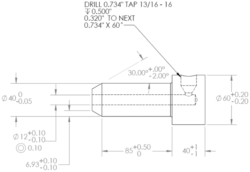
Drawing with tolerances of a 40-mm-diameter tapered tube hydroforming punch.
Figure 8 demonstrates a few more key aspects of scaling down the dimensions of a THF process. First, as the process shrinks, the accuracy of the actuation of the punches must increase in proportion to the geometric scaling factor. Specifically, the transverse motion and angular error in the motion of the punch, represented by Δa and α, respectively, must be kept to a very low level in order to keep the punch from breaking or losing the seal on the tube end. The accuracy of the initial positioning of the tube, represented by Δb, must be similarly improved in order for the regular operation of the punch to be maintained. Another issue with maintaining a seal on the tube end arises from the fact that the length of the plastic deformation on the tube end created as the punch is brought into contact with the tube to create a seal is decreased significantly when the process is scaled to a micro level. This has the effect of increasing the pressure gradient across the tube end and increasing the tendency for the fluid to push the material out of the way and escape confinement. The ability to seal the tube ends is the most crucial component of the conventional THF process, so these sealing issues must be addressed before any THF process that requires feeding can be carried out on the micro level.
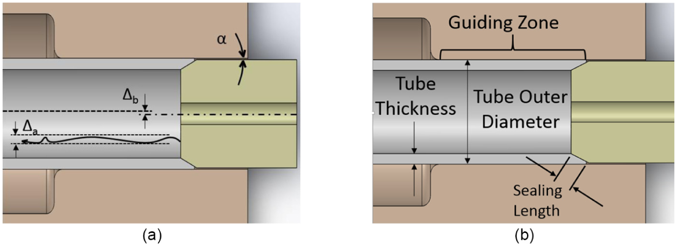
(a) Errors created as a result of positioning and actuation of the punch and (b) major areas of interaction between the tools and the tube.
Considering all of the aforementioned scalability issues associated with scaling down the conventional THF process from a macroscale to a microscale, an important question to ask is, “When should an alternative hydroforming method be considered over the conventional method?” Clearly, the punch is the most difficult aspect of the THF process to scale down, so designers should focus their attention on whether or not a functional punch can be fabricated at a reasonable cost (relative to other hydroforming methods). To this end, they must also consider how often the punches will need to be replaced as a result of damage due to the high stresses in the process. The job of the designer would be greatly simplified if a set of rules were developed to assist in deciding which hydroforming process to use.
Analytical model for determination of maximum induced stresses of the punch
Clarifying the decision on which hydroforming process is appropriate to use can be an arduous task due to the large number of factors affecting the cost of the micro-THF process. To ease this decision, the designer should be able to turn to a set of guidelines which will help them determine the feasibility of scaling down the conventional hydroforming tooling. One such guideline could be to examine the stresses in the punch to determine whether a useable punch can be fabricated.
In order to understand the stress state in the punches, it is first necessary to define all of the forces on the punch. This is done in the diagram shown in Figure 9. The loads consist of normal and frictional loads (Fp and Ff, respectively) at the punch–tube junction and normal and frictional forces (Fw and Fwf, respectively) at the die–tube interface. Additionally, the pressure of the working fluid (Pi) exerts forces on the punch and the tube. The external feeding force (Ffeed) applied to feed the punch into the tube is a function of (1) the axial force which deforms the tube onto the punch taper, (2) the frictional force (Fwf), and (3) the force due to the pressurized fluid acting on the surface of the punch.
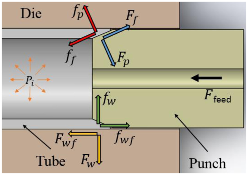
Process forces on the conventional tube hydroforming equipment.
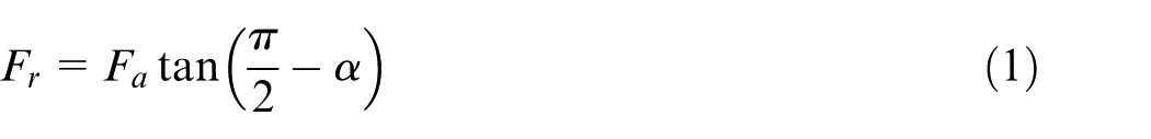
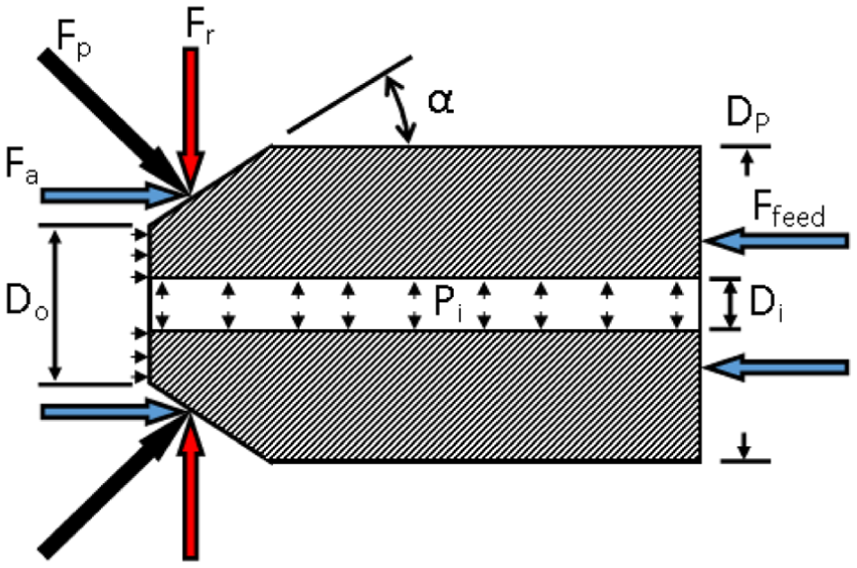
The process forces on the punch can be further broken down into their component forms, as shown in Figure 10. It can be assumed that the shear forces on the punch are small in comparison to the normal force that results from the tube being pressed into the tube and can be ignored for the purposes of this examination. The normal force (Fp) can be broken into two components, axial (Fa) and radial (Fr), using the principle of superposition. The axial force is the force required to feed the tube, and the radial force is then given by equation (1), where α is the angle between the horizontal and the surface of the punch as shown in Figure 10. The feeding force (Ffeed) is then given by the sum of the axial force from the tube and the force of the pressure acting on the punch face
Stresses produced on the surface of the punch as a result of the process forces.
These forces can be translated into pressures acting on the taper by dividing them by the area which they are projected over. To further simplify the analysis of the stresses in the punch, the radial and hoop stresses were determined with the assumption that the punch could be considered a thick-walled pressure vessel. Furthermore, it is assumed that maximum stress in the punch occurs at the tip of the punch, and because of this, the outer radius of the pressure vessel was considered to be the outer radius at the punch tip. The size of the stress in the hoop direction (σh) at an arbitrary radius inside the punch can then be determined using the equation for the hoop stress in a thick-walled pressure vessel, given in equation (2). Similarly, the radial stress inside the punch (σr) is given by equation (3), where Po is the radial pressure on the taper from the contact with the tube (equation (4)), Pi is the internal pressure from the working fluid, ro is the outer radius at the tip of the punch, and ri is the internal radius of the punch (as shown in Figure 11). The Dp and Do terms in equation (4) refer to the outer diameter of the main punch body and outer diameter at the punch nose, as indicated in Figure 10. The thick-walled pressure vessel assumption requires that there is an evenly distributed stress on the flat inner and outer surfaces of the vessel, and that the area being examined is far from the edges of the punch. Strictly speaking, these assumptions are violated in the area of the punch being examined, but it is assumed that the error will be insignificant
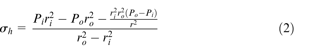
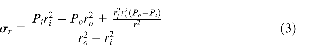
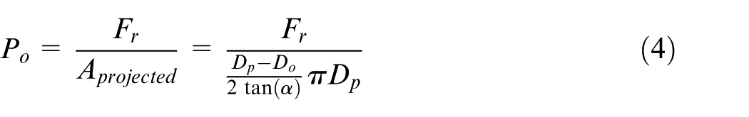
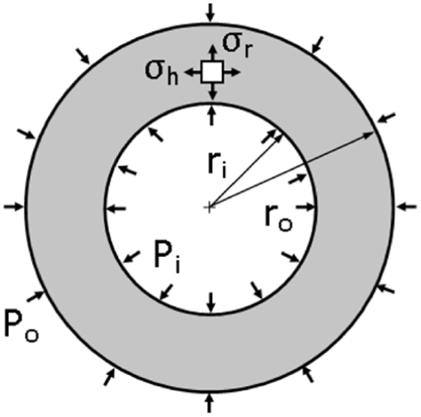
Diagram of the punch nose acting as a thick-walled pressure vessel.
It is assumed that the force used to feed the tube has little influence on the axial stresses at the tip of the punch. Essentially, because feeding force is distributed over the taper of the punch, the total amount of axial force applied to the punch tip is small. The axial stress (σa) is thus the same as the pressure of the working fluid (Pi).
These hoop, radial, and axial stresses are assumed to be the principal stresses and can be used to find the effective (von Mises) stress using equation (5). The von Mises stress can be used to find the maximum stress in the punch material for a given inner diameter and OD, wedge angle (α), feeding force, and applied internal pressure. This stress can then be compared to the yield stress of the punch material to determine whether the punch can be used given the particular conditions of the hydroforming process.

To demonstrate how this model could be used, consider a 1-mm punch with a wedge angle (α) of 20° which is used to hydroform a low-carbon steel tube with a wall thickness of 0.1818 mm when the maximum axial force is applied. The maximum internal pressure was 95.7 MPa, and the force required to feed the tube has been shown to be 320 N (this is explained in detail in section “Finite element simulations of the micro/meso-THF process and model validation”). Using equations (1)–(5), one can plot the maximum von Mises stress as a function of the diameter of the hole in the middle of the punch, as shown in Figure 12. Assuming that the yield stress of the material which makes up the punch is 1500 MPa, one can determine that the maximum allowable hole diameter is about 0.4 mm by finding when the curve crosses the 1500-MPa line. Thus, the punch can only function correctly if the hole on the inside of the punch can be fabricated to a diameter of <0.4 mm. It is clear that this mathematical model can be used to quickly determine the internal diameter required for a hollow tapered punch to withstand the forming forces so long as the feeding force and the tube thickness are known.
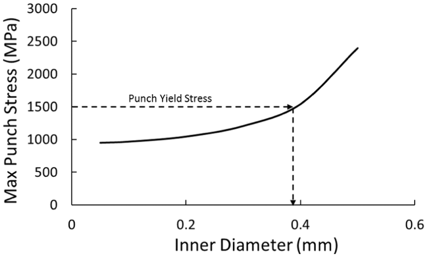
Maximum punch stress versus hole diameter as predicted by the proposed mathematical model.
Finite element simulations of the micro/meso-THF process and model validation
THF simulations used to generate input for punch stress model
Determining the maximum feeding force and thickness of the tube when the maximum force is supplied is more involving. For the purposes of this article, these parameters were determined through the use of finite element simulations of the THF process. The investigation presented in this research was done on tubes with ODs of 1 and 2 mm and thicknesses equal to 10% of the OD, which is similar to the tubes which are commercially available. The length of the tubes was chosen to be 12 times the outer tube diameter (from previous experience, this length was found to allow for the easy handling and positioning of the tube). A T-shaped part was chosen as the final shape of the hydroformed part, and it was decided that the part would not be allowed to thin >25% of the original thickness. The following four materials were chosen to be used as the tube material: SS304, copper, Al 6061-T0, and low-carbon steel. These materials have applications in a broad range of industries, including the medical, electronics, and MEMS industries. The axial feed varied linearly from the start of the process to the end of the process. The maximum feed was set to 2.25 times the tube diameter from each side. The pressure loading path was determined using criteria from an article written by Ghosh et al. 32 and took the form of Figure 13. The feed and pressure loading paths were not optimized because determining optimal loading paths is not a goal of this study. It will be sufficient to simply demonstrate how the model can be applied to any hydroformed part, as long as the loading paths are representative of a real operation.
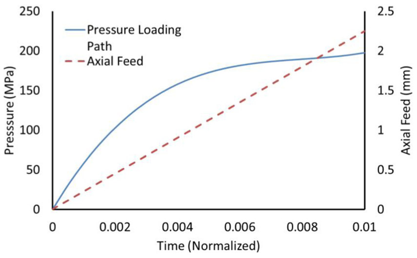
Pressure and axial feed loading paths.
The finite element simulations were carried out using the explicit dynamics module of ANSYS Workbench 15. The die was modeled as a rigid body and meshed with tetrahedral elements, while the tubular blank was modeled as a rigid plastic body and meshed with shell elements. The material properties of the tubular blank were assumed to follow the power law (
Material properties used to define the workpiece.
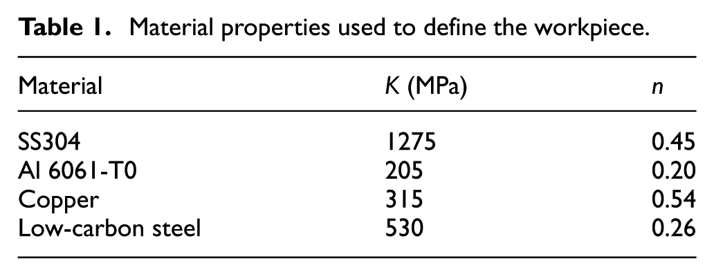
Figure 14 shows the thickness distribution of one of the simulated parts, and one can see that the load paths chosen create an adequate part for the purposes of this study. A total of eight simulations were run, and the results are presented in Figures 15–17. Figure 15 clearly suggests that the maximum feeding force is highly dependent on the flow stress of the workpiece, as tubes made from the stainless steel and steel materials required much higher loads to feed the workpiece than those made from copper and aluminum materials. Based on analysis of Figure 16, the thickness of the tube ends appears to be more dependent on the strain hardening exponent than the strength coefficient of the material. Specifically, as the strain hardening exponent increases, the thickness of the tube end decreases. The heights of the bulges formed in the simulated parts are given in Figure 17, which shows that all simulated parts were adequately formed. The results which will be used in the mathematical model to determine the punch stresses are the feeding force and the tube thickness when the maximum feeding force is applied.
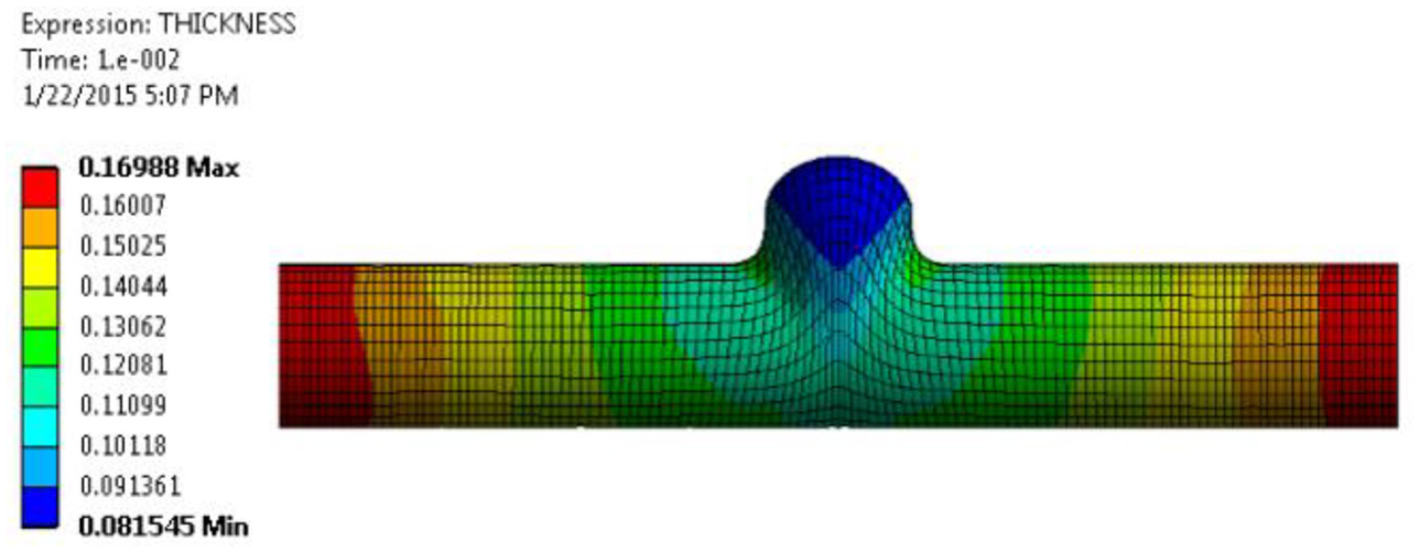
Thickness distribution of the 1-mm-outer diameter stainless steel part.
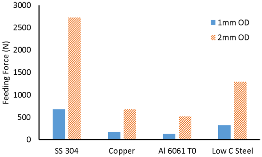
Maximum force required to feed the tube ends axially.
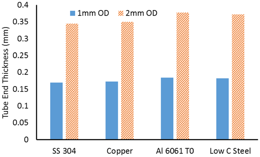
Thickness of the workpiece at the tube ends.
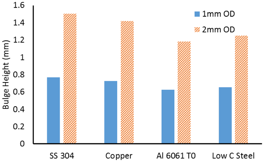
Bulge height of the hydroformed part.
Comparison between analytical model and numerical modeling results
In order to validate the results of the mathematical model discussed in section “Analytical model for determination of maximum induced stresses of the punch,” structural simulations of the punch were done. These simulations were carried out using the static structural module of ANSYS Workbench 15. The punches were modeled as axisymmetric, elastic bodies with Young’s modulus of 200 GPa and Poisson’s ratio of 0.3. The geometry of the punch used in these simulations is detailed in Figure 18. The reaction force between the tube and the punch is applied to the length of the taper such that the sum of the radial and axial components is normal to the taper. The forming pressure is applied to both the inside of the punch and the flat face at the punch nose. The back end of the punch was allowed to move in the radial direction but was fixed in the axial direction.
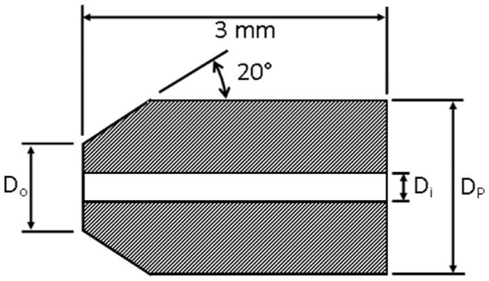
Geometry used in the static structural punch simulations to verify the model assumptions.
The results of one of the simulations are shown in Figures 19 and 20. This particular simulation corresponded to the hydroforming of a low-carbon steel tube and used an applied feeding force of 320 N, an applied pressure of 95.7 MPa, and an internal diameter of 0.4 mm. One can see that the maximum stress does occur at or very close to the tip of the punch. It is important to note that the maximum stress in the punch moved slightly away from the punch tip in some of the simulations, but the shift is small enough that the assumption can still be considered valid. Based on the plot of the normal stress along the axis of the punch (Figure 8), one can see that the second major assumption, that the axial stress at the punch tip is equal to the internal pressure of the fluid, is also validated by the finite element model. Furthermore, these results match very well with the analytical model for the maximum punch stress presented in section “Analytical model for determination of maximum induced stresses of the punch,” which predicts a maximum stress of 1541 MPa for the punch, in comparison to the 1633 MPa stress predicted by the finite element model (an error of about 5.6%). A further comparison of the model and finite element simulations of the stresses in the punch is given in the next section, where the model is used to create guidelines for the micro-THF process.
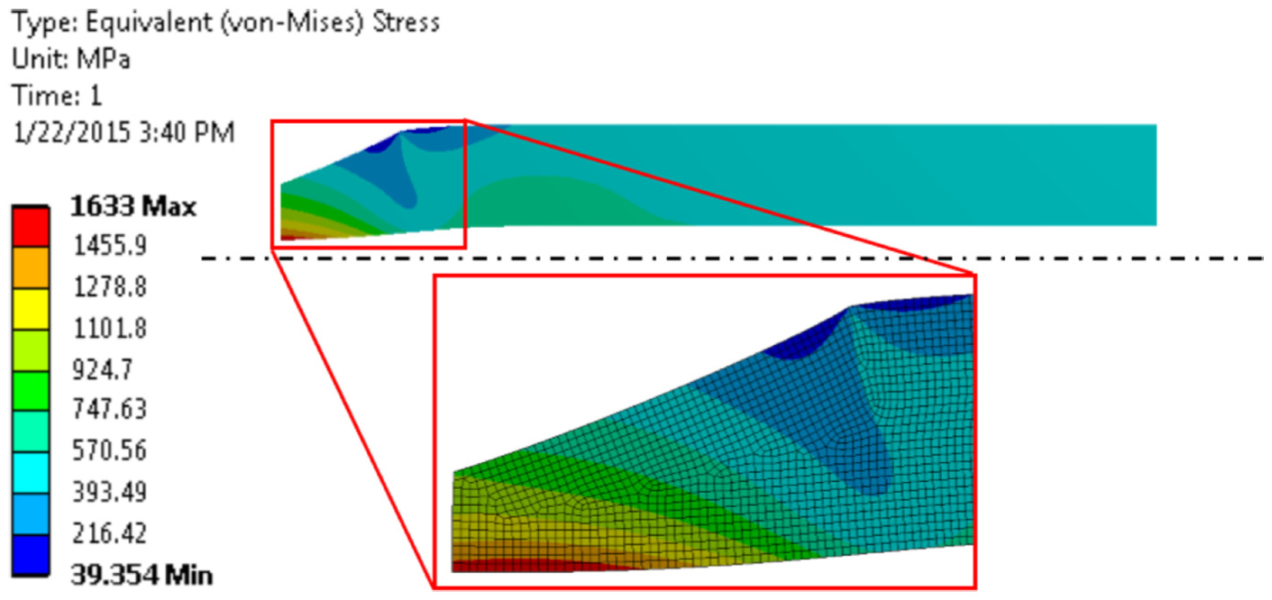
von Mises stress in the tapered punch.
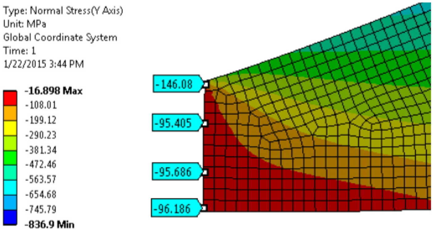
Axial stress at the punch tip.
Design guidelines for micro/meso-THF punch systems
The purpose of the mathematical model was to give the designer a tool to use when deciding whether or not it would be feasible to fabricate micro-tapered punches. Specifically, the mathematical model tells the designer how the stresses in the punch will change as a result of changes in the punch’s hole size. In order to better understand the trends associated with a changing hole size, and how it affects the feasibility of scaling down conventional hydroforming tooling, the mathematical model was applied to the eight hydroforming cases simulated in the previous section. The stresses predicted by the model are compared to the stresses predicted by finite element simulations of the punch as shown in Figures 21–24.
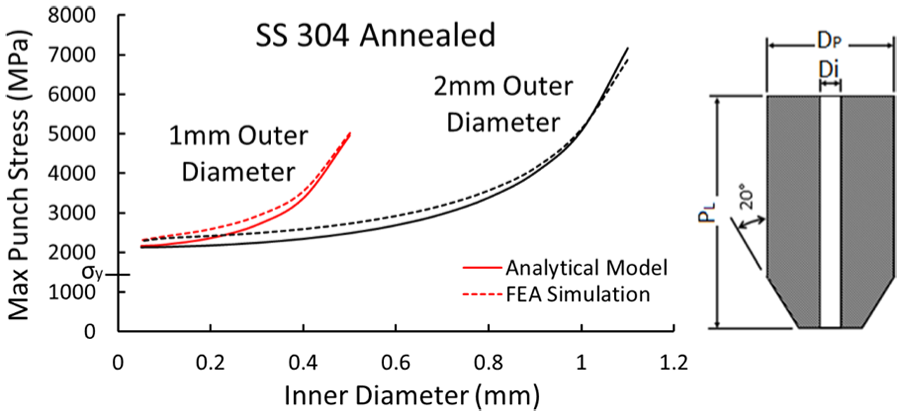
Maximum punch stress as a function of inner diameter for the hydroforming operation on the stainless steel tube.
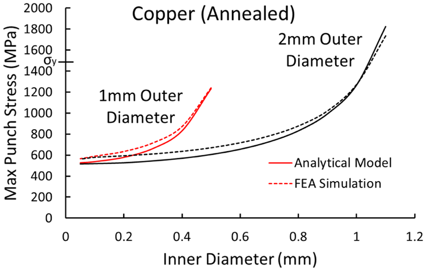
Maximum punch stress as a function of inner diameter for the hydroforming operation on the copper tube.
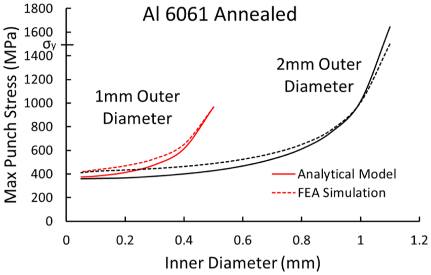
Maximum punch stress as a function of inner diameter for the hydroforming operation on the aluminum tube.
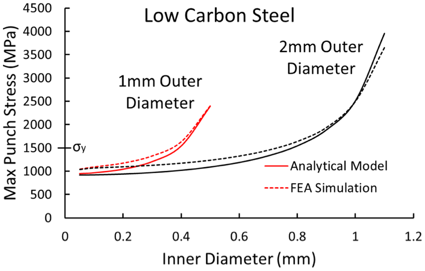
Maximum punch stress as a function of inner diameter for the hydroforming operation on the steel tube.
The results of the analytical model seem to agree well with the simulation, except for an under prediction of the stresses in the punch. The error in the plotted range is 10%–15% and is likely a result of the maximum stress actually occurring a slight distance away from the tip of the punch. The error increases as the thickness of the punch tip becomes infinitesimally small, but in general, the stresses in this range will be so high that the punch will be unusable. Therefore, the results of the model in this area can be considered inconsequential.
In order to understand how the model might be applied to a design problem, consider the following example. The designer wants to design a THF process that creates T-shaped parts like the ones which were used as inputs to this model. After determining the various pertinent process variables, the designer plugs them into the model, generating the curves in Figures 21–24. It is generally held that a hardened tool steel can reach (compressive) yield stresses of up to 2000 MPa, but a factor of safety should be applied so that errors in the analysis and variations in the process do not cause the failure of the punch. Therefore, it will be assumed that the punch will yield if the stress reaches 1500 MPa. It can be seen that the hydroforming of copper and aluminum tubes created conditions where the conventional punch could easily handle the stresses which are likely to occur. However, the stresses resulting from the hydroforming operation on the low-carbon steel and the stainless steel show that there are considerably higher stresses associated with tougher tube materials, as expected. Furthermore, as the hole in the punch increases in size and approaches the OD of the punch nose, the stresses in the punch rapidly increase.
In the case of the low-carbon steel hydroforming operation, the stresses in the punch transition from the acceptable range to the unacceptable range at a hole size of 0.4 mm for the 1-mm punch. For the 2-mm punch, the transition occurs at double the hole diameter, in line with the geometric scaling applied to the hydroforming operation. If the designer can only accurately drill 0.5-mm holes in a punch with an OD of 1 mm, then the tapered punch cannot be used to hydroform the 1-mm-diameter steel part but would be acceptable for a 2-mm part. The punch stress analysis on the hydroforming of the stainless steel part resulted in stresses that well exceeded the acceptable range of tool steels for any hole diameter, meaning that there is no hole size which would make a strong enough punch to be used in this operation. These stresses are high because the tube is relatively long and thick due to the limitations discussed in section “Scalability of THF workpiece.” On the macroscale, these limitations can be avoided, thanks to the lack of the size effect which allows for lower frictional resistance and, thus, lower punch stresses. It is important to note that the two sets of curves were generated using geometrically proportional models in order to illustrate the effects of simply scaling the process and does not account for the fact that it is possible to use proportionally shorter tubes when the diameter of the tube increases. The reduction in the length of the tube in the guiding zone, relative to the OD of the tube, would result in a reduction in the punch stresses, likely to an acceptable range.
In cases where the designer could not have a tube manufactured that could withstand the stresses predicted by the model, there are two options: (1) reevaluate the loading paths used in their THF operation or (2) use a nonconventional THF method, which is not subjected to the same conditions as the tapered punch.
Conclusion
The scalability of the THF process is affected by numerous variables from changing material properties in the workpiece to difficulties in maintaining tight tolerances when fabricating very small tools. The main goal of this study was to investigate the feasibility of scaling the traditional macro-sized THF tools to the microscale. This was accomplished through a combination of conceptually observing the effects of scaling the tooling in a qualitative manner, and the application of a mathematical model aimed at determining the stresses in the traditional tapered punch. The major conclusions which were drawn from this study were as follows:
The THF process is mainly affected by the ability to make small and accurate features on the punch and the changing of the workpiece behavior on the microscale.
The effect of scaling down the conventional tapered punch on the maximum punch stress can easily be seen through the application of a simple mathematical model, which considered the punch as a thick-walled pressure vessel.
As the punch shrink’s, the maximum allowable hole size also shrinks. This creates a problem as the current manufacturing techniques are not capable of accurately creating holes which are small enough to bring the punch stresses to an acceptable level.
If the designer determines that the stresses in the punch will be too large for the smallest hole they can create in the punch, a nonconventional THF strategy, such as one using the floating die–THF tooling, discussed in section “Introduction,” will have to be adopted.
Footnotes
Declaration of conflicting interests
The author(s) declared no potential conflicts of interest with respect to the research, authorship, and/or publication of this article.
Funding
The author(s) received no financial support for the research, authorship, and/or publication of this article.