
Abstract
This article is the review of hydroforming technologies that have been used increasingly in various industries including automotive applications. General concepts and technological developments in tube hydroforming and sheet hydroforming are presented with recent research and development activities. Then, the theoretical background associated with the plasticity and constitutive laws and their implementation to the computational modeling of the hydroforming process are discussed.
Keywords
Introduction
Hydroforming is a wide spread technology in many industrial applications, which are generally manufactured by the pressure-assisted processes. The hydroforming processes are usually known to have numerous advantages over other conventional stamping-based processes in terms of weight reduction, improved part quality, increased strength and cost saving for tooling.
The hydroforming technology is generally classified into the tube hydroforming (THF) and sheet hydroforming (SHF). The SHF has been an alternative to the conventional deep drawing and stretch forming process. In this process, tools in the sheet stamping process are replaced with the fluid medium, which reduces the tooling cost significantly and improves the surface quality of the formed parts. In the THF, on the other hand, the original tubular-shaped parts are further formed into the final products by applying internal pressure and axial forces inside a suitable die. The desired shapes are achieved by the proper control of the hydraulic pressure and feeding force. Although these two methods are distinctive in terms of the shape of the part before forming process, they are common in that they use the fluid pressure or hydraulic pressure.
Interest and research in the hydroforming technology for industrial applications have been growing rapidly, especially in the automotive industry. There are numerous research articles and review articles for the hydroforming process. In addition, for the THF technology, the international conference series “Tube Hydro” has been held biennially. This conference raised lots of technical issues on the THF and SHF technology such as the industrial application development, solutions and mass production and quality control.
Although the hydroforming technology has been regarded as already well-established one, there are still many issues that should be overcome before successful applications for future automotive or other relevant industries. The current review focuses on the recent research activities of the hydroforming technology starting from the review of the two main processes and then highlights the issues on the materials and computational modeling applied for the technology. Three main topics in hydroforming discussed in sections of this document are as follows:
Tube Hydroforming;
Sheet Hydroforming;
Computational modeling.
In particular, in the last topic, the constitutive modeling in the hydroforming process for the emerging materials will be discussed, which may be very useful in finding new opportunities in the future progress of the hydroforming technology.
THF
Introduction to THF
THF is a manufacturing process that allows the fabrication of thin-walled structural components of varying cross section along their length. In addition, THFed components can have a curved and non-planar axis. Hence, a design can be optimized for strength, stiffness and weight, which serves to explain the popularity of THF in the automotive and transportation industries. It also differentiates the hydroformed components from those that are extruded and then bent; that process sequence can lead to complex shapes but no axial variation in the cross section.
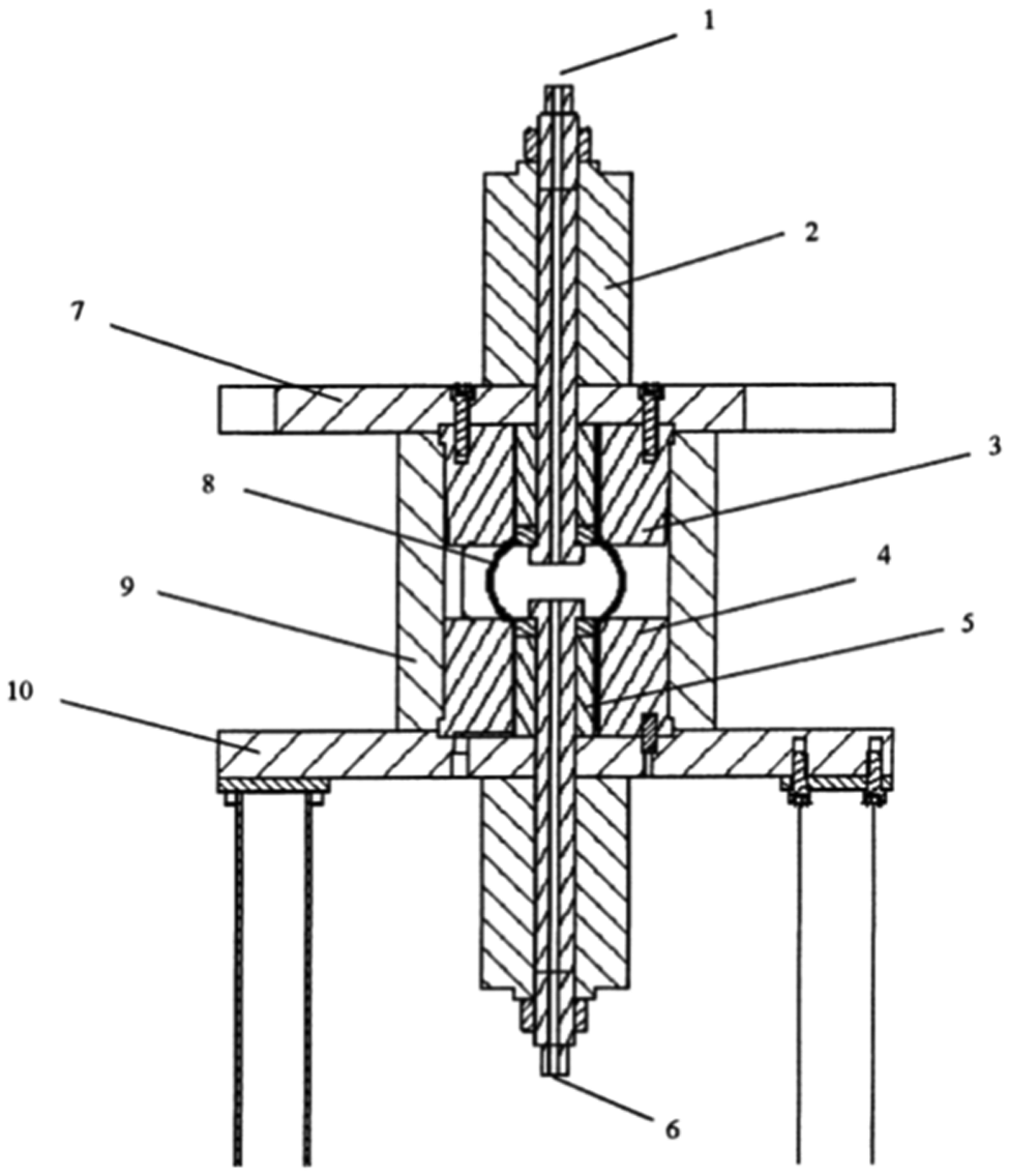
Typically, one starts with a circular–cylindrical tube that is placed inside the forming die. The tube is engaged from one or (usually) both ends with hydraulic actuators that are also used for filling the tube with the pressurizing medium (usually, a fluid) and for providing sealing during the subsequent pressurization. A schematic of such a setup is shown in Figure 1.
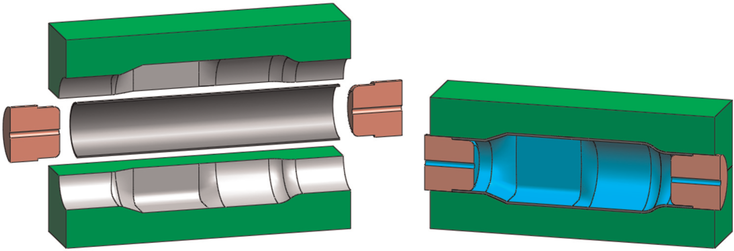
Principle of tube hydroforming.
To increase the process flexibility, THF is often combined with secondary, in-tooling processes such as hydropiercing 1 and nut inlaying (see next section). A typical hydroforming machine consists of the tooling, the hydroforming press and the pressurization system. Often, this is combined with other hydroforming machines, tube benders, laser cutting machines and robotic handling to form a hydroforming cell that receives tubes in bundles and yields hydroformed components. Typical specifications of a hydroforming machine include a pressurizing capacity of 2000 bar and a die closing force of 100 MN.1,2
In order to achieve larger expansion ratios (i.e. the ratio of final to initial perimeter of the component) and more complex cross-sectional shapes, a number of process variants have emerged. Numerous recent ones are described in the next section. Here, only the distinction between the conventional, high-pressure hydroforming (HPH) described above and low-pressure hydroforming (LPH) is explained. In LPH, a larger diameter tube than in HPH is used. The tube is crushed as the die is closing and then it is inflated. The idea is to have enough material in the die to be able to inflate to the desired shape without stretching, and thus avoid or delay burst. This allows for larger expansion ratios than what are possible in HPH and requires lower pressures than HPH.1,3,4
The two control parameters (or degrees of freedom) in THF are the internal pressure (or, less commonly, the flow rate) and the axial displacement. Depending on the combination selected, the failure modes of Figure 2 can be avoided and a sound component can be formed. For example, insufficient axial feed will result in low axial load and sealing of the tube during inflation will not be possible. On the other hand, excessive axial load will wrinkle the tube walls or even buckle the tube as a column (Euler-type buckling).
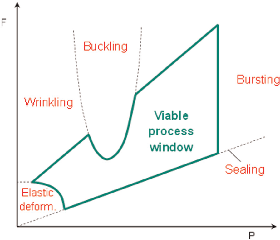
Working envelope and failure modes in THF. 5
An example of a successful loading path is shown in Figure 3 5,6 (also see Zheng et al., 7 Asnafi 8 and Manabe et al., 9 for other examples). In that case, a long and slender tube (length=610 mm, length/diameter = 10) was expanded to a square with rounded corners. The expansion ratio (ratio of final to initial periphery) was 1.18. The tube was at first inflated with low axial feed, to bring it in contact with the surrounding die and avoid column (Euler-type) buckling. With the tube thus stabilized, the axial feed was increased rapidly to feed material inside the die. Finally, as the axial feed was exhausted, the internal pressure was increased further to improve the die and corner filling (calibration).
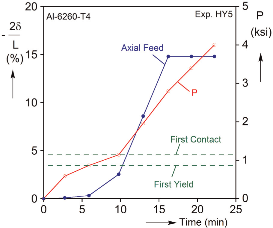
Example of a successful loading path for high-pressure THF of Al-6260-T4 tubes. 6
Some recent developments in THF
THF has a history of more than 100 years. 10 However, it has evolved into a mature manufacturing technology only in the last 15–20 years. Starting from the mid- to late-1990s, its applications in the automotive and bicycle industries have exploded, while its applications in transportation, aerospace, appliance and biomedical industries are expanding. In this section, a few of the more recent major developments are described as an indication of the state-of-the-art and future trends.
THF with axial feeding
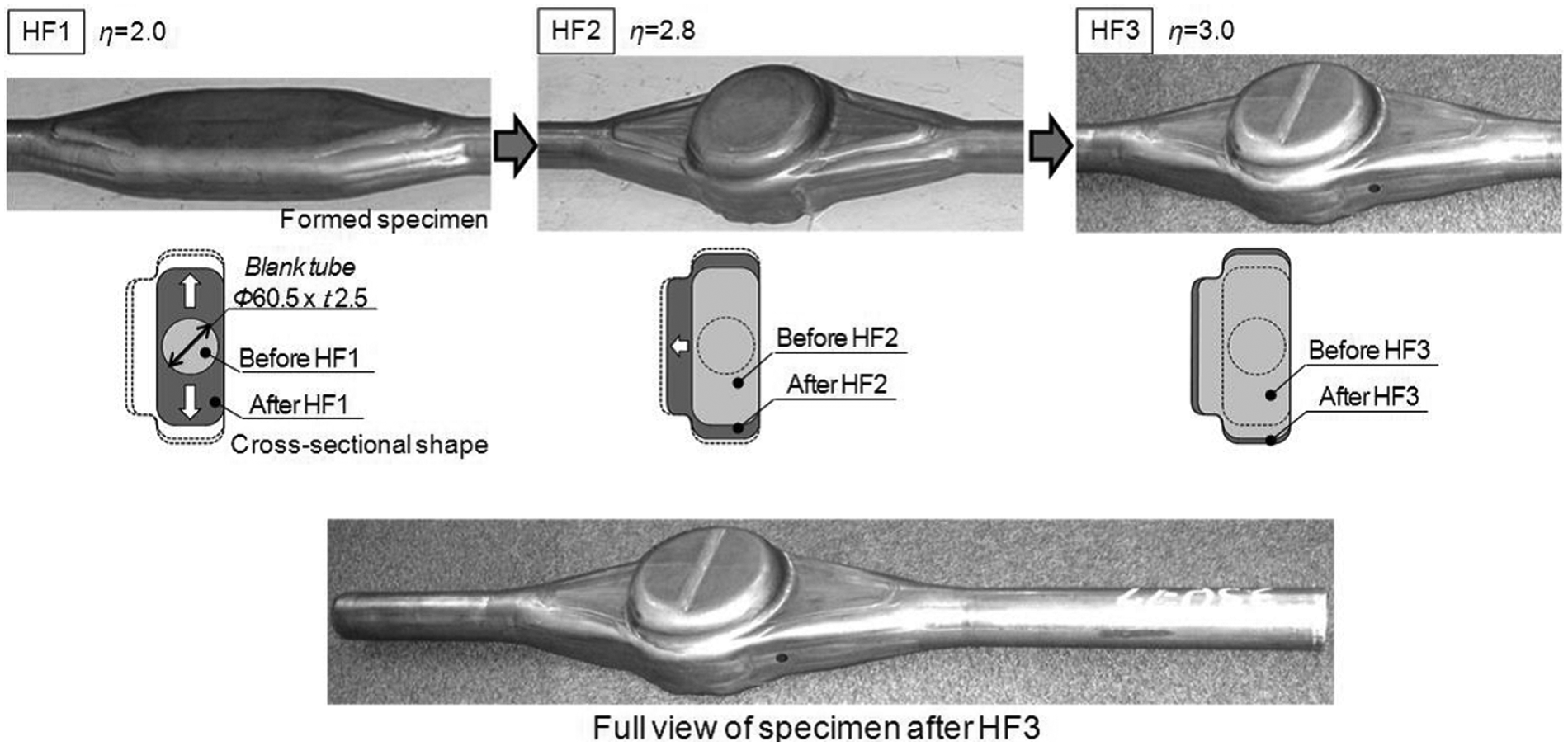
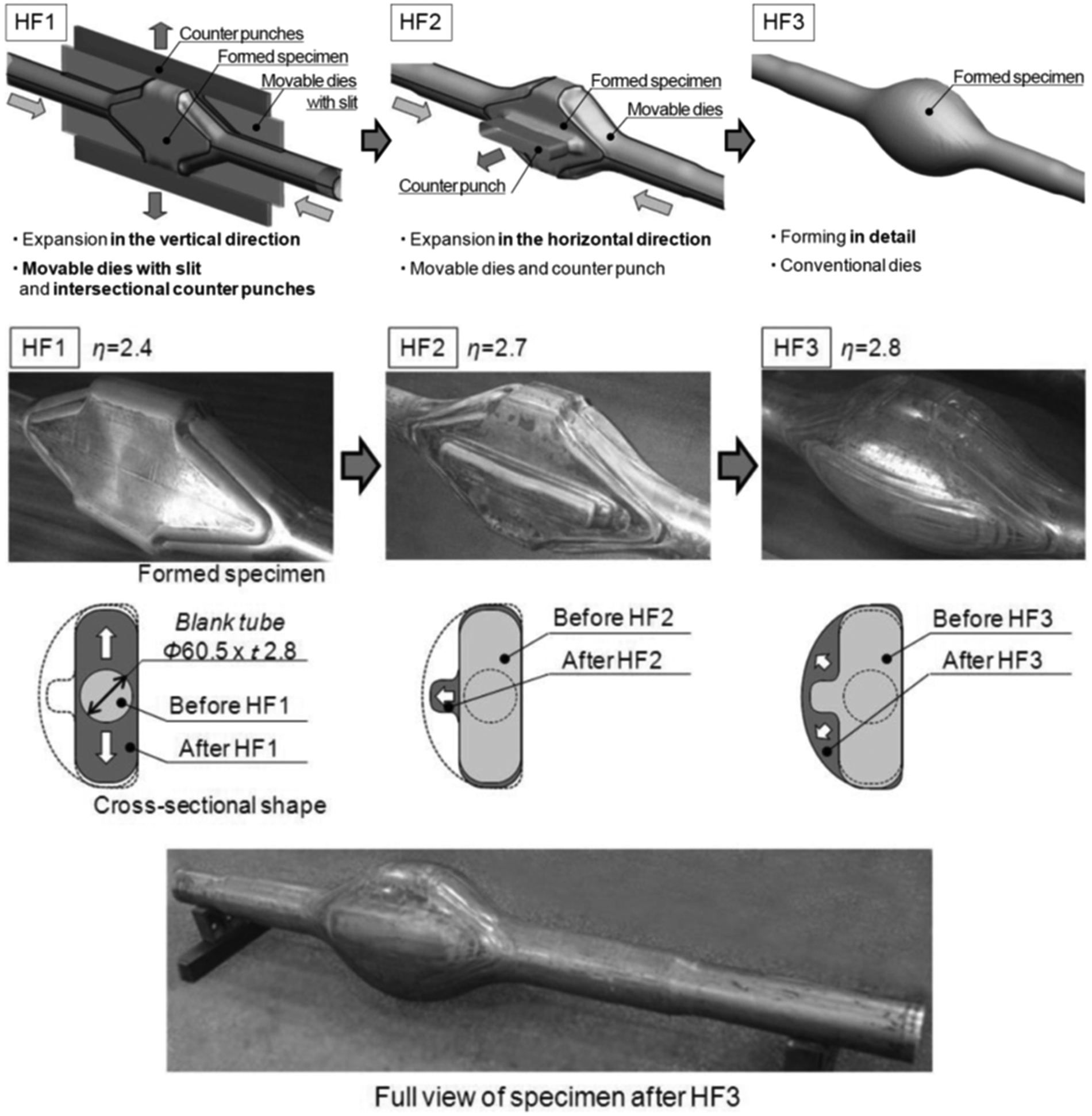
The pursuit of large expansion ratios has always been of interest in THF. One of the largest ratios reported to date comes from the work of Nippon Steel shown in Figures 4 and 5.11,12 As shown in Figure 4, a mild steel tube (STKM11A) was first expanded in the vertical direction using Nippon Steel’s intersectional movable dies technology. In that case, the hydroforming die consists of multiple intersecting components. Some of them have the ability of sliding (receding) along the tube axis as the tube is inflated. At the same time, other components recede in the direction that the tube is expanding. An expansion ratio of 2 was achieved in this way. The second step (HF2) was formed using conventional movable dies (also known as counter-punches). Then the last step (HF3) was performed in usual (i.e. rigid) dies. Through proper design of the counter-punches, enough material can be accumulated in the forming die so that it can be expanded in the next step without failure (see Figure 5). Note that no annealing was required between the forming steps shown in Figures 4 and 5, despite an expansion ratio of 3.
The idea of increasing the expansion ratio by feeding or placing an excessive amount of material in the die has led to the concept of “beneficial wrinkling.”13–22 This is shown in Figure 6. The tube is either preformed to a shape with axisymmetric wrinkles and then placed in the die or, preferably, it is first compressed excessively while in the die so that it wrinkles (see Figure 2) and then inflated. In some cases, wrinkling has been induced with the use of external rings that are subsequently removed from the tube (Figure 7). Note that these methods can also be used for manufacturing of metal bellows.23–26
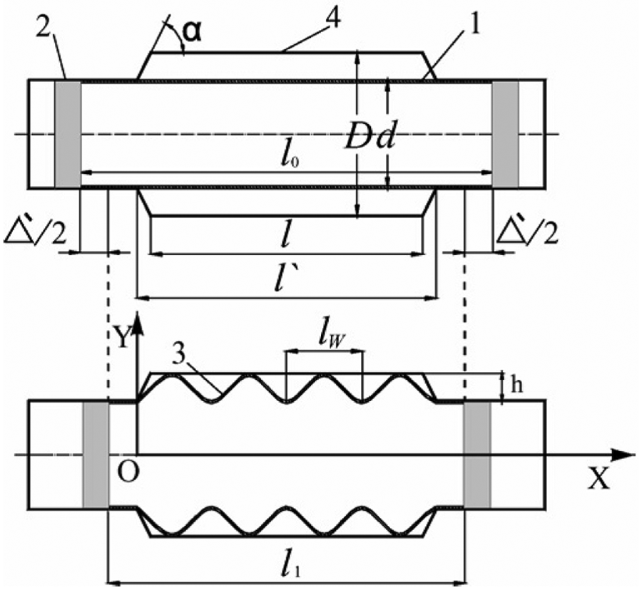
Principle of beneficial wrinkling for THF. 18
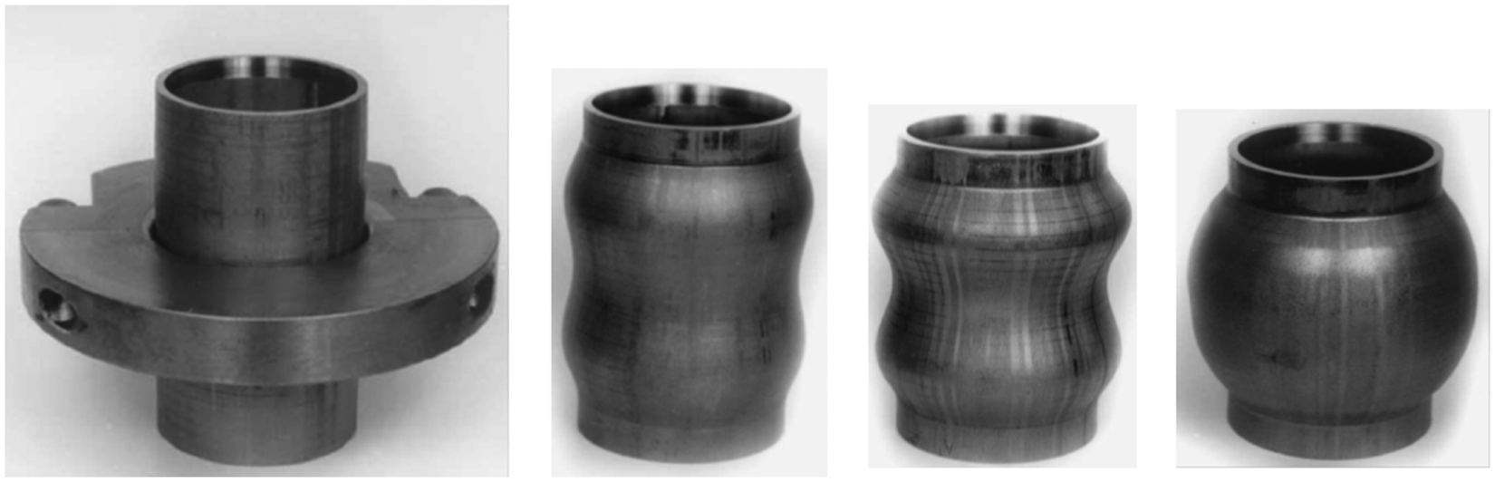
Tube inflation by beneficial wrinkling controlled with an external ring. 15
A major challenge in this approach is that the formation and growth of wrinkles must be controlled very closely. While this is easier in elastic wrinkling, the case of plastic wrinkling presents difficulties, as wrinkles tend to form sequentially: as the end displacement is increased, a single wrinkle is formed, grows independently until it folds on itself and then the cycle is repeated. Numerous examples in the literature above show how this can be averted by proper selection of the loading path. For example, Yang and Ngaile 13 performed analytical, numerical and experimental work on beneficial wrinkling in THF of 304 stainless steel. They expanded an earlier model by Kyriakides and colleagues27–29 to THF. A successfully formed example from 304 stainless steel is shown in Figure 8.
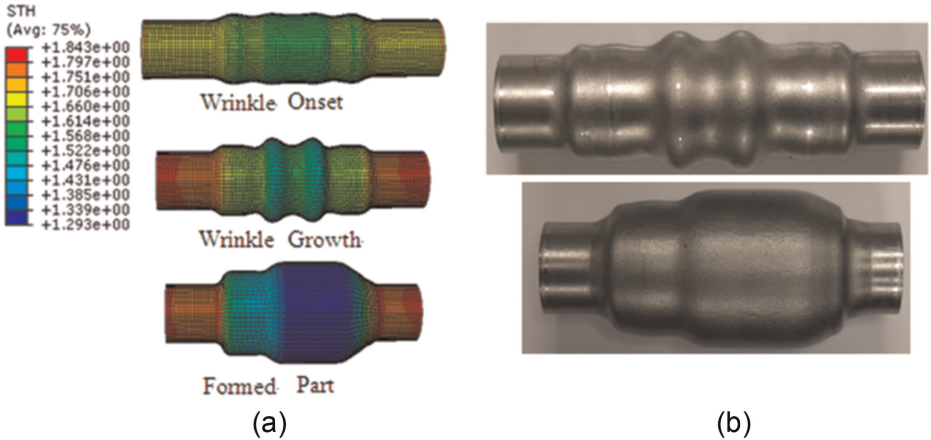
(a) Numerical simulation and (b) successfully formed component from SS304 utilizing the concept of beneficial wrinkling. 13
Pulsed tube hydroforming
Another way of enhancing the hydroformability is the pulsed tube hydroforming (pTHF) method, proposed in Japan 30 (Figure 9). It was discovered that a slowly varying application of the pressurization (order of 1 Hz) was capable of averting the bursting failure shown in a conventionally formed component.
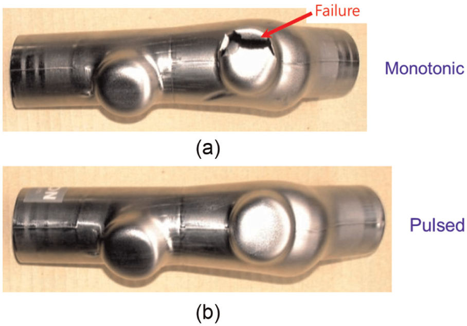
(a) Conventional and (b) pulsed hydroformed component. 30
It was initially thought that a major improvement of the pTHF over the conventional technique was that the pulsing led to a cyclic attachment and detachment of the tube on the die wall, which improved the lubrication and hence permitted the easier flow of the material. However, in subsequent experiments on free inflation of tubes, a similar formability enhancement was discovered; see Figure 10. 31 In these experiments, two families of tubes were tested: one with a length-to-diameter ratio of 1.6 (short tubes) and another with 4 (long tubes). In each case, the end displacement was decreased monotonically. In the mean time, the internal pressure was as follows: (a) ramped and oscillated, (b) ramped and held at a high level and (c) ramped and held at a lower level. In the first case, a uniform component was formed. In the second case, the tube burst, while in the third case the tube wrinkled. Through numerical simulation as well as observations of the tube during the experiment, it was determined that the tube shape alternates between axial wrinkling (when the pressure is dropping) and inflation (when the pressure is increasing).
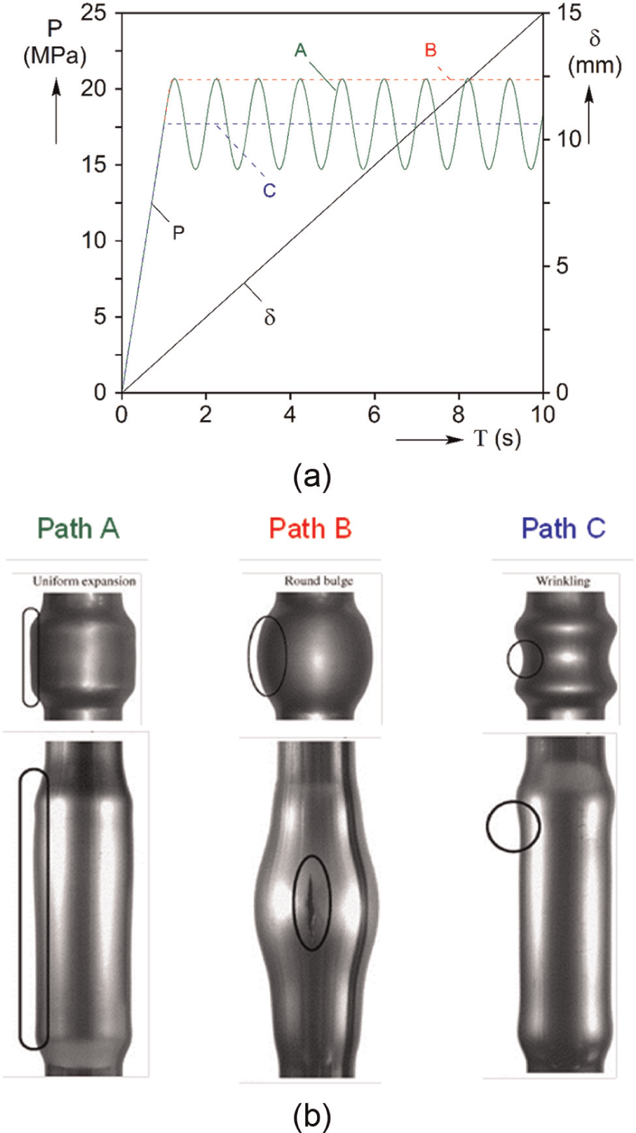
(a) Loading histories and (b) freely inflated tubes, showing uniform deformation, bursting or wrinkling, depending on the loading path. 31
In that sense, pTHF can be viewed as the dynamic, incremental version of THF with beneficial wrinkling, described earlier. Indeed, depending on the application, one method or the other might be more suitable for producing a component. The situation becomes more complex when the material is susceptible to deformation-induced heating and/or phase transformation. In a recent investigation, Cullen and Korkolis 32 established that the apparent enhancement in ductility during pulsed tensile loading of 304 stainless steel is due to the different durations of the pulsed and the monotonic test, and hence the different temperature gradients that develop in the two cases. These gradients lead to non-uniform weakening of the material, and hence act as imperfections that trigger an earlier localization of failure than in the ideal isothermal case. When a phase transformation occurs during forming (e.g. a strain-induced martensitic transformation or the transformation-induced plasticity (TRIP) effect), there is evidence of enhanced ductility. 33 However, the extent that these mechanisms are influenced by the presence of the thermally conductive pressurizing medium and the contact of the deforming tube with the cool die is not presently known. Naturally, predicting the material behavior in these cases becomes even more complex. 34
Warm THF
For working with less ductile materials, such as aluminum and magnesium alloys that are of interest to the automotive industry for lightweight vehicle bodies, warm THF has been used. The working medium is either hot oil or hot gas. Typical forming temperatures are up to 300 °C for Al35,36 and Mg.20,37–41 Following the trend in the automotive industry of using press-hardened components for the crash-sensitive parts of the car body (such as the B-pillar) by hot stamping of boron steel sheets, 41 similar efforts are reported in THF. As in the hot stamping of sheets, proper control of the die temperatures can yield components with varying microstructures along their length, tailored to their specific application. For example, the center of a B-pillar can be very hard, so that it will remain elastic and stiff in the case of a side impact and hence minimize the intrusion to the passenger cage, while the ends can be made softer, to prevent premature failure at these locations. The major complication in hot-THF is the selection of a suitable working medium. Nitrogen was used in Neugebauer et al. 41 and hot air in Maeno et al. 42 The tube can be pre-heated by placing it in an oven, by resistive heating 43 or inductive heating, oftentimes performed in the die. In the latter case, the inductive coil can be placed inside the tube, to offer more direct heating at the expense of more complex tooling design. 44 Oxidation of the surface can be prevented by forming in a CO2 atmosphere. In an investigation of hot-THF of 22MnB5 boron steel tubes, 45 ceramic powders and sand (silicon dioxide) were used instead of a hot gas. The advantages claimed were a shorter time to build up the pressure required, and more safety than using gas media.
Other THF processes
THF can also be used for microtubes (diameters around 1 mm or less). The challenge here is that at these small sizes the tubes are relatively thick, hence the internal pressure required for forming can exceed 4000 bar. 46 This requires not only special pressure intensifiers but also very stiff dies and special tube-end sealing systems, since the cycle time has to remain reasonable.47,48 Typical applications are in the biomedical field, as well as in microfluidics, water-cooled heat exchangers for microchips, sheaths for fiber optical cables and so on.
There have been numerous investigations and attempts to take advantage of the enhanced ductility of metals under high hydrostatic pressure. In the context of hydroforming, this is termed double-THF, and the tube is inflated against an external pressure (or back-pressure) by a pressure differential. While the process has the obvious benefit of enhanced ductility, the pressures required can be very high and the die has to be designed as a pressure vessel, to contain the external (to the workpiece/tube) pressure. Perhaps, the first application was reported by Fuchs, 49 who demonstrated the effect by achieving 100% expansion (or, expansion ratio = 2) on copper tubes. In recent analytical investigations, Wang and colleagues50,51 and Smith et al. 52 demonstrated that the external pressure can delay burst. Subsequent experimental work highlighted the difficulties in obtaining significant improvements within a range of pressures that were considered practical for applications. 53 However, in a recent experimental investigation, 54 it was demonstrated that a tube expanded to a square shape against an external pressure of 800 bar could sustain significant thinning without burst.
Other recent applications of THF include the following: (a) using internal pressure to eliminate the wrinkles from bending thin-walled tubing (e.g. Harley-Davidson motorcycle frames); (b) hydro-embedding (e.g. hydropiercing and inlaying of nuts), to aid in the assembly of the hydroformed component;55,56 (c) joining by THF; 152 (d) THF of tailor-welded tubes 11 and (e) discrete multi-layer hydroforming.56,57 Diverse components, such as turbine blades 58 and structural joints, are oftentimes hydroformed 59 (see Figure 11). Furthermore, lightweight materials that resemble metallic hollow sphere (MHS) topologies can be produced with hydroforming and subsequent assembly. 60
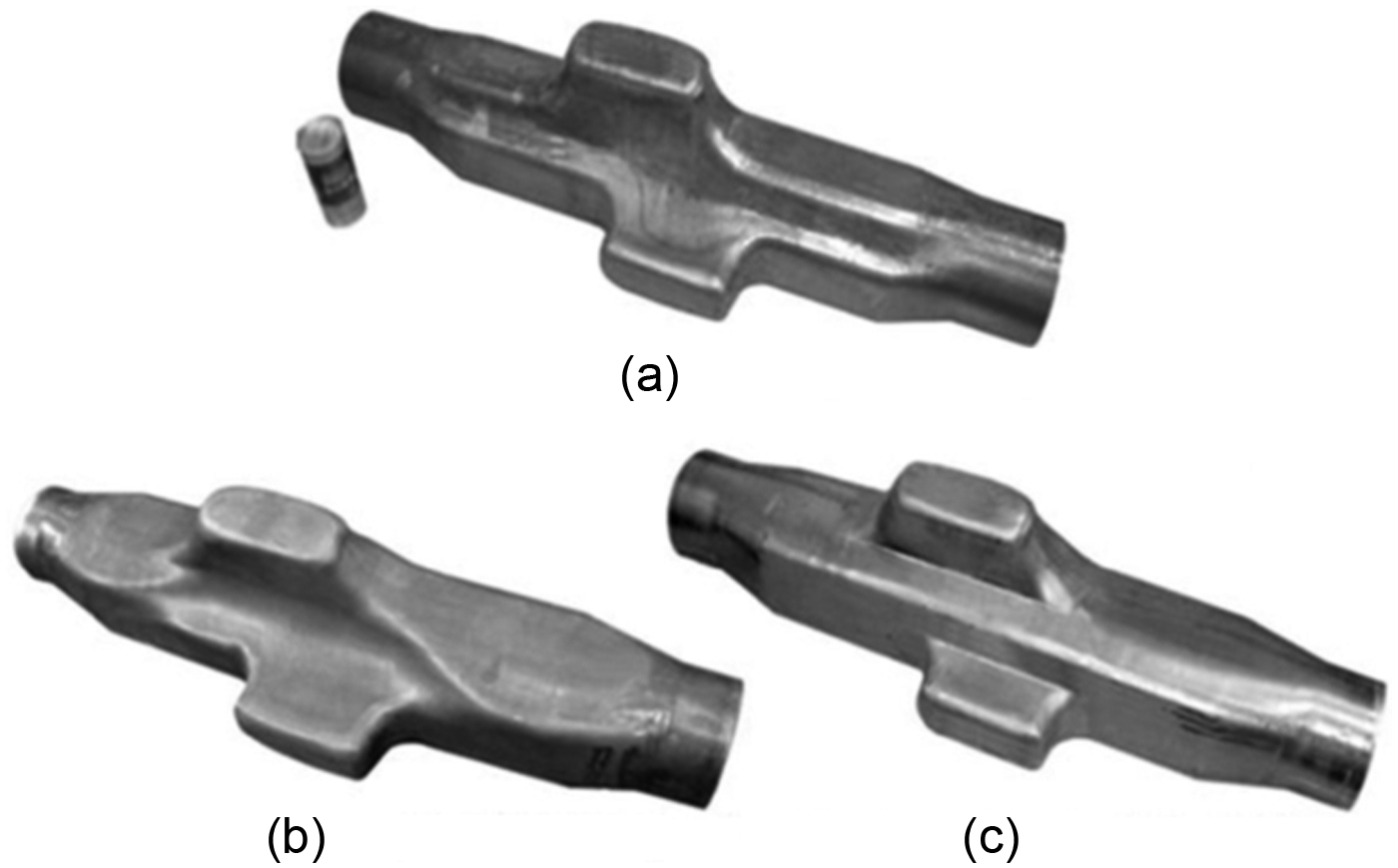
Hydroforming of a structural joint with two branches: (a) base shape joint, (b) curve-shaped joint and (c) ridge-shaped joint. 59
Materials in hydroforming
In general, any sheet materials applied to the cold stamping can be available candidates for the hydroforming process. However, recent needs for structural designs reducing the weight of the automotive body and eventually improving the fuel efficiency drove the applications of the advanced high-strength steels (AHSS) and lightweight alloys such as aluminum alloys, magnesium alloys and titanium alloys in the hydroforming technology. 61 Regarding the AHSS, dual-phase steels (DP steels) and TRIP steels have been frequently used for their high strength and good ductility, so that the automotive components can be manufactured without increasing temperature during the process. On the other hand, since the lightweight alloys, that is, aluminum alloys and magnesium alloys, show limited formability at room temperature, most of the automotive components are formed at elevated temperatures for enhanced formability. For instance, fabrication of complex shaped structural components with wrought aluminum alloy could be made at the temperatures of 150 °C–300 °C, 62 and recent development for the warm stamping and hydroforming has drawn significant attention for magnesium alloy sheets, too.63–66
The above trend in the hydroforming technology is well reflected in the recent research activities among the hydroforming society. Figure 12 summarizes the number of presentations at the recently organized Tubehydro 2013 conference 67 in which various materials were investigated. From this figure, steels take the largest portion, which includes the AHSS, especially DP steels. The second largest population that was investigated in the hydroforming technology is aluminum alloys, for which the warm forming was usually applied to enhance the formability. Magnesium alloys and titanium alloys are also utilized to reduce the weight of automotive or aircraft.
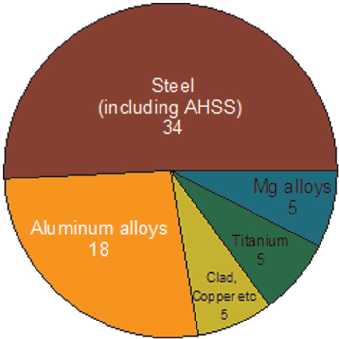
Number of articles presented in the Tubehydro 2013 conference, in which various materials were researched for the hydroforming technology.
Material characterization for modeling of THF
Accurate assessment of material behavior is necessary for reliable numerical simulations of THF. In comparison to the conventional sheet metal forming processes, THF has numerous peculiarities that require a unique approach to assessing plasticity and failure.
The first complication comes from the fact that the material is available in tubular form. Hence, many of the popular ways for measuring the plastic anisotropy and the forming limits are difficult to implement. For example, for the case of plastic anisotropy of a rolled sheet, it is customary to extract tension specimens at different angles to the rolling direction and measure the hardening curve and the R-value (Lankford coefficient) (see Figure 13). These are then used as inputs to calibrate anisotropic yield functions.68–70 In contrast, the same information is very difficult to be obtained from tubular specimens and a different calibration procedure of an anisotropic material model must be used.
Experiments to calibrate an anisotropic yield function for a textured sheet.
Furthermore, the tubular geometry can oftentimes lead to different failure modes and hence failure limits than those observed for sheets of the same material and texture. Stout and Hecker 71 were perhaps the first to illustrate in a simple way the effect of specimen geometry on the failure limits, while keeping the material and stress state invariant (Figure 14). Korkolis and Kyriakides 72 observed this effect in free inflation experiments on Al-6260-T4 tubes. Figure 15 compares the responses measured from uniaxial tension of a strip extracted along the tube axis and a pure tension in the circumferential direction of the same tube. The difference in the uniform elongation is almost 100% between the two uniaxial tests.
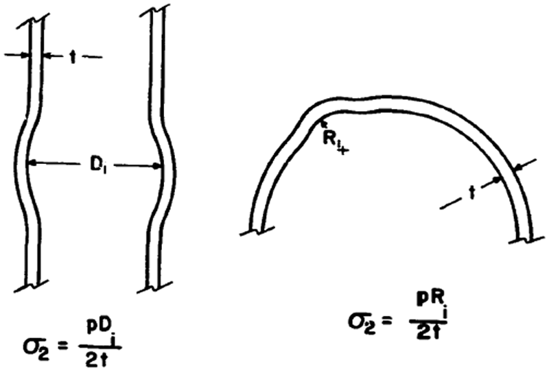
Necking of a thin-walled sphere under internal pressure. 71
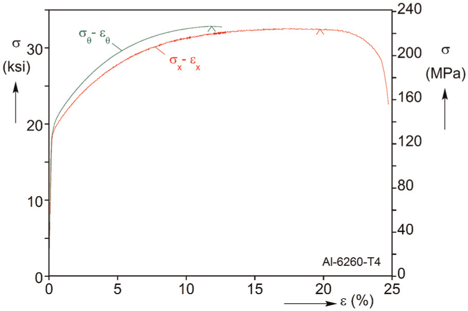
Difference between axial and hoop stress–strain responses of Al-6260-T4. 72
A further difference between THF and conventional sheet metal forming is that despite the thin-walled geometries involved, significant through-thickness stresses can develop during hydroforming in the regions of a workpiece that have expanded and have established contact with the surrounding die. This is because these regions are constricted between the internal pressure on the inside diameter and the stiff die on the outside one. Hence, the stress triaxiality, which is known to govern the failure process, can be markedly different from that in a stretched sheet or an inflated tube, which are oftentimes used to establish the applicable forming limits.
Finally, THF is generally more stable than many sheet forming processes with respect to localization and necking. In a stretched sheet, as soon as necking will lead to non-uniform thickness reduction, the stresses will be locally amplified, and thus, the deformation will localize and failure will occur. This is an inherently unstable system (material, geometry, loading). In contrast, a thickness undulation that will appear in a tube inflated inside a closed die can grow in a gradual and steady fashion, before it becomes unstable and triggers failure. As necking is a fully three-dimensional (3D) process and induces a triaxial stress field in its vicinity, failure data extracted from plane stress states are not precise measures of formability. 73
Tube inflation experiments
These peculiarities have led to the development of specialized testing techniques for assessing the material anisotropy and assessing the hydroforming limits of tubular materials (Figure 16). However, while these techniques are suited to tubular geometries, addressing the stress triaxiality and neck stabilization features of THF is generally not applicable. The ubiquitous experiment for characterizing anisotropy and hydroformability is the inflation of a thin-walled tube under axial load and internal pressure72,73,75–80 (Figure 16(a)). Typically, radial paths in the plane stress space are prescribed. However, the method is flexible enough to allow loading the material under much more complex, non-radial stress paths81,82 so that the path dependence of failure can be examined as well (Figure 17). This figure shows the stress and strain paths during radial and corner path experiments on anisotropic aluminum tubes. As expected, the strains show strong path dependence. The failure stresses are less sensitive to the path when the prestrain is low; however, they become more path-dependent at larger plastic strains, for the specific material examined.
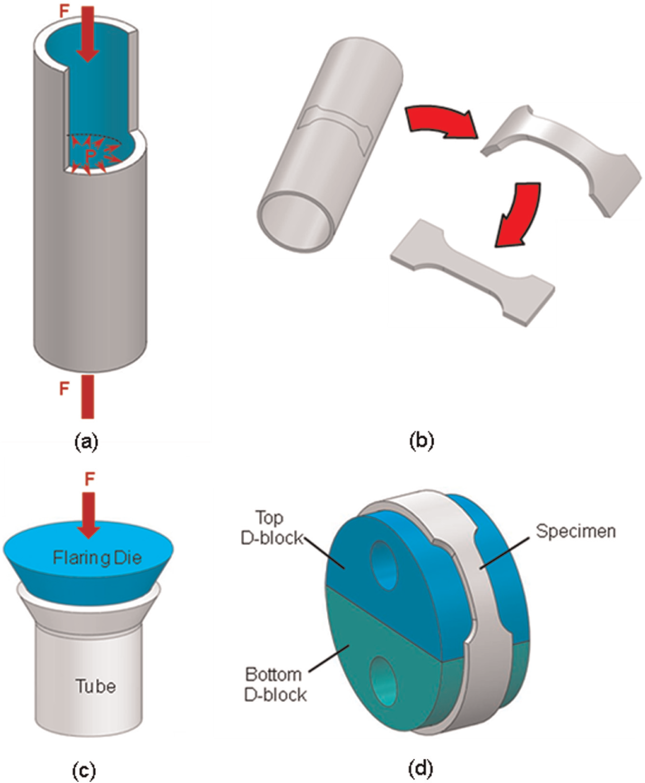
Testing methods for tubular specimens. 74 (a) Flattening and tension test, (b) tube flaring, (c) tube inflation under axial load and internal pressure and, (d) Ring Hoop Tension Test
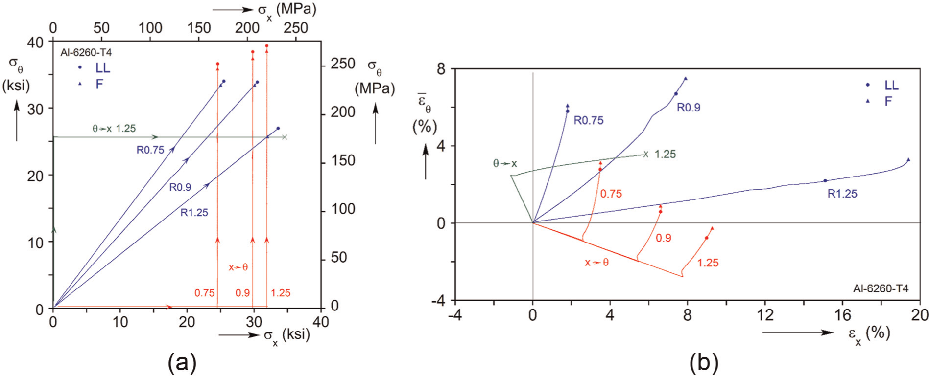
(a) Stress and (b) strain paths during the corner tension test of Al-6260-T4 tubes. 82
A disadvantage is that the equipment required for well-controlled experiments is complex. At the same time, only the first and part of the second quadrant of the plane stress space can be probed, while repeated loading and unloading, loading in the opposite direction and so on can be challenging. Kuwabara and colleagues76,77 are using sensors to control the true stress path in real time, while in other works72,73,79 the engineering stress path is prescribed, negating the need for real-time measurements of the deformed specimen geometry. In most experiments, the pressure is incremented until failure. However, Korkolis and Kyriakides72,73 opted to inflate the tubes under volume control, which allowed further deformation to develop, under decreasing pressure.
The tube inflation experiments are relatively complicated and require specialized equipment. One exception is the approach of Altan and colleagues83–85 who proposed a simpler free inflation experiment, with less control of the loading path (Figure 18). This technique can be used for routine assessment of tube properties, batch-to-batch variation and so on in the shop floor.
Tube formability test. 84
The method proposed in Li et al. 86 resembles the bulging of a sheet through elliptical dies. Recall that this is a way to deform the material along different loading paths. 87 In the experiment proposed in Daxner et al., 88 the tube is surrounded by a stiff die that has an elliptical opening. By varying the axes of the ellipse, various loading paths can be realized. The method can be used to assess the anisotropy in the plastic flow of the tube.
Other experimental methods
There are numerous efforts to develop simpler and quicker methods for evaluation of tube formability, without having to inflate the tube in a well-controlled manner. The simplest experiments to perform are as follows: (a) flattening of a ring that is then tested in tension as a strip (Figure 16(b)) and (b) flaring of the tube end (Figure 16(c)). The first case is described in the ASTM E-8 standard. However, since the flattening process induces an uncontrolled and uncertain amount of prestrain, this experiment is mainly used for qualitative comparisons between tube batches. It is also useful for testing the longitudinal weld of electrical resistance–welded (ERW) tubes. The flaring test is popular as it is easy to perform and it is assumed to replicate uniaxial tension in the hoop direction of the tube.88,89 However, the contact and friction between the tube and the flaring punch may oftentimes lead to multiple necking in the circumference of the tube. This indicates that the results from the flaring test should not be viewed as equivalent as those from a uniaxial tension test, where multiple necking is precluded and thus failure occurs soon after the first neck appears.
A simple technique to assess the plastic properties of the tube in the hoop direction is the Ring Hoop Tension Test (RHTT)74,90–92 (see Figure 16(d)). A ring is extracted from the tube stock and a gage section is machined on it. The ring is then placed on a pair of tight-fitting, well-lubricated D-shaped blocks, which are displaced with respect to each other on a universal testing machine. Since the gage section is positioned entirely on one of the blocks and the radius of curvature does not change during the test, no bending develops in the gage section. Recently, Dick and Korkolis 74 investigated the effect of contact stresses and friction on the measured response and found it comparable to the departure from plane stress of the usual free inflation experiment due to the internal fluid pressure. The RHTT lends itself to high-temperature testing, for example, for magnesium AZ31B. 92
Among other experiments that have been proposed, the Ring Tension Test 93 is explained, where a ring is pulled between two pins moving in opposite directions. The ring sides are gradually flattened until they become straight and then are deformed in tension until failure. This experiment is simple to perform, resembling the case described earlier and in the ASTM E-8 standard. As before, a disadvantage is that it is difficult to estimate the amount of prestrain that the straightening process involves. However, comparing the experiment to finite element analysis (FEA) as in Yoshimura et al., 93 a first estimate of the flow curve of the material and the bending prestrain can be achieved.
The growing popularity of warm- and hot-THF has created the need for testing at elevated temperatures. At this moment, the RHTT has been used successfully in this context. 92
As stated earlier, these testing techniques can yield useful information on the anisotropy and plastic flow of the material. Some can also yield useful information on the geometric effect on failure. However, none is suitable for replicating the stress triaxiality and the stable growth of a neck that is often encountered in THF. Therefore, it is recommended that after the careful determination of the plasticity/anisotropy and forming limits of the material with some of the tests described here and adopting these properties through suitably calibrated models in the finite element (FE) model of THF, this model is validated against a simple corner-filling hydroforming experiment 73 before being used to design the hydroforming of a complex part.
SHF
SHF process
SHF is a metal forming process that uses liquid media to form sheet metals. Typical SHF processes are illustrated in Figure 19. 94 In the SHF, a sheet workpiece is placed in the die cavity and clamped tightly. Then the pressurized fluid, instead of punch, deforms the sheet to the desired shape, as shown in Figure 19(a). Alternatively, the pressurized fluid can be used to push the workpiece onto the punch while the punch moves down, as shown in Figure 19(b).
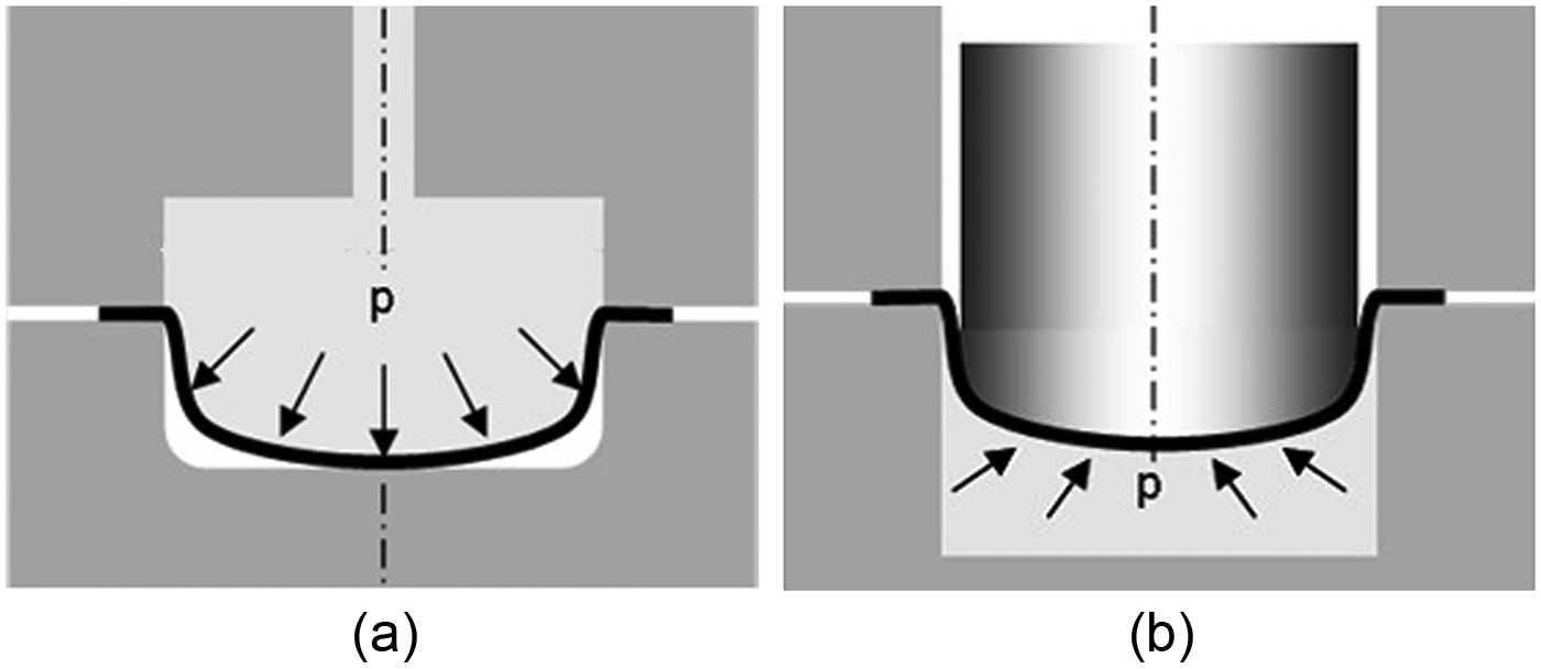
Schematic illustration of sheet hydroforming processes: (a) water punch hydroforming and (b) water die hydroforming. 94
The advantages of the SHF over the conventional stamping processes include higher drawing ratio, good surface finish, good dimensional stability, low tooling cost and less tool wear.95,96 The circular cup drawing example demonstrates the improved formability of SHF. 97 The circular cups produced by the stamping and SHF processes are compared in Figure 20. The cup height of 6.4 cm was achieved by the SHF conducted at room temperature, while the maximum cup height of 2.8 cm was obtained using the conventional stamping processes.
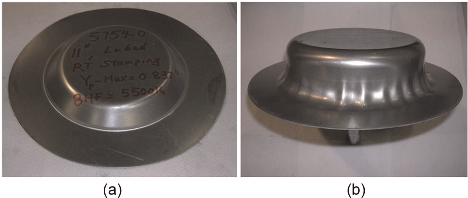
Circular cups produced by (a) stamping (height of 2.8 cm) and (b) sheet hydroforming (height of 6.4 cm). 97
Figure 21 shows examples of automotive parts manufactured by SHF.2,98 Contrary to the THF, SHF is mostly used for small batch production. The higher clamping force and high cycle time have limited its wider application in industry.
Recent R&D activities in SHF
Like THF, SHF has long been used as a major manufacturing process for producing sheet products that could not have been easily produced by conventional sheet stamping. In recent years, the productivity of SHF has been improved by introducing new ideas in the tooling and processes. SHF has become a promising technology for producing very thin sheet products. In this section, recent developments in SHF are outlined.
Novel SHF processes
Palumbo 99 proposed a novel approach for manufacturing an aluminum automotive component in a more flexible and less expensive process by combining the SHF process and rapid tooling technique. In his work, a layered die was created by assembling two-dimensional (2D) laser cut layers. The proposed approach, combining the hydroforming process with a rapid tooling technique, proved to be effective in rapidly manufacturing prototypes and thus in shortening the product design process.
Djavanroodi and Derogar 100 proposed a simplified SHF process using a floating disk. With a floating disk, as shown in Figure 22, two sides of a blank will suffer equal friction force due to the normal blank holding force. Therefore, the normal blank holding force and chamber pressure will be almost halved, resulting in the decreased punch force. The proposed floating disk method can simplify the tools used for hydroforming and can decrease the cost of the process.
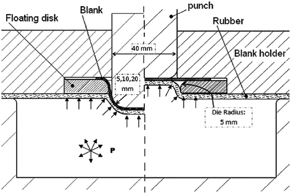
Hydroforming process assisted by a floating disk. 100
Warm SHF
Warm SHF is a promising process for aluminum alloys with low formability for realizing a high level of strain without fracture. Koç et al. 63 investigated the optimal process conditions of temperature, pressure and pressurization rate for maximum formability of AA5754-O of the warm SHF process. For simple stretch forming, the optimum process conditions were a temperature of 268 °C, a pressure of 25 MPa and a pressurization rate of 0.22 MPa/s, which provided the most balanced combination of uniform thickness strain with the greatest cavity fill ratio and sharpest radius.
SHF for thin sheets
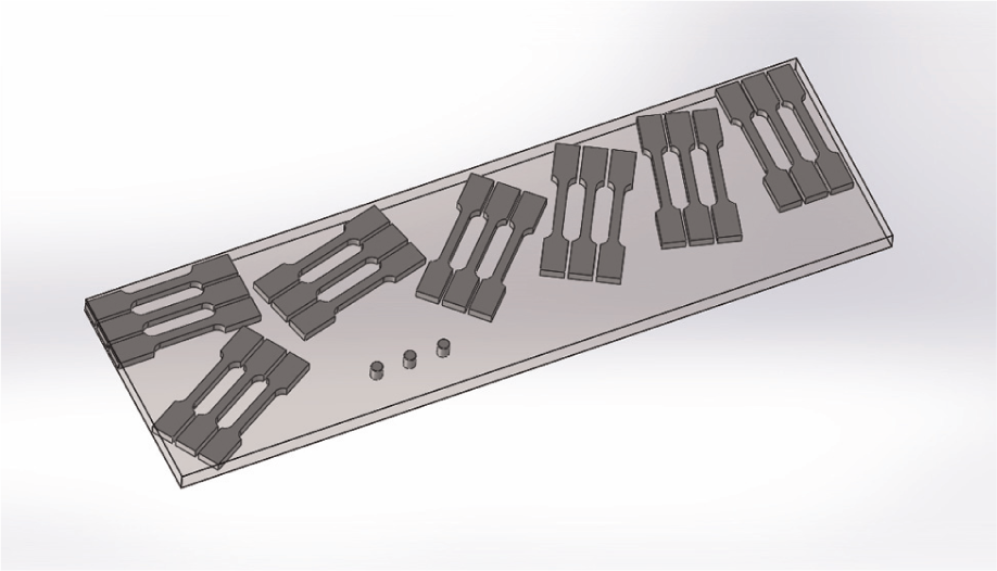
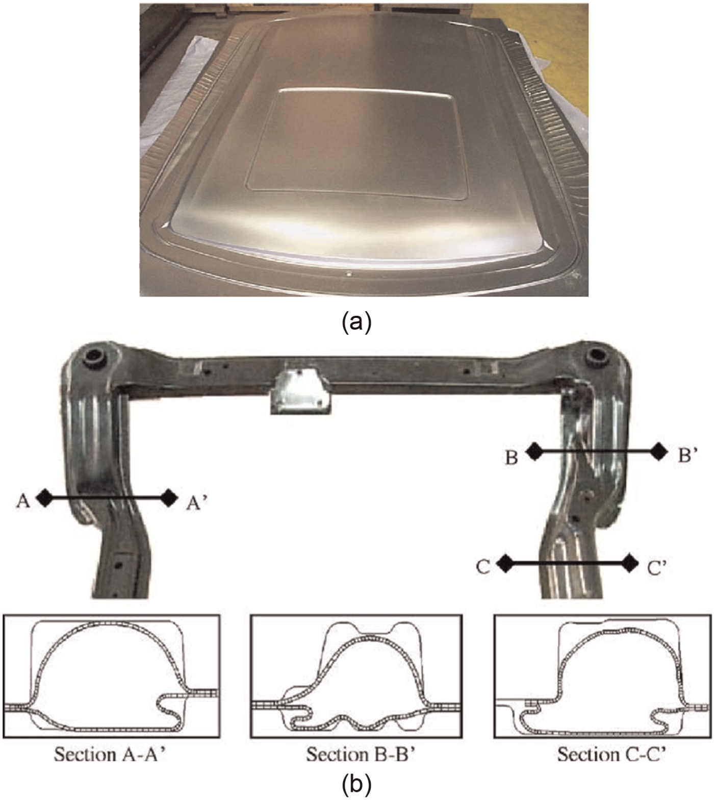
Recently, more attentions have been paid to the application of SHF to forming thin sheets for fuel cell bipolar plates. Bipolar plates in fuel cells carry fuel and air while conducting electric current and provide mechanical support for the stack. Because bipolar plates are pathways for gases, they are composed of many channels, as shown in Figure 23. 101 Due to their complex shapes, bipolar plates have been mainly manufactured by machining. Productivity and cost-effectiveness can be improved if sheet forming processes are used for manufacturing the bipolar plates. However, the sheet forming processes have not been widely used because of the limited formability of the conventional stamping processes.
Schematic drawing of a bipolar plate. 101
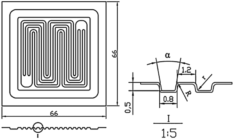
Mahabunphachai et al. 102 investigated the formability and surface roughness of metallic bipolar plates manufactured by stamping and SHF, as shown in Figure 24. They found that hydroforming produced bipolar plates with lower dimensional variations than the stamping. In addition, the hydroformed parts have a better surface condition than the stamped ones. Hung and Lin 103 manufactured the micro-flow channels for metallic bipolar plates by hydroforming, as shown in Figure 25. They achieved an aspect ratio of 0.468 at the hydrostatic pressure of 250 MPa using a specially designed HPH apparatus. The high aspect ratio of channels is expected to improve the overall performance of the fuel cell.
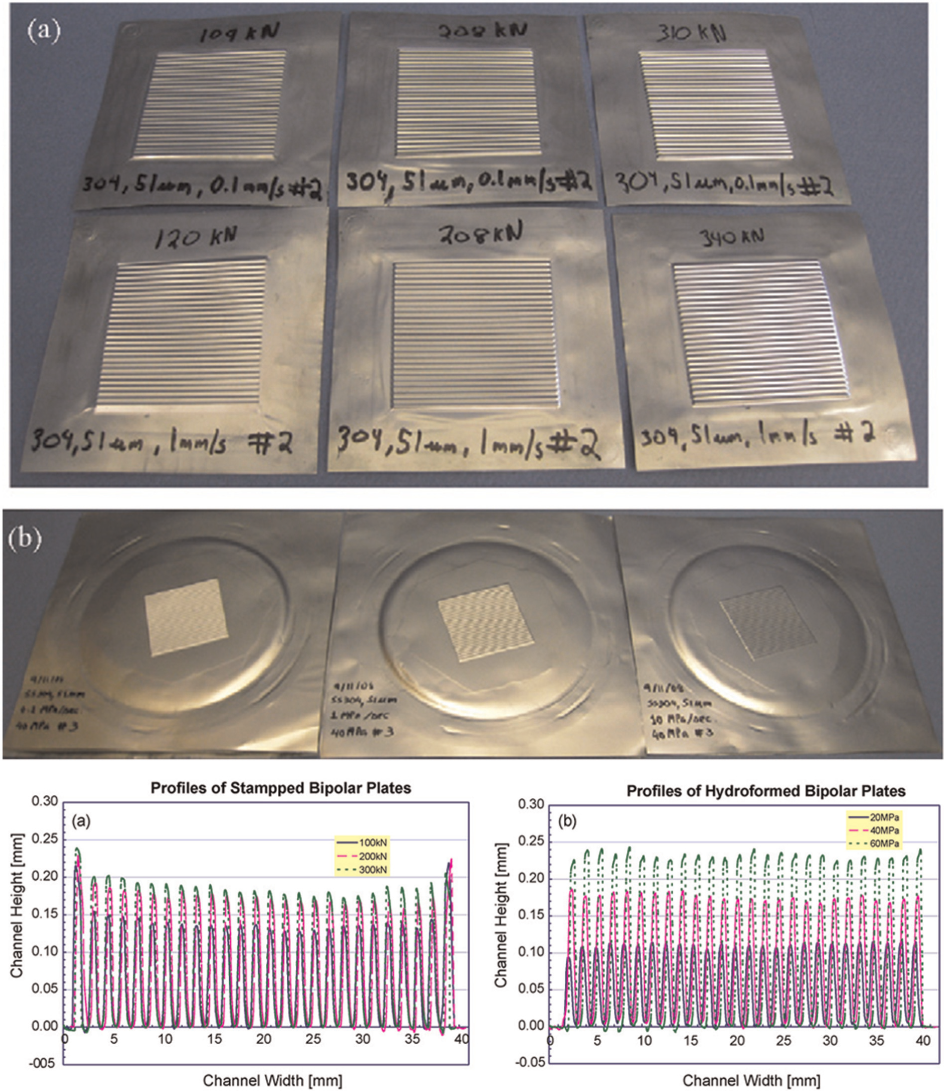
Comparison of (a) stamped and (b) hydroformed bipolar plates. 102 The graphs compare the laser measurement profiles of stamped and hydroformed specimens.
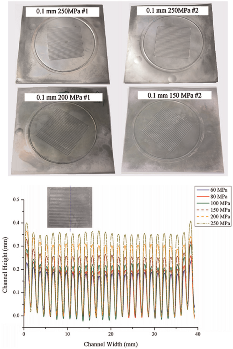
Hydroformed bipolar plate samples and the height profiles across the channels. 103
Computational modeling in hydroforming
Fundamental plasticity theory and analytical studies in hydroforming
Quite a few researches have been made to simplify the hydroforming process by introducing fundamental plasticity theory and simple geometry of hydroformed parts, which lead to the alternative to the complex FE modeling. The usual assumptions made in the analytical modeling of tube- or sheet-hydroforming analysis are as follows. First, the material is generally assumed to be homogeneous, isotropic and rate independent. Practically, the elasticity is ignored and simple hardening laws such as Swift or Voce type of flow stress are assumed. Of course, more sophisticated plasticity such as anisotropic yield function and kinematic hardening can be incorporated. Moreover, the effect of lateral pressure on the flow behavior of material is neglected. Second, the geometry is typically assumed to be circular or similar shapes that can be analytically expressed by polygons 104 (see Figure 26), and if necessary, the complex shape is sub-divided into several simplified pieces. The loading is subject to pressure, bending and/or unbending and the main strain to be analyzed is hoop strain. During the deformation, the strain is usually assumed to be constant through the sheet thickness and the stretch is the main deformation. Equilibrium of forces is enforced at each (sub) section to find analytical relations between radial stresses, hoop stresses and longitudinal stresses. For the frictional behavior between the tube or sheet and the tools, Coulomb’s friction law is assumed, as is often the case for general sheet metal forming modeling.
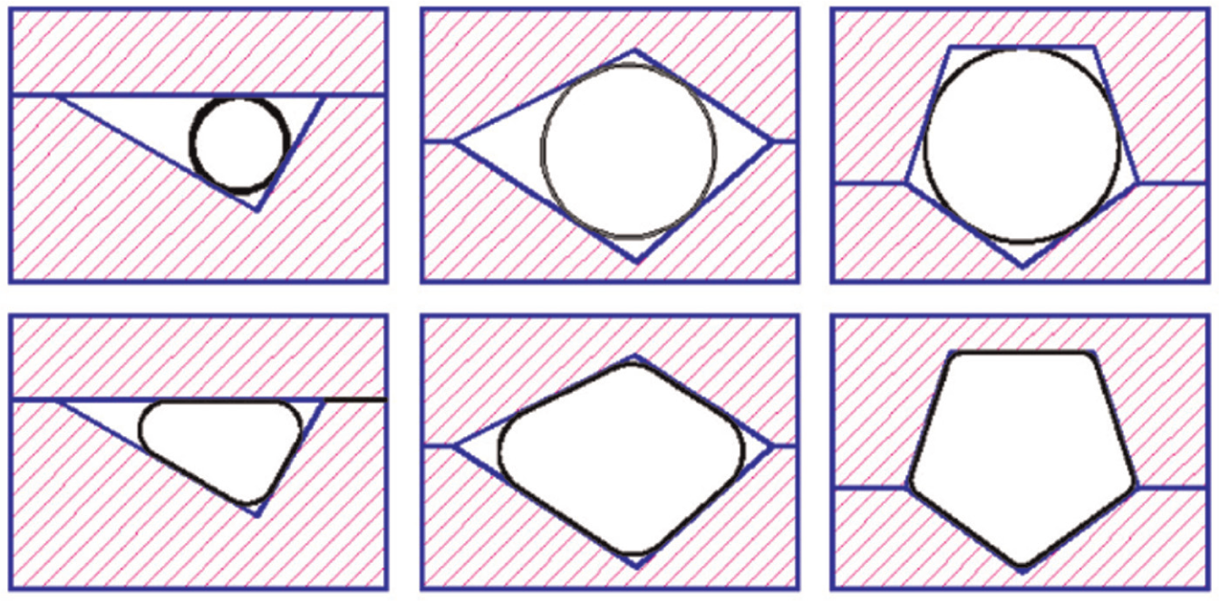
Family of polygon shapes used for the analytical modeling approach. 104
A good example for the analytical model of THF introducing most of the above features is the one by Yang and Ngaile. 104 They proposed an analytical model for planar THF, which is based on deformation theory. The model could predict the bending effects, local strain and stress distribution (see Figure 27) across the wall thickness and was successfully validated by comparing the results to the FEA and experiments on various irregular triangular, irregular quadrilateral and pentagonal hydroformed shapes.
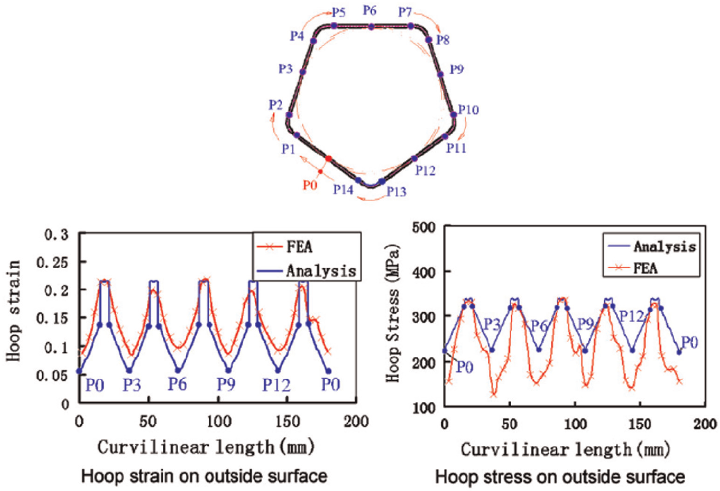
Strain and stress in the hoop direction and their comparison with FEM results. 104
The analytical model based on fundamental mechanics of the hydroforming process is particularly useful because the FE solution cannot provide efficient parametric study due to significant computational cost and time. On the other hand, the closed-formed or semi-closed form analytical models have been successfully used to study the optimal hydroforming process conditions efficiently but without sacrificing significant loss of accuracy. Recent work by Orban and Hu 105 proved usefulness of such parametric study in establishing guidelines for designing the structural THF process, especially in finding limits of the process capabilities.
Besides the above-mentioned examples, here are several examples that used the analytical approaches for the hydroforming analysis. Asnafi 8 derived relationships between parameters such as axial forces, yield strength, limiting strength and friction to the final shape and hydroformability. Xia 106 proposed an analytical model to predict failure and wrinkling for the circular tubes using internal pressure and end axial feeding. Also, similarly, Koç and Altan 107 predicted buckling, wrinkling and bursting failure in THF by applying plasticity, membrane and thin–thick walled tube theories. Besides these approaches, there are many other models that were used for the optimization of the hydroforming process parameters analytically.50,108–110
Constitutive models in hydroforming
Anisotropic yield function
The finite element method (FEM) as a numerical simulation tool has been widely used for the simulation of metal forming processes including hydroforming. In the FE simulations, the accuracy of the solutions highly depends on the constitutive models that describe the sheet metal behaviors under external loading. The simplest, but the most frequently used constitutive models in the hydroforming technology is the isotropic model. The isotropic model includes von Mises yield function and isotropic hardening under the classical elastic-plasticity scheme. The elastic behavior is also simplified as linear and isotropic. This simplified assumption has been well accepted when the material deformation in hydroforming is close to the proportional and the material itself behaves quasi-isotropically. Moreover, this isotropic constitutive model has been well adopted for the derivation of closed-form solutions or analytical models. The advantage of the isotropic assumption is that the experimental procedure is simple, and the uniaxial tensile test is usually enough.
However, as the demands for the lightweight materials in the automotive industry increase, more accurate constitutive models are necessary to account for the materials’ anisotropic behavior. Also, the forming complexity in today’s hydroforming technology is another reason why more complex constitutive laws are needed. Jansson et al. 111 optimized the THF process to reduce the possibility of tube bursting or wrinkling using FE simulations. Particularly, they adopted the two well-known anisotropic yield functions, Hill’s 112 1948 yield function which is popular among industrial users and Yld2000-2d criterion, 70 which has been proved as an effective yield function for the aluminum alloys. It was shown that the anisotropic behavior of the aluminum alloy AA6063-T4 could be satisfactorily predicted when the Yld2000-2d yield criterion was used. Figure 28 shows yield loci predicted by the Yld2000-2d for the AA6063-T4, and the FE model and prediction of pressure–radial displacement response are shown in Figure 29. The figure shows that the non-quadratic yield function Yld2000-2d perfectly predicted the response, while Hill model could not.
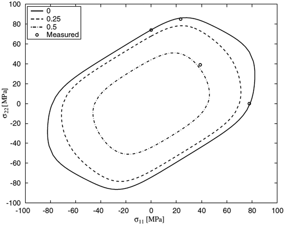
Aluminum alloy AA6063-T4 yield surface determined with eight parameters. 111
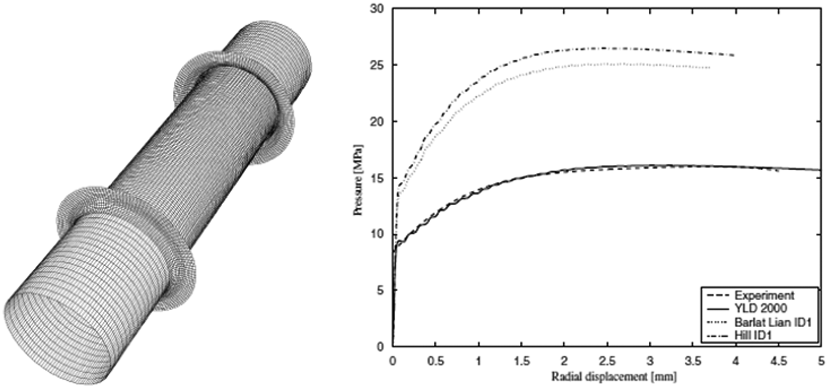
Predicted radial displacement–pressure curves by different yield criteria and their comparison with experiment. 111
The most challenging aspect when using the anisotropic yield function is to determine the anisotropy parameters. In particular, the Yld2000-2d model needs eight material parameters that can be characterized by the uniaxial tensile tests with three different directions and additional balanced biaxial tensile test.113,114 Especially, the latter is not conventional experimental procedure and needs special test equipment such as bulge test or disk compression test. A discussion of available experimental techniques was given earlier in this work.
More recently, Korkolis 5 carried out similar work to investigate the effect of anisotropic yield functions on the tube hydroformability. He considered three types of yield criteria: Hosford’s, 115 Karafillis and Boyce 116 (K–B) yield function and Yld2000-2d function. 70 The following are the major findings from the investigation. The initial yield surface could be fitted with good agreement using Hosford’s anisotropic yield function and two versions of the K–B yield function with exponents of eight. However, the best yield function was Yld2000-2d in terms of the accuracy fitting the experimental work contours. Plastic strains under the radial paths predicted by the Hosford’s and K–B models were not as good as that by the Yld2000-2d. The less accuracy resulted from the different predictability for the stress in the neighborhood of balanced biaxial tension state, in which the yield surface has the highest curvature. The simulated stresses associated with the limit load instabilities generally gave good agreement with the experiment within reasonable error. However, the corresponding strains at the onset of tube rupture were very sensitive to the anisotropic yield function adopted in the simulations. Among the three anisotropic yield functions, the Yld2000-2d was the best in predicting the onset of failure, as shown in Figure 30.
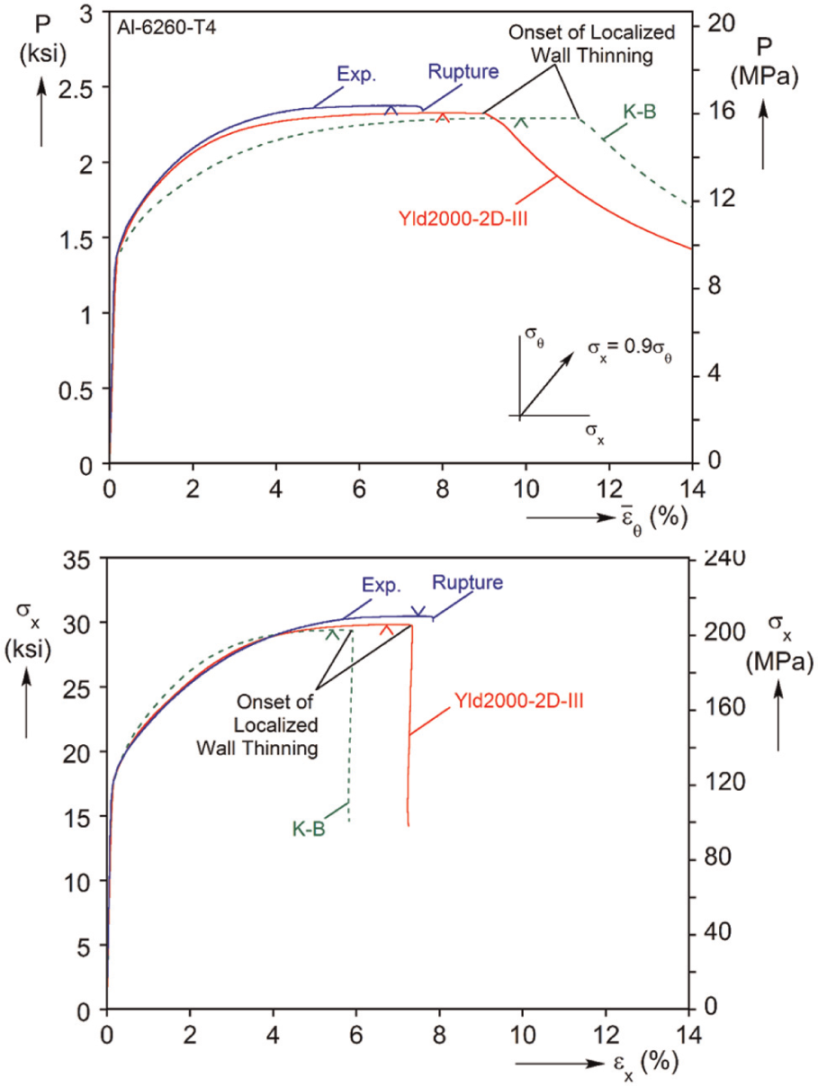
Results from numerical simulation of α = 0.9 path using two plasticity models and the corresponding experimental responses. 5
Kinematic hardening
In addition to the yield function, the hardening law that describes the evolution of the yield function is an important part of the constitutive modeling in the classical plasticity theory. Most of the metal forming simulations involve non-proportional deformation paths due to their complex structural component shapes and processes. In the hydroforming process, the deformation path can be sometimes proportional compared to the stamping process because the deformation mainly results from a fluid pressure inside the tube. Furthermore, unloading, which in stamping can lead to springback, is often not a concern. Hence, the isotropic hardening has been well accepted for the FE simulations. However, in the applications of the hydroformed parts, more advanced hardening models have been introduced. Especially, for the evaluation of the crashworthiness of the tube-hydroformed part, the kinematic hardening model was introduced to take the different material response under load reversal into account during the crash simulations. In Williams et al., 117 tubular parts were compressed during the hydroforming process which underwent reversed loading to tension when impacted. Thus, they studied the significance of the Bauschinger effect on the energy absorption during impact by introducing a combined isotropic–kinematic hardening model. Similarly, Lee et al. 118 compared the crashworthiness of the tube-hydroformed parts between isotropic hardening and kinematic hardening models. They concluded that the strain history during the hydroforming simulation should be included in order to accurately model the crash performance.
The necessity of the advanced material model such as the kinematic hardening law was also emphasized when the microstructure-based fracture model was incorporated to failure analysis during crash. 119 In this work, the main conclusion is that material anisotropy, kinematic hardening and through-thickness stress effects during the hydroforming operation should be included during the hydroforming simulations.
Through-thickness stress
The deformation in the hydroforming process is frequently regarded as a plane stress state for the efficiency of the FE simulations. However, it is reported that considerable through-thickness normal stress may arise on both sides of the sheet metal when the pressure is at very high level, that is, 200–300 MPa.52,120 This through-thickness stress component might have significant influence on the formability. Therefore, more effort needs to be paid to account for the effect of the normal stress, which requires the characterization of the flow stress curve in the normal direction, 3D yield criterion and pressure-dependent forming limit model. 121
Strength differential material model
Most of the cubic materials such as steels and aluminum alloys represent symmetric plastic flow behavior; that is, the tensile and compressive behaviors are usually the same. However, many hexagonal close-packed (HCP) crystals represent significant asymmetric flow behavior, which has been reported in the literature and is attributed to the different deformation mechanisms between tension and compression (dislocation slip and twinning-driven mechanisms, respectively). Despite this complication, Mg or Ti alloys offer great potential for lightweight, hydroformed components by replacing common materials such as steels due to their low density. 122
The challenge for the successful application of the Mg alloys is the limited formability at room temperature, which leads to the introduction of forming at elevated temperature range, around 200 °C–300 °C. This has been explained by the limited slip activity at lower temperature, while the activation of the additional slip systems increases as the temperature increases.65,123–127 Although the low formability of lightweight alloys could be compensated by increasing temperature, a more economical manufacturing process needs to be developed to optimize the temperature and other forming conditions. For this purpose, the forming process for Mg alloy sheets has been optimized using FE simulations that require accurate material constitutive models. Particularly, the model should reproduce the temperature-dependent plastic flow; that is, the model should cover the flow behavior from room temperature to the temperature around 200 °C. However, to date, most of the FE simulations for the forming process of Mg alloys employed classical isotropic material models such as the von Mises yield function and a temperature-dependent isotropic hardening model that cannot explain the asymmetric flow behavior.128–130 A major prediction of the simulations to date is the forming force during the isothermal forming at high temperature, which resulted in reasonably good agreement to the experiments.
Recently, efforts to develop efficient phenomenological constitutive models that consider the asymmetric flow behavior at room temperature and symmetric-like behavior at increased temperature increases have been made by several authors. They successfully predicted the flow stress–strain curves at room temperature and the springback of draw-bent Mg alloy sheet at room temperature. Kim et al. 127 proposed a two-yield surface model that takes into account the twinning and slip activations and could predict the flow stress–strain behaviors at a variety of temperature ranges. These advanced constitutive models might not be very useful for typical hydroforming process since the deformation at this process is almost proportional, but they will be very useful for the application of tube-hydroformed parts for the post-processing such as bending and crashworthiness. Of course, the importance of the advanced models might be significant for the SHF, where the deformation path is basically non-proportional and temperature dependent as well.
Strain rate sensitivity
The sheet metal forming processes including hydroforming for the manufacture of complex parts are generally performed in the quasi-static to intermediate strain rate ranges. In addition, when the warm forming process is employed for the forming of lightweight alloys to increase the formability, the strain rate becomes more important. For example, previous researches have shown the strain rate dependence of lightweight alloys at elevated temperature. 153 The simplest viscoplastic model that describes the flow behavior as a function of strain rate is the multiplicative Swift law as follows

where

The above model was incorporated to simulate a temperature-dependent anisotropic material behavior during the hydroforming process for two aluminum alloys: AA5182-O and AA5754-O. A fully coupled thermo-mechanical FEA was performed for the temperature range from 25 °C to 260 °C under various strain rates. Simulation results gave very good agreement with experimental data at several temperatures in terms of both forming behavior and locations of failure. From this investigation that used an advanced FE procedure, it was found that it is preferable to maintain the lower temperature of the punch instead of a uniformly high temperature for all tools, for maximum formability.
Crystal plasticity analysis
Crystal plasticity incorporated into the FE method, or the so-called CP-FEM, has attracted a lot of attention since it takes into account the microstructural feature of plasticity in grain scale, that is, the plasticity is detailed by the slip activities of dislocations on the prescribed slip systems. The CP-FEM (or even other type of CP approach) has been successfully applied in predicting the polycrystalline texture analysis, fracture or forming limit diagram, fatigue and so on. The detailed constitutive description for the CP is out of the scope of this work, but the main idea is that the plastic strain rate is assumed to be the sum of shear strain activated on each slip system. And, the stress is calculated by the lattice distortion or rotation induced by the elastic part of the deformation gradient, decoupled from the total prescribed deformation gradient.137–139
The application of CP-FEM to the hydroforming process has not been very popular due to its computational cost and efficiency. Recently, Zamiri et al. 140 and Guan et al. 141 utilized the CP-FEM for the investigation of THF processes. Their polycrystalline model was implemented into the commercial software ABAQUS and could provide a good alternative to the phenomenological anisotropic model in predicting the response of the extruded tube under different loading conditions. The model could calculate the evolution of crystallographic texture under the hydroforming process of the extruded aluminum tube. The predicted strain distributions after hydroforming gave a better agreement than the result by the phenomenological anisotropic yield function compared to the experimentally measured strains (see Figure 31).
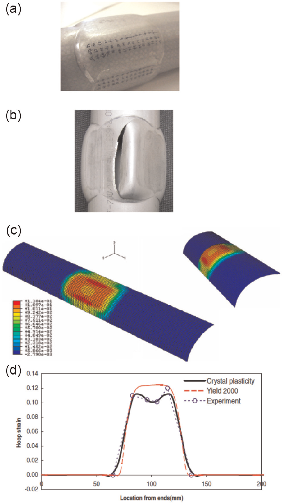
The application of crystal plasticity to tube hydroforming: (a) the corner area of the hydroformed tube, (b) the location of fracture at higher pressure, (c) hoop strain distribution and location of strain localization obtained by crystal plasticity model, and (d) experimental and numerically predicted hoop strain distribution along the length of the hydroformed tube.
The CP-FEM approach was also utilized with better performance than the classical phenomenological models for the micro-hydroforming process because the number of grains has larger influence on the deformation behavior than that of the conventional macro-level hydroforming. In other words, the number of grains on the micro-parts is sometimes much less than 10, so the deformation can be non-homogeneous unlike the macro-level case. Due to this reason, the CP approach can be very appropriate, because this model can relate the plastic behavior to the microstructural aspect of the micro-hydroforming part. Zhuang et al. 142 successfully utilized the CP-FEM approach to capture the localized thinning of microtube hydroformed parts with different microstructures. They concluded that the localized thinning in the hydroforming of micro-level tubes is greatly influenced by the microstructure and grain orientations, which is not possible by the classical elastic-plasticity approach with yield function concept.
Strain path effect in computational modeling for hydroforming
Recent investigation by Korkolis and Kyriakides 82 presented experimental observations of significant dependency of the formability of Al alloy tubes on the strain path. They devised a novel experimental procedure to examine the effect of the loading path under combined internal pressure and axial load for Al-6260-T4 tubes. Two types of the loading paths were tested, that is, orthogonal stress path and radial stress path. They confirmed that for that material, the failure strains have significant path dependency as shown in Figure 32. The comparisons of failed specimens clearly show that the amount of circumferential strain (Figure 32(a)) and the type of failure (Figure 32(b)) depend on the applied loading paths.
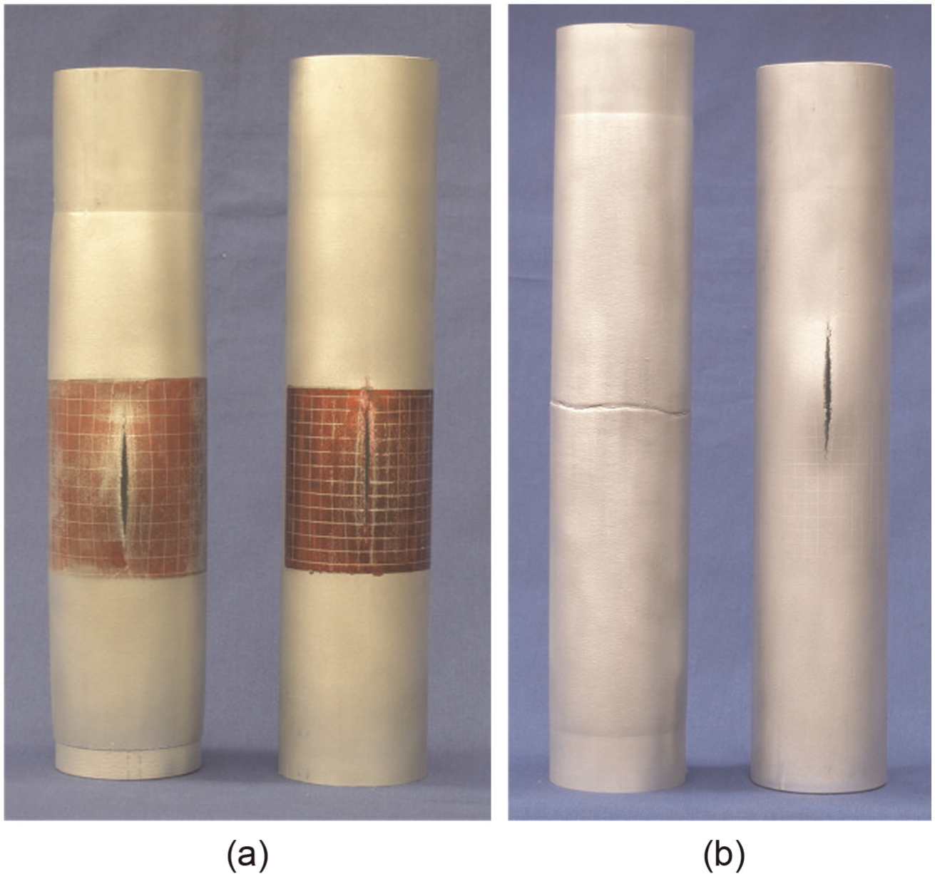
Comparison of failed test specimens: (a) for R0.75 (LHS) and x → θ 0.75 (RHS) and (b) for R1.25 (LHS) and for the corresponding corner path x → θ 1.25 (RHS). 82
In the FE modeling to evaluate the rupture in the THF process under strain path changes, the anisotropic yield function Yld2000-2d was applied in Korkolis and Kyriakides. 82 Although there is a little discrepancy with the failure strain, the predicted failure stress reproduced quite well the measured one. The deviation from the experiment might be due to the isotropic hardening model that cannot explain the complex loading path changes such as orthogonal and reverse loading changes.
In general, sheet metals undergo complex strain path changes during real forming processes. The custom isotropic hardening model assumes the linear strain path, thus cannot describe an accurate description of the material behavior in real forming simulations. Another type of constitutive model incorporating translation of the yield surface, or the kinematic hardening, can reproduce the plastic behavior for materials subjected to load reversals, which is often characterized by the Bauschinger effect.143–145 Because the classical kinematic hardening models cannot reproduce the material response under cross-loading, more advanced constitutive models were needed to explain the complex realistic experimental observations under strain path changes such as orthogonal and cross-loading conditions. 146 The model proposed by Teodosiu and Hu147,148 and recently proposed homogeneous yield function-based anisotropic hardening (HAH)149,150 could successfully capture the complex behavior of sheets during strain path changes. The latter could reproduce the strain–stress curves under continuous loading path change from tension to shear, as shown in Figure 33. 151 The deformation path in the THF is very complex because of the various control methods of internal pressure and axial forces. Therefore, to predict the deformation response of the tube during hydroforming, and in particular in assessing the formability, more accurate constitutive description might be essential.
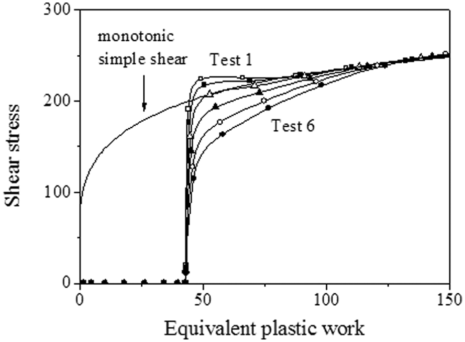
Simulation results for shear stress after tensile test with different transient rates. 151
Conclusion and outlook
Hydroforming is a well-established and yet still developing technology in automotive and other manufacturing industries. In this article, the general principles and recent research activities of the hydroforming technology were reviewed. For THF, recent major developments are described as an indication of future trends. The process design strategies for the large expansion ratios with minimum wrinkling were discussed. The pulsed THF method was introduced as another way of enhancing the hydroformability. And the processes utilizing the enhanced ductility of metals under high hydrostatic pressure were presented. The difficulties in obtaining material properties of tubular form were discussed, and the specialized testing techniques for assessing the material anisotropy and assessing the hydroforming limits of tubular materials were reviewed. For SHF, few applications have been reported in conventional automotive industries because of its high cycle time. However, the SHF is expected to be a promising technology for future vehicles with fuel cells. The analytical and numerical modeling efforts for the hydroforming processes were reviewed. In order to cope with recent trends in lightweight automotive design, the hydroforming technology will be applied to the emerging materials such as AHSS, magnesium alloys and other materials with high specific strength. In order to make successful implementation of the hydroforming technology with the newly generated advanced materials, the conventional processes need to be further optimized or improved considering the nature of the deformation mechanism of individual material. For example, the deformation mechanism of the magnesium alloys is quite different from ferrous and aluminum alloys due to the combined effect of deformation twinning and slip. Therefore, accurate characterization of the materials for hydroforming should precede the material modeling and the computational implementation. The recent constitutive models for the emerging materials used in hydroforming were also discussed from the anisotropic yield functions, the hardening equations, to the CP. These models will be very useful tools to find new opportunities of the hydroforming technology. Especially, the constitutive models capturing the complex strain path changes during hydroforming should be further investigated for future applications of the hydroforming technology to produce parts with more complicated shapes.
Footnotes
Declaration of conflicting interests
The authors declare that there is no conflict of interest.
Funding
This work was supported by the National Research Foundation of Korea (NRF) grant funded by the Korea government (MSIP) (no. 2012R1A5A1048294). Y.K. acknowledges the support of the US National Science Foundation through grant CMMI-1031169.