
Abstract
Multi-axis plunge milling has an increasing application in the manufacturing industry to rough machine open blisks. Its objective is to remove mass stock material with high efficiency and machining stability. In multi-axis plunge milling, cutting parameters are usually determined conservatively as constants to prevent excessive cutting forces and unexpected tool breakage. This is an obstacle to improve the cutting efficiency of rough machining. To address this issue, this article proposes an original approach to schedule the feedrate in multi-axis plunge milling of open blisks based on material removal rate. The material removal rate in plunge milling is directly proportional to the area of the cross section on the removed stock material. According to different types of the cross section, one feeding phase in plunge milling of open blisks is divided into three feeding stages. The cross section in each feeding stage is then identified with a mathematic and geometric method. Its area is then calculated by its constituting elements, such as a polygon, circular arches, and elliptical arches. After that, the feedrate is regulated to guarantee a constant material removal rate in the entire feeding phase. Experimental tests are conducted to verify the proposed feedrate scheduling method. This approach can reduce the cutting time and smooth the variances of cutting forces and torque in multi-axis plunge milling of open blisks.
Keywords
Introduction
Blisks are key parts of the rotating portion of a fan or compressor stage of a jet engine. They are designed as one-piece units by joining rotor disks and blades together instead of traditional usage of the dovetail attachment. This integrated structure reduces the engine’s part count, weight, and aerodynamic losses. 1 When machining an open blisk, 90% of stock material is approximately removed from a forged blank in roughing process. It is of great importance to plan roughing process efficiently with appropriate cutting strategies to reduce the cycle time. Multi-axis plunge milling is widely adopted in the manufacturing industry to rough machine open blisks. In plunge milling process, a cutter feeds along the tool axis direction and removes material with its bottom edge. Taking advantage of high rigidity of the cutter in the feeding direction, plunge milling performs higher stability than conventional side milling and plane milling. Current researches about plunge milling of blisks mainly focus on tool path planning. Ren et al.2,3 planned tool orientations and locations (called plunger paths) with a minimum area criterion in multi-axis plunge milling of blisks. Li et al. 4 calculated plunger paths of open blisks with the least-square method to pursue a uniformly distributed machining allowance. Liang et al. 5 optimized the plunger paths in four-axis plunge milling of open blisks to minimize the residual material on the blades. These researches provide effective approaches to obtain tool paths for multi-axis plunge milling of blisks. However, the efficiency improvement for plunge milling is not involved.
Two directions are mainly concerned to improve the cutting efficiency of plunge milling. One direction is optimizing the plunger selection to reduce the cutting time. Considering that a larger plunger can remove more stock materials than a smaller one, the principle of this approach is to adopt as large plungers as possible to machine the workpiece. The overlapped circles filling (Ocfill) method6,7 and the maximum hole degree (MHD) theory 8 are popular methods to optimize the circle packing problem in plunge milling of a pocket. The largest available plunger is planned to fill the pocket without overlapping first, and then other plungers are used to cover the unoccupied areas gradually in a sequence of the plunger diameter. Han et al. 9 proposed another plunger selection method in consideration of the interference checking in multi-axis plunge milling. The other direction to improve the cutting efficiency is adopting appropriate cutting parameters to reduce cutting forces and chatter vibrations.10–12 In this approach, time-domain models of plunge milling are usually established to predict the stability lobes, with which larger cutting parameters can be used in plunge milling without chatter vibrations.
These two directions improve the efficiency of plunge milling in consideration of the geometric and dynamics issues. However, the cutting parameters in these researches are constants, which might not be efficient for multi-axis plunge milling. The stock material removed in one feeding phase is varying with the feeding depth in multi-axis plunge milling due to the different tool orientations. A traditional approach is to set the cutting parameters as conservative constants. These constants are usually determined by the maximum cutting load in the feeding phase in order to prevent excessive cutting forces and unexpected tool breakage. However, they will reduce the cutting efficiency in other feeding phase. Consequently, real-time cutting parameters are required to adapt the variance of cutting load in multi-axis plunge milling. From a literature review, feedrate scheduling is a popular approach to regulate the cutting load in unit time, which will be effective to improve the cutting efficiency in multi-axis plunge milling.
Feedrate scheduling is usually conducted based on cutting force models or material removal rate (MRR) models. 13 Guzel and Lazoglu 14 presented a mechanics-based feedrate scheduling method for ball-end milling of sculpture surfaces. Ko and Cho 15 regulated feedrate for three-dimensional (3D) ball-end milling with the referenced cutting force calculated with transverse rupture strength of the cutter. Kim et al. 16 proposed a mechanistic cutting force model to adjust the feedrate for indexable end milling. Li et al. 17 calculated average power from the MRR and optimized feedrate according to an empirical cutting force predicted from this average power. Benardos and Vosniakos 18 regulated feedrate and cutting speed with the cutting force computed by the artificial neural networks (ANNs). Erdim et al. 19 compared force-based and MRR-based feedrate scheduling strategies theoretically and experimentally for ball-end milling of free-form surfaces. The results showed that the mechanistic feedrate strategy is more meaningful in terms of cutting forces compared with the geometric one. However, the experimental results of force-based feedrate scheduling rely on the accuracy of the cutting force models. In addition, plenty of additional cutting experiments are essential to calibrate and verify these force models, which will take a longer time before the real machining process. By contrast, it is necessary to use MRR-based feedrate scheduling for rough machining due to the simpler process and shorter calculation time. 13 The MRR-based feedrate scheduling strategy regulates feedrate by minimizing the variances of the MRR in the cutting process. Ip et al. 20 proposed a fuzzy-based MRR optimization approach by adjusting the cutting feedrate to compensate the variance of cutting speed. Jang et al. 21 developed a voxel-based MRR model to represent the state of in-process workpiece and applied this model to regulate feedrate. Baek and Ko 22 compared two MRR-based feedrate scheduling strategies in machining a free-form surface. The experiments demonstrated that the resultant force with the feedrate scheduling based on chip volume per tooth is closer to the desired chip load than that based on chip volume per numerical control (NC) block. These researches provided effective MRR-based feedrate scheduling solutions for conventional milling with a ball-end mill or an indexable end mill. The research on feedrate scheduling for plunge milling has not been retrieved. Therefore, it is necessary to conduct related research to reduce the cycle time in multi-axis plunge milling.
This article presents an MRR-based feedrate scheduling strategy for multi-axis plunge milling of open blisks. When a cutter feeds in the tool axis direction, the contacting area of cutter bottom and uncut material varies with the feeding depth. This contacting area is also the cross section of the removed material perpendicular to the current tool axis direction. The MRR in plunge milling is directly proportional to the feedrate and the area of this cross section. Therefore, to obtain a constant MRR, the scheduled feedrate should have an inverse relationship to the cross-sectional area. In this article, the feeding phase in plunge milling of open blisks is divided into three feeding stages mathematically. Then, the cross section in each feeding stage is identified and calculated to schedule the feedrate. Experimental tests are conducted at last to verify the proposed feedrate scheduling method.
Division of the feeding phase
Figure 1 shows the plunge milling process to machine an open blisk. In this figure, the cutter on one plunger path is shown as a cylinder. Because previous plunger paths have removed a part of the stock material, the material removed by the current discussed plunger path has an irregular shape, as shown in Figure 2. Before identifying the cross section and calculating its area, each feeding phase of plunge milling process is divided into three feeding stages in this section according to the composing types of the cross sections.
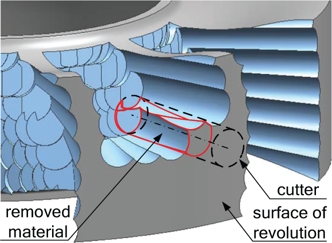
Plunge milling process to machine an open blisk.
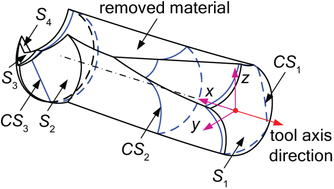
Cross section on the removed material.
The first feeding stage starts when the cutter cuts the surface of revolution of the blank (called the surface of revolution briefly in this article, shown as S1 in Figure 2) and ends when the cutter bottom just completely immerses into the blank. The second feeding stage follows the first one and ends before the cutter cuts the cutter bottoms of previous plunger paths, which are shown as surfaces S2–S4. The others of the feeding phase belong to the third feeding stage.
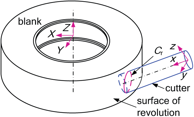
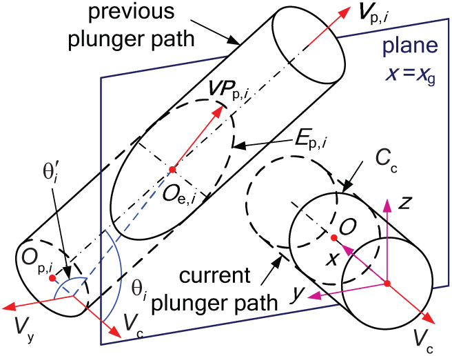
To calculate the dividing points of the feeding stages, a cutter coordinate system and a part coordinate system are introduced as xyz and XYZ coordinate systems (or frames), respectively, as shown in Figure 3. The x-axis is the feeding direction, while the y-axis is perpendicular to the x-axis and the axis of revolution of the part. Then z-axis is determined by the x-axis and the y-axis according to the right-hand rule. The origin of the xyz frame is located at the start point of the feeding phase on the cutter axis. The Y-axis is the same as the y-axis, while the Z-axis is the axis of revolution of the part. Then the X-axis is determined by the Y-axis and the Z-axis according to the right-hand rule. The origin of the XYZ frame is on the axis of revolution of the part, with the same Z value as the origin of the xyz frame. It is worth pointing out that the coordinate systems shown in Figure 3 just present the axis directions, in which the origins are not exactly located at the specified points for a clear demonstration.
Calculation of the intersection curve Cr.
Suppose the origin of the xyz frame and the unit vector of the x-axis in the XYZ coordinate system are
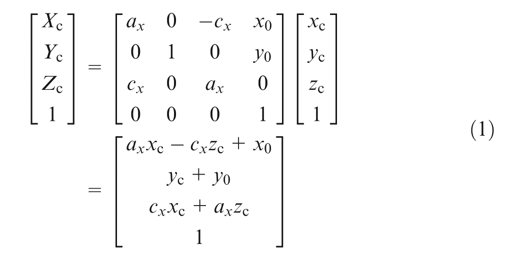
Suppose the rotating radius and Z value of the surface of revolution in the XYZ frame are
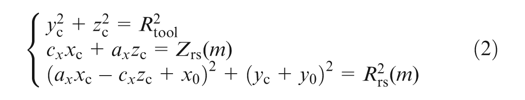
Equation (2) can be written as
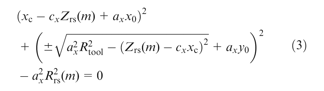
In equation (3), ax, cx, x0, y0, and Rtool are constants. Then xc is a function of parameter m, which can be written as xc(m). The x value of the dividing point of the first and the second feeding stages is calculated as
The x value of the dividing point of the second and the third feeding stages, denoted as x23, is related to tool orientations and locations of the previous plunger paths. Denote the tool orientation of the ith previous plunger path as a unit vector

Consequently, the feeding phase of the current plunger path is divided into three feeding stages in the feeding direction as: (a) the first feeding stage:
Identification of cross section
When intersecting the cutter with a plane perpendicular to the current tool axis, the cross section on the current plunger path is a circle, while those on previous paths are ellipses. In this article, these two kinds of cross sections are called “current circle” and “previous ellipses” for convenience, respectively. The current circle is a circle located at the x-axis with the radius of Rtool. In this section, the defining parameters of previous ellipses will be calculated first. Then the cross section will be determined in the second feeding stage. After that, the determination of cross section in the third and first feeding stages will be introduced based on that in the second feeding stage.
Calculation of ellipse parameters
A previous ellipse can be determined by its defining parameters, which are center point location, inclined angle, major radius, and minor radius. The tool axis direction of the current plunger path is

Calculation of previous ellipse.
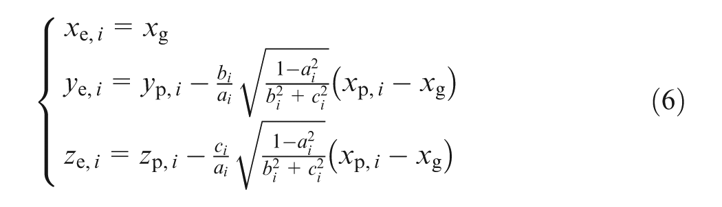
The ideal cross section of this previous plunger path on plane x = xg is an ellipse, denoted as ellipse Ep,i. The center point

Determination of the cross section in the second feeding stage
The cross section in the second feeding stage is determined only by the current circle and previous ellipses, as circle CC and ellipses E1–E8 shown in Figure 5. In this figure, ellipses E1–E6 are related to forming the cross section by intersecting the current circle, called related previous ellipses. The cross section of the removed material is the zone that is neither outside the current circle nor inside the related previous ellipses. It can be determined as follows.
Cross section in the second feeding stage.
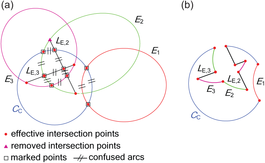
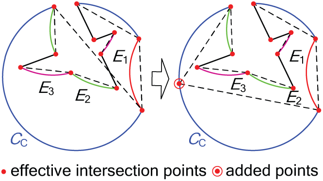
First, decompose the circle and ellipses into several arcs by their intersection points. Each circular/elliptical arc is defined with its two endpoints and its parent circle/ellipse. Second, reserve all effective intersection points. They are neither outside the circle nor inside the ellipses, as shown in Figure 6(a). Third, keep the arcs whose two endpoints are effective intersection points and remove the others, as shown in Figure 6(b). Fourth, mark the intersection points on the ellipse that intersects only the current circle. Set an arbitrary inner point as a sample point on each confused arc whose two endpoints are marked. The confused arcs with sample points satisfying the condition proposed in the second step are reserved. All left arcs compose the cross section in the second feeding stage, shown as effective arcs and reserved confused arcs in Figure 6(b).
Determination of cross section in the second feeding stage: (a) recognizing effective intersection points and (b) dealing with a confused situation.
Determination of the cross section in the third feeding stage
In the third feeding stage, the cutter cuts the machined surface left by the cutter bottom of one or more than one previous plunger path. The cross section in this feeding stage is different from that of the second feeding stage by adding one or more than one elliptical arch, shown as line
Elliptical arch on the cross section of the third feeding stage.
Figure 8 shows the process to determine the cross section in the third feeding stage. In this figure, ellipse E1 is a complete ellipse, while ellipses E2 and E3 are cut off to be elliptical arches by lines LE,2 and LE,3, respectively. The determining process is similar to that introduced in the second feeding stage by replacing ellipses with elliptical arches where applicable. The determined cross section is shown in Figure 8(b).
Determination of cross section in the third feeding stage: (a) determining process and (b) determined cross section.
Determination of the cross section in the first feeding stage
The cross section in the first feeding stage can be initially determined as the second feeding stage. In this feeding stage, the cutter cuts the surface of revolution on curve
Determination of cross section in the first feeding stage.
MRR calculation and feedrate scheduling
Area calculation of the cross section
An accurate area calculation of the cross section in the second feeding stage will be introduced first and then the third and the first feeding stages. The cross section in the second feeding stage is decomposed into circular and elliptic arcs by all effective intersection points P1–P9, as shown in Figure 10. Connect points P1–P9 with lines to form a closed polygon. Each circular arc and its related line constitute a circular arch, while each elliptical arc and its related line form an elliptical arch.
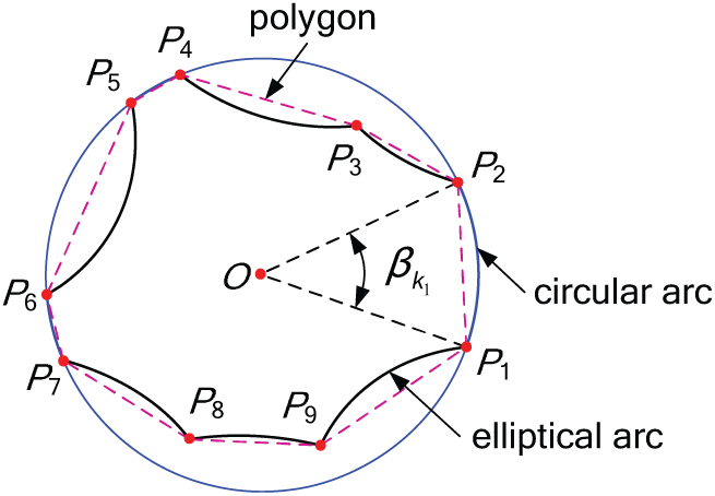
Decomposition of cross section in the second feeding stage.
Suppose the numbers of circular and elliptical arcs are N1 and N2, respectively, while the number of the intersection points is N = N1 + N2. Denote the kth intersection point as
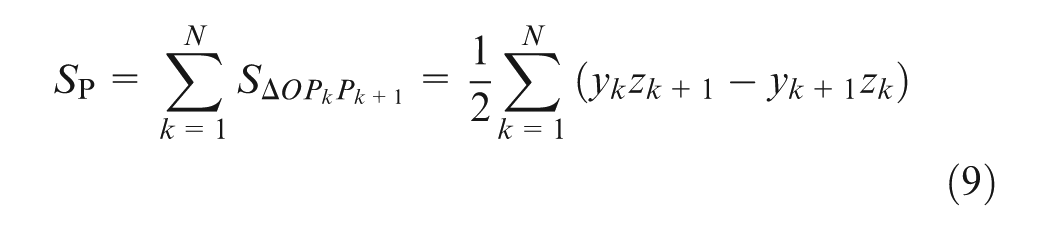
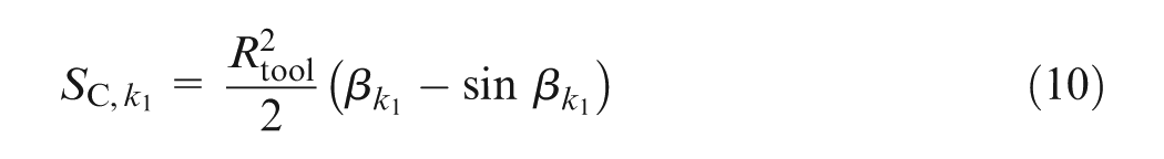
As shown in Figure 10, the area of the k1th circular arch
As shown in Figure 11, an ellipse can be converted from a circle by expanding the circle radius Rtool in one axis direction to the major radius
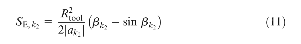
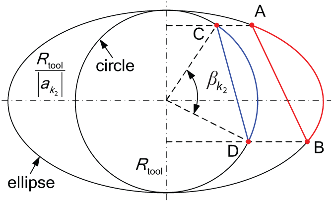
Area calculation of an elliptical arch.
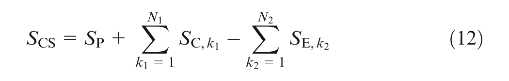
Therefore, the area of the cross section SCS is equal to the area of the polygon plus all circular arches and then minus all elliptical arches
When the cross section contains more than one connected region, as shown in Figure 12, calculate area of each separate region and add them up. Even though no polygon can be constituted with two points (N = 2) in Region 1 of this cross section, the proposed algorithm still works for this case.
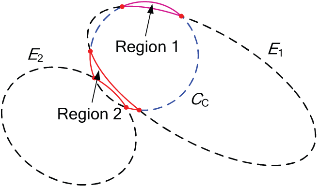
Cross section with more than one connected region.
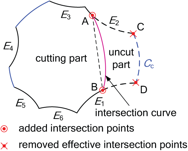
The algorithm introduced above can be applied directly in the third feeding stage. Alternatively, the result with this method is the same as that shown in the right part of Figure 13. In this figure, an assistant point is added on one circular arc to convert the self-intersecting polygon into a non-intersecting one, which is more understandable.
Decomposition of cross section in the third feeding stage.
As shown in Figure 9, the area of the cross section in the first feeding stage can also be calculated with the similar method as that in the second feeding stage. The only difference is that the area surrounded by line
Feedrate scheduling based on the MRR
The MRR is the stock material removed by one cutter tooth per minute. The maximum MRR in the feeding phase is adopted as the reference to schedule the feedrate since cutting parameters in multi-axis plunge milling are usually determined conservatively by this maximum cutting load. Then the scheduled feedrate fz,sch on each feeding depth is calculated using equation (13). Here, fz,con is the unscheduled constant feedrate, while max(SCS) is the maximum area of the cross section in the feeding phase

Experimental verification
Multi-axis plunge milling experiments
To verify the proposed feedrate scheduling method, multi-axis plunge milling experiments are performed in LEADWELL V-40 four-axis machining center, as shown in Figure 14. The workpiece in the experiments is a blank of open blisk forged with titanium alloy (Ti-6Al-4V). The cutters in the experiments are four flutes flat-end mills made with cemented carbide K40. The diameter and helix angle of the cutter are 10 mm and 40°, respectively. The rake, primary relief, and secondary relief angles of the bottom cutting edge are 4°, 8°, and 18°, respectively. Those of the side cutting edge are 5°, 10°, and 25°, respectively.
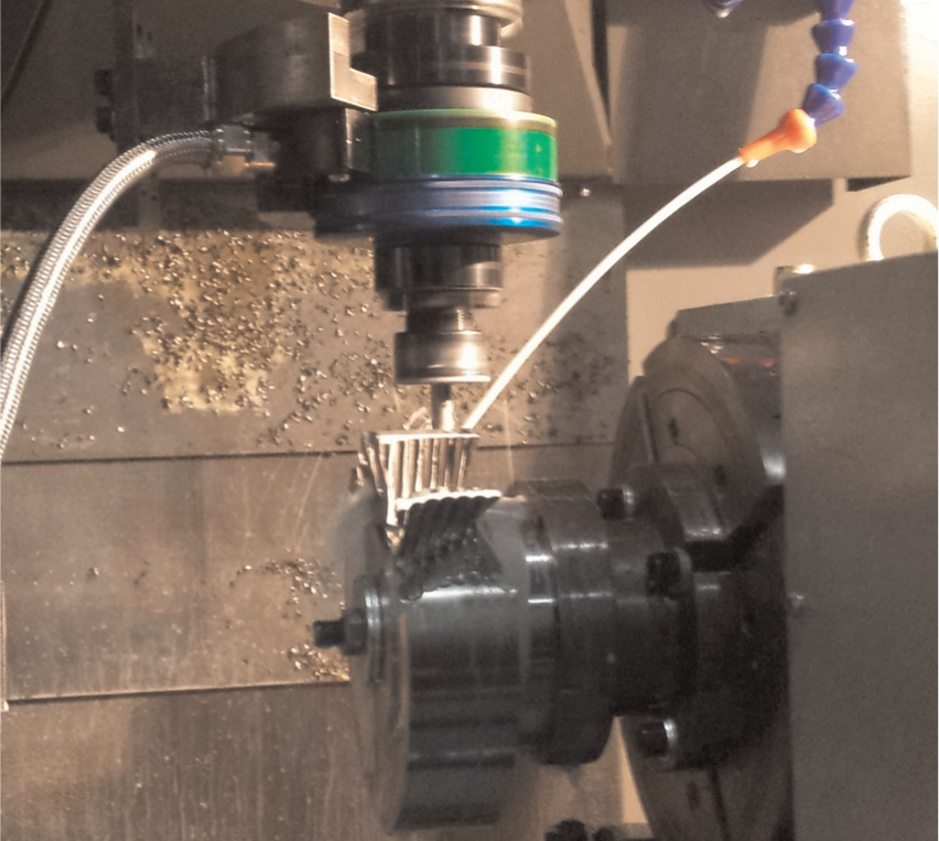
Plunge milling experiments.
Due to the restrictions of the experimental equipment, three groups of plunger paths are designed to simulate four-axis plunge milling. Before measuring the cutting forces and torque, two groups of plunger paths are conducted with a new cutter to remove a part of the stock material and form the desired blank shape for the third group. Then another group of new cutters cut the material with the constant and scheduled feedrate in the third group. In this group, the cutting forces and torque are measured with a Kistler rotating dynamometer (Model 9123C). The stock material removed in this group is shown in Figure 15.
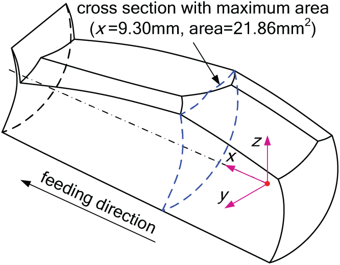
Removed material in the experiments.
Three feeding stages in the experiments are first calculated using equations (3) and (4) as
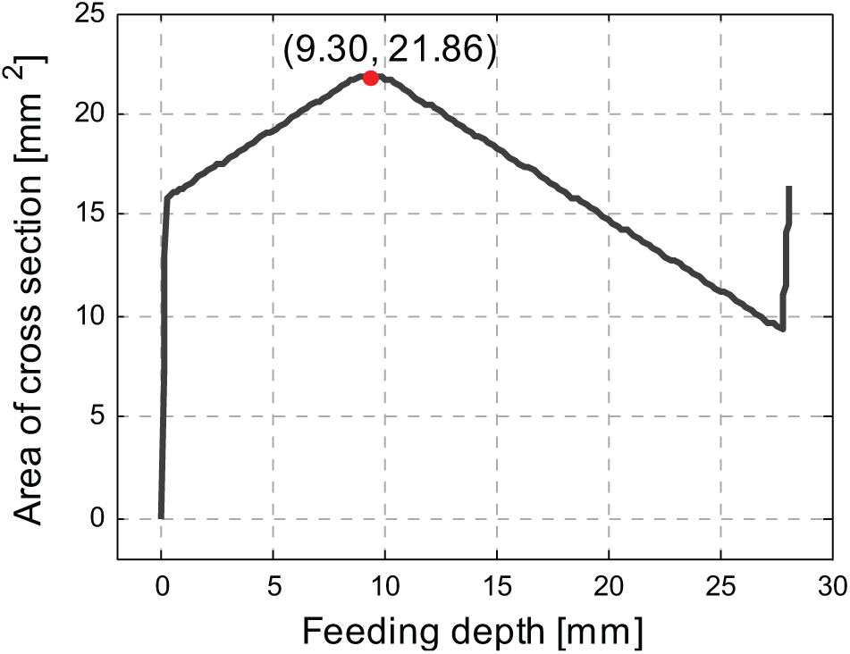
Calculated area of cross section in the feeding phase.
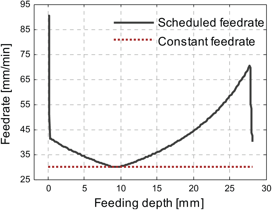
Constant and scheduled feedrate.
Results and discussion
In the experiments, cutting time, resultant lateral cutting force Fxy, axial cutting force Fz, and torque T are used to evaluate the proposed feedrate scheduling method. The lateral and axial cutting forces reflect the force loads along and perpendicular to the tool axis direction, respectively, while the torque reflects the torque load applied on the machine tool spindle. The results of the unscheduled constant feedrate and the MRR-based scheduled feedrate are shown in Figures 18 and 19, respectively.
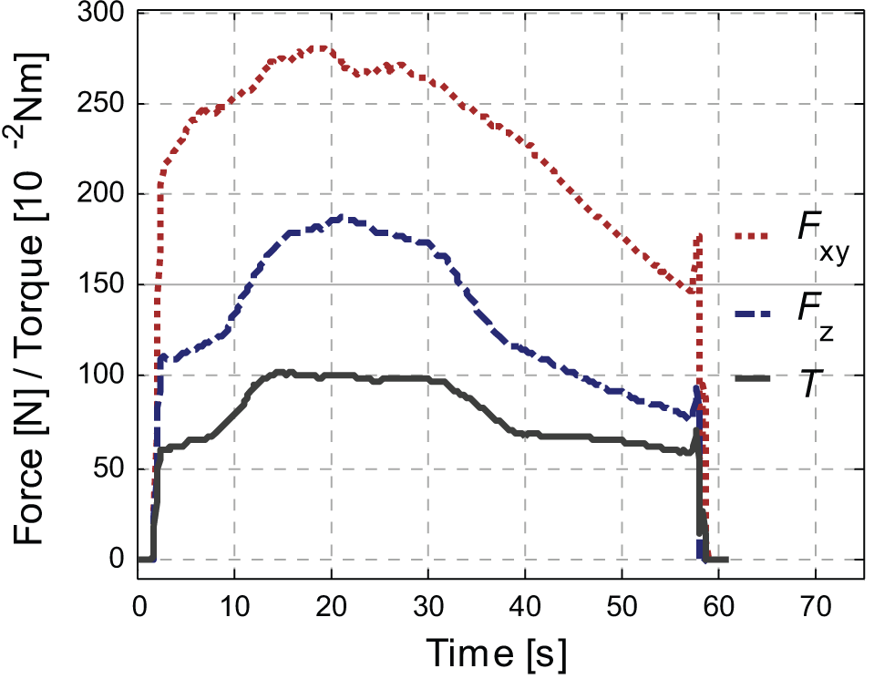
Results of the constant feedrate.
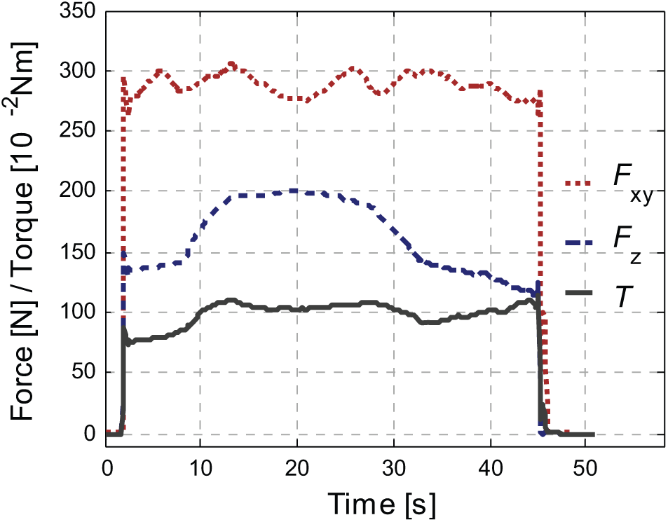
Results of the scheduled feedrate.
The total cutting time with the constant feedrate is 56.27 s, while it is 43.13 s after the feedrate scheduling. The proposed scheduling method reduces the cutting time by 23.35% in this case. The reduction of the cutting time would be more significant in five-axis plunge milling since the cross section in five-axis plunge milling usually changes more sharply and obviously than that as shown in Figure 15.
The maximum variances of the lateral cutting force Fxy, axial cutting force Fz, and torque T have significant reductions among the entire feeding phase. They are reduced from 275.29 N, 184.60 N, and 1.01 N m with the constant feedrate to 42.89 N, 86.67 N, and 0.41 N m with the scheduled feedrate, respectively. The main reductions of the maximum variances are owing to the first feeding stage, in which the cross-sectional area increases sharply from 0 to 16.32 mm2, as shown in Figure 16. Correspondingly, Fxy, Fz, and T increase from the theoretic 0 to 215.61 N, 111.49 N, and 0.60 N m, respectively, as shown in Figure 18. However, this feeding stage is very short (about 3.36% in length) in the entire feeding phase. The reduction of the cutting time in this feeding stage is only 5.18% of the total reduction. Although the maximum variances of cutting forces and torque are regulated remarkably, the improvement of the cutting efficiency caused by this feeding stage is not obvious in the entire feeding phase.
After the sharp increase of the cross-sectional area in the first feeding stage, the cutting process turns into a normal condition in the second and the third feeding stages. In these two feeding stages, the maximum variances of the lateral cutting force Fxy, axial cutting force Fz, and torque T decrease from 133.47 N, 128.83 N, and 0.72 N m to 41.02 N, 86.67 N, and 0.37 N m, respectively. They are reduced by 69.27%, 32.73%, and 48.61% with the proposed method, respectively. The proposed feedrate scheduling method can well regulate and smooth the force and torque loads, especially the lateral cutting force. This is very beneficial to improving the cutting conditions of multi-axis plunge milling since the cutter has the lowest rigidity in the lateral direction.
Conclusion and outlook
This article presents an original MRR-based feedrate scheduling method for multi-axis plunge milling of open blisks, which is a new perspective to improve cutting efficiency of plunge milling. The MRR in three feeding stages is calculated based on the identification and area calculation of the cross section. Then the feedrate is scheduled to keep a constant MRR in the entire feeding phase. The experiments indicate that the proposed method can effectively improve the cutting efficiency by reducing about 23% of the cutting time in the experimental case. The variances of the force and torque loads are all well smoothed in the entire feeding phase. This feedrate scheduling approach can be applied in multi-axis plunge milling of other complex parts in industry, such as closed blisks and impellers. A mechanistic-based feedrate scheduling strategy of multi-axis plunge milling will be introduced in another work, which is more flexible and accurate. However, this MRR-based method still has its particular advantages for the simple manipulation and rapid realization.
Footnotes
Appendix 1
Declaration of conflicting interests
The authors declare that there is no conflict of interest.
Funding
This work was supported by the National Science and Technology Major Project on CNC Machine Tool, China (grant number 2013ZX04001081).