
Abstract
In the process of plunge milling, the main cutting force is along the axial direction, and usually, the machining system has good axial rigidity, so it can withstand large cutting loads. This characteristic makes plunge milling particularly suitable for high-efficiency rough machining and semi-finishing of difficult-to-cut materials. The cutting force in the plunge milling process is usually large, and when the process parameters are not selected properly, the plunge milling is prone to the back-off phenomenon. In view of the characteristics of large cutting force and high cutting temperature in Inconel 718 plunge milling process, considering the small displacement of the actual tool tip caused by cutting force and cutting vibration, this article establishes a plunge milling force model based on the combination of analytical method and three-dimensional finite element method. The micro-displacement caused by vibration is obtained through dynamic modeling and modal test methods. Combined with the macro-displacement of cuter back-off under the action of the cutting force during the single-tooth run-in and run-out process, the modified cutting layer parameters are obtained, and optimized cutting force of plunge milling is obtained.
Introduction
Plunge milling, also known as Z-axis milling, is typically characterized by a feed motion along the Z-axis. With the large axial cutting force and the small radial and tangential cutting force, plunge milling is suitable for efficient rough machining and semi-finishing of difficult-to-cut materials such as high-temperature alloys, titanium alloys and high-strength steels.
A lot of works, especially the process optimization, the mechanism of chip formation, cutting force and tool wear, and so on, have been done on plunge milling process. Wakaoka et al. 1 studied the geometrical angle of the plunge cutting tool and the influence of the plunge cutting process on the perpendicularity of the high-precision vertical plane. Chen and Abdelkhalek 2 established a new approach to generate the shortest paths for pocket plunge milling. Witty et al. 3 investigated the performance and stability of plunge milling; the meshing state of the tool analyzed according to micro-geometry of the tool and the milling process parameters. Liang et al. 4 proposed an approach to adjust the cutting forces and torque by scheduling the federate during multi-axis plunge milling.
Some scholars have also studied the cutting force of plunge milling and its influence on the plunge milling process. Zhuang et al. 5 provided an empirical formula and developed a new cutting force model during plunge milling. The cutting force can be predicted accurately by adopting the new model. Ventura et al. 6 developed a cutting force model based on the kinematics of the process and the tool’s special features to predict the mean forces generated during the plunge operation. Low sensitivity of the static force components of tool flank wear and minor influence of the system on the dynamic behavior of the process are observed. Altintas and Ko7,8 presented the mathematical model of plunge milling process and predicted the cutting forces in axial and lateral directions and torque by considering the tool geometry, spindle speed and so on. The study showed the large torsional stiffness can reduce the chatter vibrations. Damir et al. 9 proposed time domain simulation model to predict the cutting forces and used a horizontal approach to calculate the chip area based on the contribution of the side and main edge, and the model can predict accurately cutting forces and system vibration. Al-Ahmad et al. 10 presented a cutting model considering chip and tool geometry, cutting forces and paths of cutting edge. Zhuang et al. 11 proposed an analytical and systematic cutting force prediction model, according to the cutter run-out phenomenon in plunge milling. The developed model was verified to be quite consistent with the measured cutting forces and can be used in various conditions of plunge milling process. Danis et al. 12 presented an analytical model, which can only use three instrumented tests to predict the cutting forces by considering edge radius and cutting parameters. Liang et al. 13 proposed an original approach to schedule the feed rate in multi-axis plunge milling of open blisks based on material removal rate. The cross-section in each feeding stage is then identified with a mathematic and geometric method. Its area is then calculated by its constituting elements, such as a polygon, circular arches and elliptical arches. Ko 14 provided a time domain model of plunge milling stability by considering dynamic motion of cutter center and cutting edge radius. This article estimated the machining stability and vibration by using an identified transfer function, and cutting forces were predicted by the time domain. Rafanelli et al. 15 presented a new approach to measure and calculate the cutting coefficients according to the traditional average force way in plunge milling. The influence of the radial engagement on the cutting coefficients can be evaluated by using this model, which provided a new method to adjust these values with different cutting parameters.
Cutting force modeling prediction has been receiving much attention, and many scholars have used a variety of methods to study the cutting force prediction. Pan et al. 16 developed an improved cutting force model based on the experimental investigation of end milling titanium alloy (Ti6Al4V) with polycrystalline diamond tools. The relationships between machining parameters and cutting force are established based on the introduction of the new cutting coefficients. Song et al. 17 presented a solid-analytical-based method to precisely and efficiently identify the cutter–workpiece engagements between the generalized milling cutter and workpiece being machined. And the undeformed chip thickness is calculated with respect to pre-defined tool coordinate system, which is regarded as the transformation form of feed cross-feed normal system by lead and tilt angles. Chen et al. 18 presented a model assuming a semi-stationary process for the serrated chip formation. To extend the predictive model to milling, the end mill is discretized into several axial slices, and an equivalent cutting edge is used to include the end cutting edge effect caused by the first axial slice. Pantale et al. 19 performed a two-dimensional and three-dimensional (3D) simplified modeling of the milling force of the alloy steel milling process and attempted to model and analyze the spiral milling cutter and obtained a near-realistic chipping chip. The shear effect and the plowing effect were expressed by the concentrated cutting force coefficient.20,21
Artificial neural networks and genetic algorithms are also used to predict cutting forces. Zuperl et al.22,23 established a neural network prediction model for ball-end milling forces, mainly considering the influence of cutting conditions such as tool diameter, spindle speed, axial depth, radial depth of cut and cooling conditions. Ratchev et al. 24 used the neural network prediction model based on genetic algorithm to predict the cutting force of complex thin-walled parts and studied the deformation control of thin-walled parts. Omar et al. 25 introduced a generic model to predict the cutting forces. Their model presented an improved method to compute the instantaneous chip thickness, considering the effect of tool deflection, tool run-out, system dynamics and so on.
From the literature review, the previous cutting force models for plunge milling were usually based on experimental data or analytical model, in which large test must be done or deviation due to the inaccuracy of some model parameters often occurred. In this article, a combination of analytical modeling and finite element (FE) simulation modeling was used to predict the cutting force of plunge milling based on the mechanism of high-temperature alloy Inconel 718 plunge milling process. The FE prediction method of cutting force is reflected in the research work of many scholars,26–29 especially the 3D cutting force FE simulation has higher accuracy. However, the use of 3D FE modeling and simulation for plunge milling will make the prediction efficiency very low. In this article, considering the variation characteristics of undeformed cutting layer parameters caused by vibration and plunge milling force during the plunge milling process, the combination of mathematical modeling and FE analysis is used to predict the cutting force of the plunge milling cutter of the large rounded insert, which can be more accurate and efficient.
Plunge cutting force modeling
The actual cutting layer will be changed due to the vibration as large depth of cut is often used in plunge milling to obtain high material removal. The difference between plunge milling and side milling is that the radial depth of cut of plunge milling varies during the single cutting process of each tooth (the radial depth of cut of plunge milling is usually smaller than the tool radius), which results in a great change in the macro-displacement of the tool tip when the back-off phenomenon occurs. This increases the difficulty of implementing the plunge milling process. Figure 1 depicts the phenomenon that the actual motion trajectory does not coincide with the ideal motion trajectory due to the tool “back-off.”
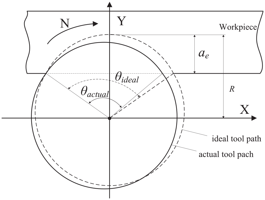
Schematic of difference between actual and ideal tool path by plunge bar deformation.
In this article, the influence of the tool deflection and the micro-displacement caused by the vibration on the cutting force are analyzed, and then the plunge milling force is predicted and applied to the optimization of plunge milling parameters. Figure 2 shows the roadmap for plunge milling force modeling. The microscopic displacement caused by the vibration, which lead to the change of undeformed chip thickness, is obtained by the plunge milling dynamics and the modal test. The macroscopic “back-off displacement” caused by the cutting force, resulting in the change of radial depth of cut, is then predicted. Therefore, the optimized plunge forces could be obtained by taking into account the effect of micro-displacement and macro-displacement.
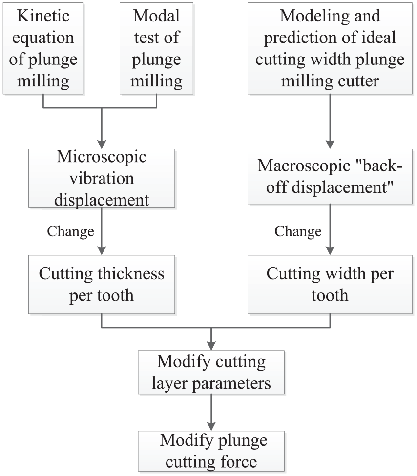
Schematic of parameter optimization of plunge milling.
Plunge milling dynamic equation
It is assumed that the structure experiences two lateral (x, y), axial (z) and torsional (θ) vibrations. At the same time, the transfer function of cutting force in all directions is set as Φαβ (α or β is x, y, z or θ), then the vibration displacement of tool under the action of cutting force in all directions can be expressed by equation (1)
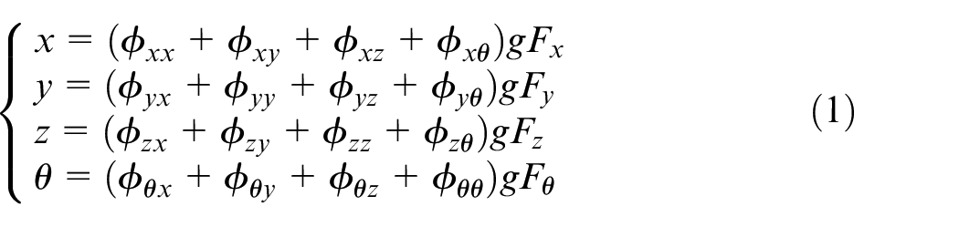
Also, the coupling between the torsional and axial displacements is considered. The frequency response function of each degree of freedom is measured independently through impact modal tests, and cross-coupling in lateral directions is omitted since they are negligible. Then equation (1) can be further expressed in matrix form as
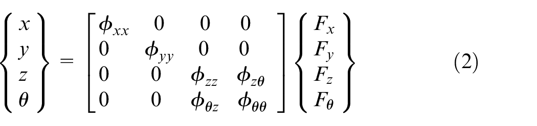
The first matrix on the right side of equation (2) shows the plunge milling modal parameter matrix, which is obtained by modal test. The second matrix is the cutting force of the plunge milling process, and then the modeling prediction is performed.
The direct transfer function of the tool tip point
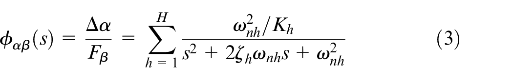
In equation (3),
Plunge milling force modeling
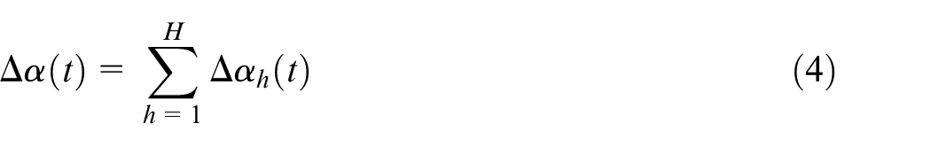
The cutting tool selected in the research work is integral interchangeable plunge milling cutter, and the tool information is shown in Table 1. The tool tip is designed into large rounded corners, and the rounded corner of the tool tip is 1 mm, which can effectively improve the strength of the tool tip and prolong the life of the cutter.
Information of plunge tool.
Since plunge milling is usually used for rough machining, the design of the cutting tool is mainly to ensure sufficient strength, so the tool structure is relatively simple, usually consider the following tool angles: Normal rake angle
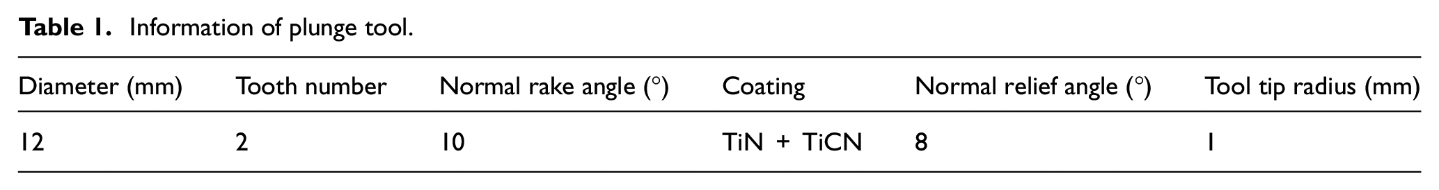
Figure 3 shows a schematic diagram of the plunge milling process. The biggest difference from the end mill is that the tool tip radius of the plunge milling cutter has a much greater impact on the cutting process than the end mill. This is because the bottom edge of the plunge milling cutter is the main cutting edge, and the side edge of the end mill is the main cutting edge, and the bottom edge is only the secondary edge of the end mill, which serves to protect the tool and naturally form the bottom surface.
Schematic of plunge milling.
During the plunge milling process, the rounded corners of the tool tip are most prone to excessive wear, resulting in tool failure; main forms of wear morphology are crater wear, flank wear and notch wear, as shown in Figure 4. This is because the cutting force and the direction of the cutting force are changed at each cutting portion of the circular arc cutting edge, and the cutting environment is relatively closed. From the wear part of the cutter, the circular arc edge must be taken into account in the cutting force modeling of the plunge milling cutter.
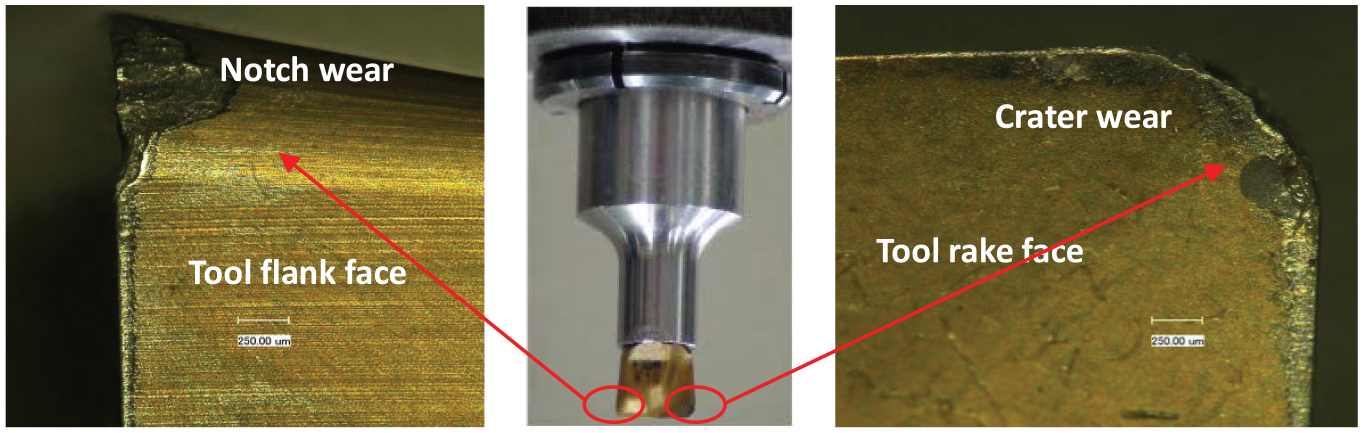
Plunge tool wear morphology.
Figure 5 shows a schematic diagram of the cutting force modeling of the large rounded plunge milling cutter, dividing the entire cutting edge into a straight portion AB and a circular arc portion BC. The cutting edge of AB straight section is in the radial direction, and thus the radial cutting component force dFr= 0. The cutting edge of BC circular arc section distributes the radial cutting force Fr, the tangential cutting force Ft and the axial cutting force Fa. The cutting edge of AB straight section can establish a two-dimensional right-angle cutting FE model. The cutting edge of BC straight section can be regarded as a series of micro-element for the variable thickness cutting process, and the plunge milling resultant force is Fsum=FAB+FBC.
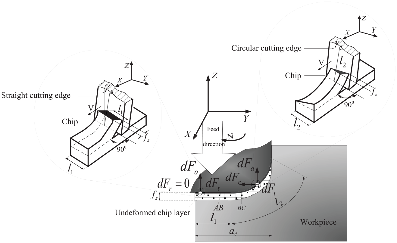
Schematic of cutting force modeling for plunge milling.
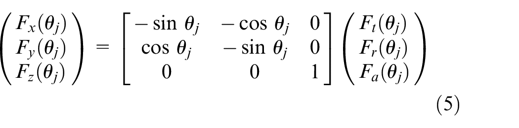
In order to establish the relationship between the FE predicted cutting force and the experimental measured cutting force, it is assumed that the angles between the tool edge and the positive X-axis are the run-in angle (θmin) and the run-out angle (θmax), and the position angle (the position angle is the angle between the line connecting the tooth reference point and the tool center and the Y-axis) at any time during the cutting process is θj, as shown in Figure 5. Based on the geometric relationship, the three-direction force on the cutting edge is converted into the cutting force measured by the dynamometer in the machine coordinate system
Substituting the cutting force in equation (5) into equation (1) and combining the modal test, the dynamic characteristics of the plunge milling can be obtained, and the micro-displacement caused by vibration in all directions can be obtained.
It should be noted that during the side milling process, the instantaneous cutting thickness is a function of the position angle with the run-in and run-out process of the teeth, while the instantaneous cutting width during plunge milling is a function of the position angle. Therefore, the cutting force at any position angle during the plunge milling process is the cutting force at the current moment, which does not need to be integrated and summed along the cutting edge. At the same time, it is noted that the change of the cutting force during the plunge milling process is caused by the change of the radial depth of cut (cutting width) during the run-in and run-out process.
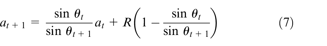
Figure 6 presents the change in the instantaneous cutting width of a single cutting edge during a complete run-in and run-out process. In the run-in and run-out process of the plunge milling cutter, the position angle
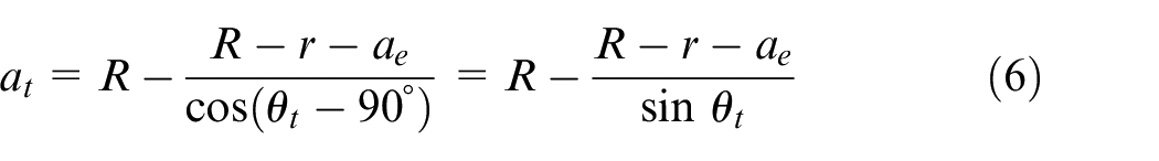
where R is the tool radius,
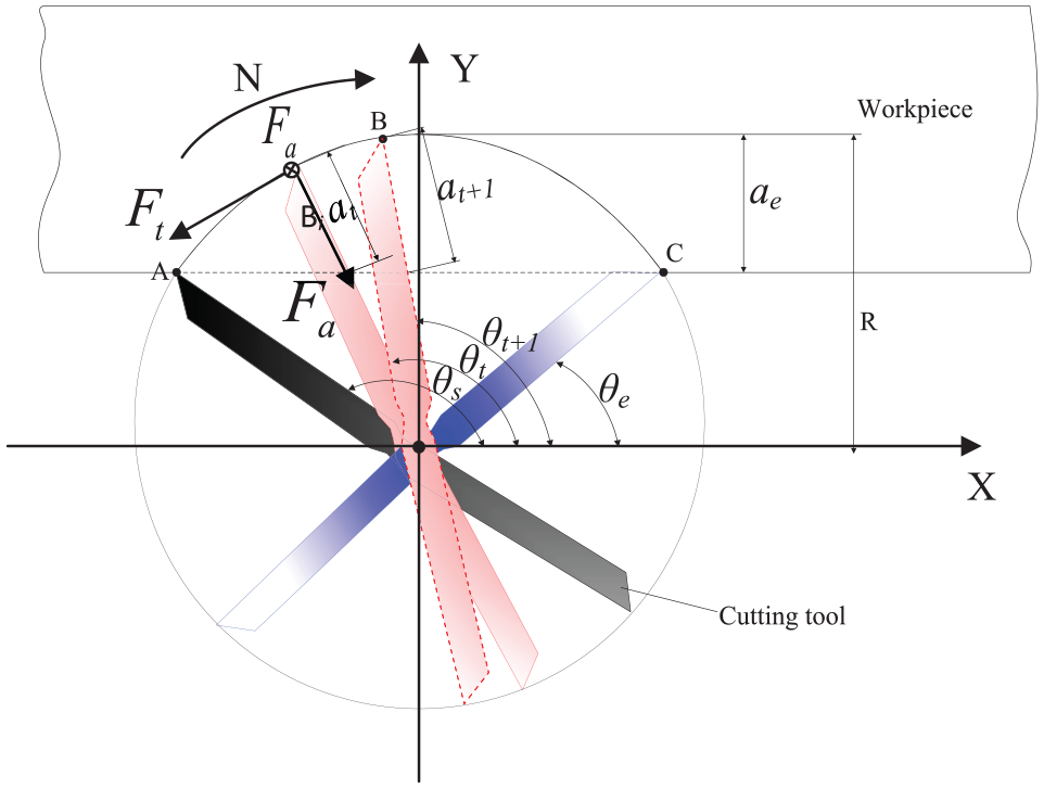
Schematic of transient variable width of cut in plunge milling.
The cutting force can be considered as the product of the cutting force coefficient (the cutting force per unit area) and the cutting area. Therefore, for plunge milling with only instantaneous width, that is, radial cutting depth varies with run-in and run-out of the cutting edge. The cutting force at the moment can be obtained by knowing the cutting force at time t+ 1. As shown in Figure 6, it can be found that the cutting force of the plunge cutting edge from point A to point B and then from point B to point C is constant during the run-in and run-out process. Therefore, different cutting widths corresponding to different position angles in the cutting process of AB and BC segments can be simulated separately, and then the cutting force of a cutting cycle can be fitted
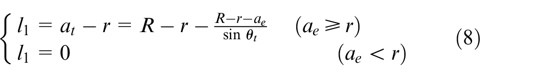
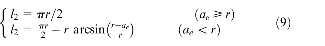
As shown in Figures 5 and 6, the instantaneous cutting width is the sum of the straight line segment and the fillet radius. According to the structural characteristics of the plunge cutting cutter and considering that the actual cutting edge length of the corner part changes little during the single-tooth run-in and run-out process, the cutting width of the circular arc edge is set as a constant value, and the cutting width
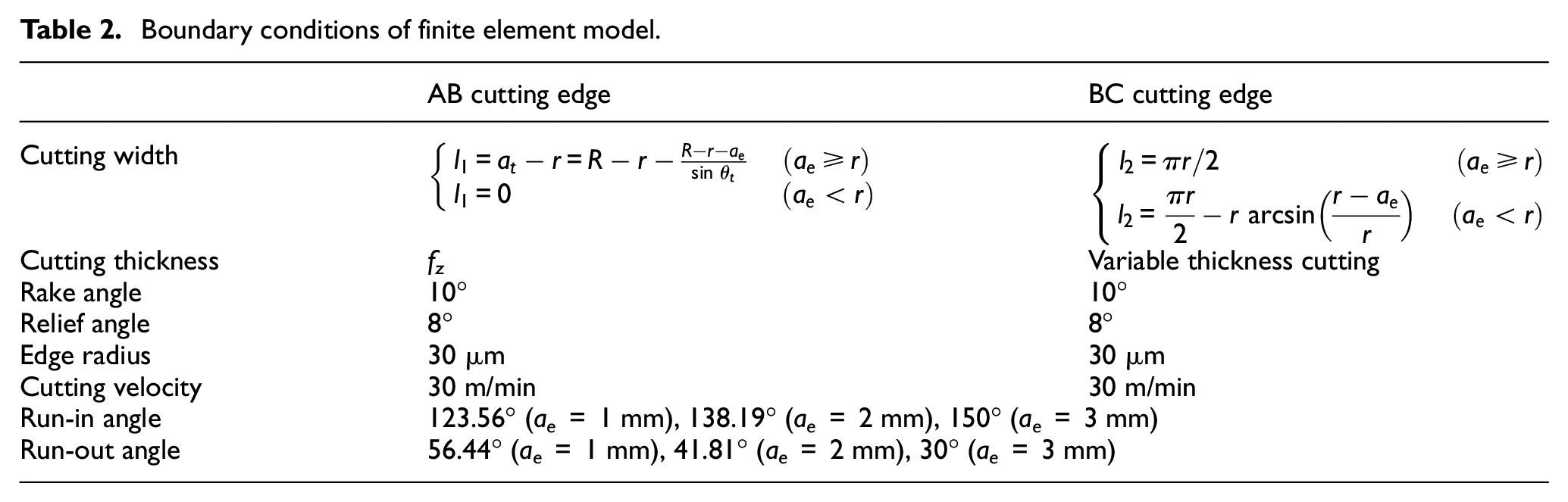
When the cutting width of the plunge milling is different, the run-in angle and the run-out angle under different cutting widths can be obtained according to the geometric relationship. Table 2 gives the boundary conditions that need to be determined in the FE model. It can be seen that all of the input parameters are constant except for the cutting width.
Boundary conditions of finite element model.
FE software Third Wave AdvantEdge™ is used for cutting force modeling. Figure 7 shows the stress distribution of the straight edge AB and the fillet portion of the cutter BC. It is noticed that the triangular undeformed chip layer was employed in the FE model of fillet portion BC. The extreme value of Mises stress during the cutting process of the fillet portion is 509 MPa; in contrast, the extreme value of Mises stress generated by the cutting edge of the straight line segment is about 760 MPa.
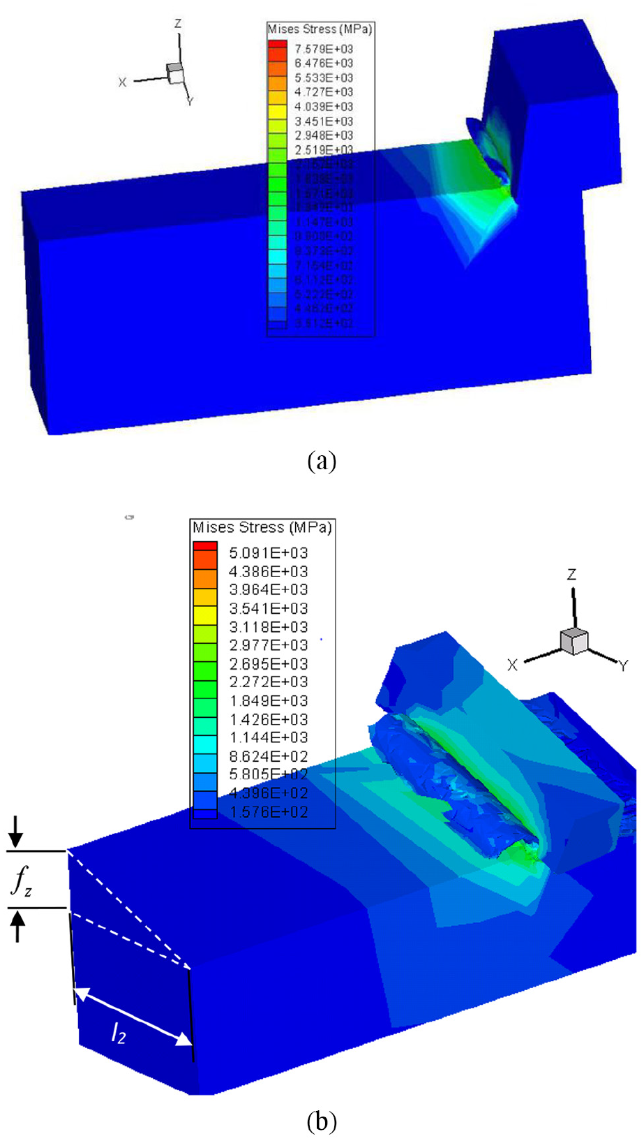
Simulated stress contour of plunge milling: (a) straight cutting edge AB and (b) circular arc cutting edge BC.
Verification of plunge milling force model
Plunge milling modal test
In order to verify the reliability of the cutting force model and obtain the modal parameters required for the dynamic equation of plunge milling, the corresponding milling experiments were carried out.
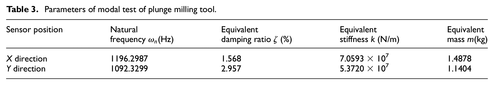
The test machine tool is DMU70V NC milling center, and 14% emulsified cutting liquid is used. KISTLER 9272 piezoelectric dynamometer, KISTLER 5017B charge amplifier and corresponding data acquisition and processing system were used to measure the cutting force. The hammer KISTLER 9724A2000, the acceleration sensor KISTLER 8452A and the data acquisition card NI-USB9233 were used to measure the modality. The workpiece material was Inconel 718. During the test, the workpiece was pressed with a pressure plate and bolted on the table, as shown in Figure 8. The experimental parameters are cutting speed of 30 m/min, feed per tooth of 0.05 mm, cutting width of 1, 2 and 3 mm, respectively. The modes of the cutter along X and Y directions are shown in Figure 9 and Table 3.
Parameters of modal test of plunge milling tool.
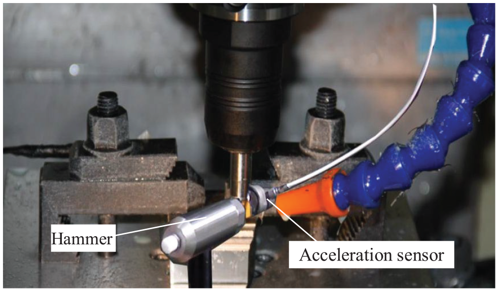
Modal test of plunge milling.
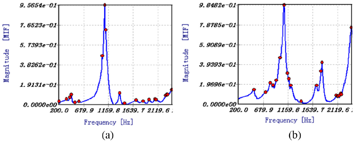
Results of modal test of plunge milling tool: (a) the mode of the cutter along X direction and (b) the mode of the cutter along Y direction.
Substituting the tool modal parameters in Table 3 into equation (2), and combining the cutting force into equation (1), the linear vibration displacement components generated by the cutting forces (Fx, Fy, F, Fz) can be obtained. By using the predicted cutting force as the input load on the plunge milling cutter, the macroscopic “back-off” displacement caused by the cutting force can be obtained, and the more realistic undeformed chip thickness as well as the corrected cutting force can be obtained.
Verification of plunge milling force model
Figure 10 shows the difference of the predicted cutting force whether to consider the vibration displacement and the “back-off” displacement of the plunge milling cutter. As can be seen from the figure, since the vibration and the “back-off” reduce the cutting thickness per tooth and the cutting width per tooth, the cutting force predicted by the modified model becomes small. It can also be found that when the cutting width is 3 mm, the thickness of the uncut layer caused by the vibration and the “back-off” also increases due to the increase of the cutting force. The cutting force predicted by the revised model decreases more than that when the cutting width is 1 and 2 mm.
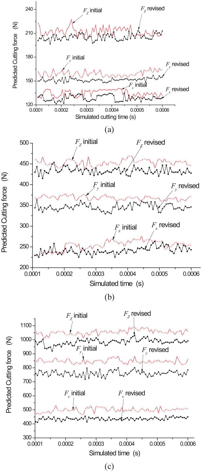
Predicted cutting force: (a) vc= 30 m/min, fz= 0.05 mm/z, ae= 1 mm, θt= 90°; (b) vc= 30 m/min, fz= 0.05 mm/z, ae= 2 mm, θt= 90°; (c) vc= 30 m/min, fz= 0.05 mm/z, ae= 3 mm, θt= 90°.
The fluctuations of predicted cutting forces mainly come from the FE method, which uses mesh as the basic element of numerical calculation, and its prediction value depends more on the mesh accuracy and the deformation degree. In order to improve the efficiency of 3D FE simulation calculation, local mesh refinement and self-adaptive technology are adopted. Both methods can make the remeshment continuously with the movement of the cutting tool in the cutting process, thus causing the fluctuation of cutting force to a certain extent.
Figure 11 shows the comparisons between the experimental and the simulated cutting force for a cycle with a cutting width of 1, 2 and 3 mm (cutting speed of 30 m/min, feed rate of 0.05 mm/tooth). In general, the simulation and experimental cutting forces are in good agreement. The experimental measurement value of Fy is quite different from the simulated prediction value, which is attributed to the larger variation of the radial cutting width of the cutter during the actual cutting process.
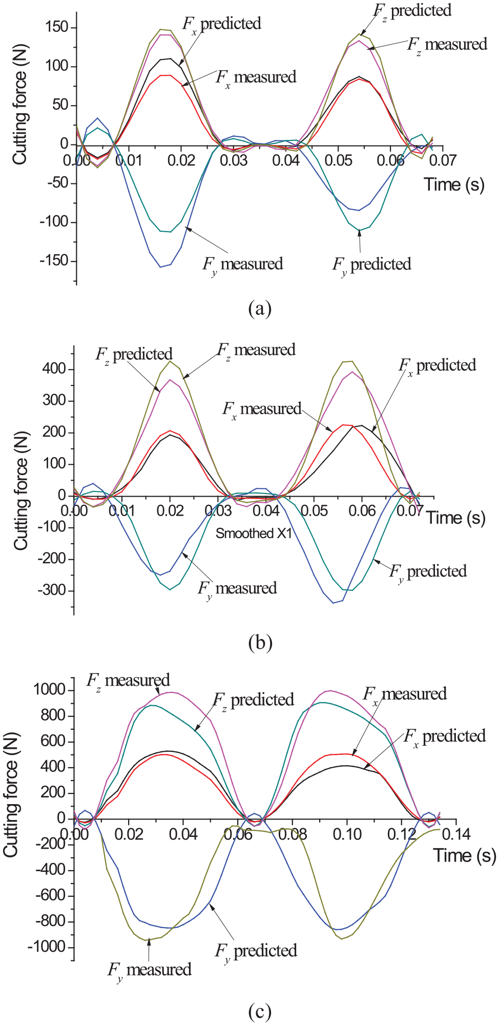
Comparison of predicted and measured force: (a) vc= 30 m/min, ae= 1 mm, fz= 0.05 mm/z; (b) vc= 30 m/min, ae= 2 mm, fz= 0.05 mm/z; (c) vc= 30 m/min, ae= 3 mm, fz= 0.05 mm/z.
It is noteworthy that when the cutting width is 1 mm, only the rounded corner of the tool tip is involved in cutting, and the cutting force changes with the feeding of each tooth. This is because the cutting force is distributed on the circular arc edge when the cutting edge is rounded. When the phenomenon of vibration and tool back-off appears, the change of undeformed chip layer is non-linear, resulting in the non-linear fluctuation of cutting force.
As shown in Figure 12, it can be found that the peak values of Fx, Fy and Fz are about 130, 210 and 200 N when the cutting width is 1 mm; the peak values of Fx, Fy and Fz are about 250, 350 and 430 N when the cutting width is 2 mm; the peak values of Fx, Fy and Fz are about 500, 810 and 930 N when the cutting width is further increased to 3 mm.
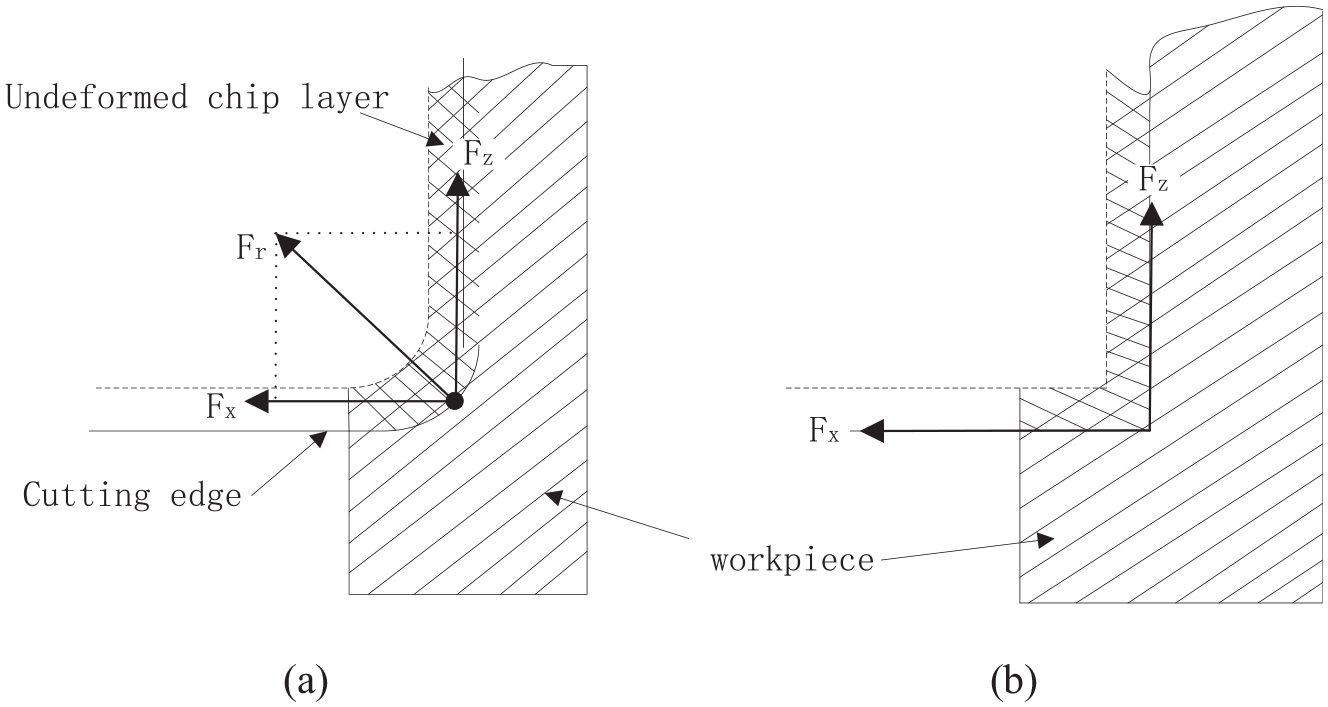
Schematic diagram of cutting force distribution: (a) cutting edge with fillet and (b) cutting edge without fillet.
From the comparison of cutting force values, it can be seen that when the cutting width increases from 1 to 3 mm, Fx equals to increase by three times, Fy almost increases by four times and Fz nearly increases by five times. The fillet edge participates in the removal of material as the radial depth of cut is 1 mm. Cutting force distribution in three directions would be affected because only the fillet edge participates in the removal of material when the radial depth of cut is 1 mm. In particular, Fz will be significantly reduced. More increase in Fz due to the decreased influence of fillet cutting edge when the radial depth of cut increases to 3 mm, which could be explained by Figure 12. From Figure 12(a), it is obvious that the cutting force of fillet cutting edge Fr has been dissipated into X direction, which may lead to a smaller Fz compared to that of sharp cutting tool. As the radial depth of cut increases, cutting force in Z direction will increase faster than the other two directions due to the decreased impact of fillet edge.
Relatively, the cutting force predicted by FE method is smaller with the increase of cutting width. With the increase of cutting width, tool vibration and wear increase, resulting in a faster increase in cutting force. Although the increase of cutting width is beneficial to improve material removal rate, excessive cutting force will make the tool bar prone to deformation and may cause vibration of the machining system.
Conclusion
In this article, a method of plunge milling force based on the combination of cutting force analytical model and 3D FE model is proposed for the plunge milling of superalloy Inconel 718. The accuracy of the model is verified by plunge milling experiments. The conclusion is given as follows:
According to the cutting characteristics of the circular cutting edge and the straight edge of the plunge milling cutter, the analytical model of the variable cutting thickness and the equal cutting thickness plunge milling force is established, and the 3D cutting force modeling of the discrete micro-element is used to reduce the workload of the FE calculation. It is able to quickly obtain accurate cutting forces, and the predicted cutting force is in good agreement with the experimentally measured cutting force.
The cutting force predicted by the nominal cutting layer parameters will be larger than the actual cutting force without considering the “back-off” displacement caused by the cutting force and the cutting thickness variation caused by the cutting vibration. This is because the “back-off” of the plunge milling cutter and the vibration causes the actual cutting layer to become smaller.
For plunge milling cutter with large fillet, Fz increases more significantly as the radial depth of cut increases. When the radial depth of cut is small, the fillet mainly participates in cutting, affecting the distribution of cutting force in three directions, especially reduces the Fz. As the radial depth of cut increases, cutting force in Z direction will increase faster than other two directions due to the decreased impact of fillet edge.
The cutting width has a great influence on the plunge milling process, and the increase in the cutting width causes the cutting force to increase rapidly. For large fillet plunger cutters, too small cutting width will result in large periodic fluctuations in the cutting force per tooth feed, which is detrimental to the cutting process.
Footnotes
Appendix 1
Declaration of conflicting interests
The author(s) declared no potential conflicts of interest with respect to the research, authorship, and/or publication of this article.
Funding
The author(s) received no financial support for the research, authorship, and/or publication of this article.