
Abstract
The reasonable selection of cutting parameters is of great significance to improve the productivity in high-speed machining process. In this article, a stability-based selection method of cutting parameters is proposed to increase material removal rate in high-speed machining process. First, the coupled dynamics of the high-speed spindle system and machining process is modeled. Then, the interaction mechanism between the spindle-tool system and the cutting process is investigated. Based on the process stability and surface quality of workpiece, a cutting parameter selection method is proposed from the perspective of machining stability. In order to select reasonable spindle speed and depth of cut, the lower bound of chatter stability lobe diagram and surface finish are taken as constraints, and the maximum material removal rate is set as the target. The proposed method is applied to the machining of the front face of a gearbox cover, which is made of Aluminum-7050. The axial depth of cut and spindle speed are chosen reasonably with the increase in machining efficiency by about 133%.
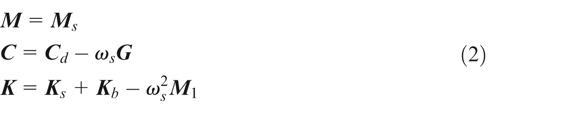
Keywords
Introduction
Due to the high material removal rates (MRR), high-speed machining technology has already been extensively used in the field of aerospace, die/mold and automobile. However, the reasonable selection of high-speed machining parameters is still an obstacle puzzling the industry. Inappropriate selection of cutting parameters may lead to chatter, which results in the damage of high value-added parts and cutter breakage/extra wear. In order to avoid chatter, many engineers select cutting parameters with traditional trial cut method. In most cases, conservative cutting parameters are chosen, which limit the performance of high-speed machine and productivity. Therefore, it is of great significance to study how to optimize the machining parameters with the view of improving machining efficiency, reducing damage cost of parts and so on.
The optimization of machining process has attracted wide attention, leading to extensive study from different perspectives such as tool tilting angle, tool path and cutting parameters. Among all these methods, the optimization of cutting parameters is highly popular due to its crucial effects on tool life, processing stability and workpiece quality. In the past, extensive research had been carried out in this area. Benardos and Vosniakos 1 presented a review of the different approaches based on machining theory, experimental investigation, design of experiments and artificial intelligence techniques in optimizing machining process parameters. Mukherjee and Ray 2 reviewed the optimization techniques in metal cutting processes, which were classified as conventional and non-conventional (evolutionary) optimization techniques. Conventional techniques were broadly classified into two categories, that is, experimental techniques and iterative mathematical search techniques. In the first category, experimental techniques include statistical design of experiment, such as Taguchi method, and response surface methodology (RSM). In the second category, iterative mathematical search techniques, such as linear programming, nonlinear programming and dynamic programming algorithms were included. Non-conventional optimization techniques were based on genetic algorithm (GA), tabu search (TS) and simulated annealing (SA). Yusup et al. 3 gave an overview and the comparison of the five-year researches from 2007 to 2011 that used evolutionary optimization techniques to optimize machining process parameters of both traditional and modern machining. Five techniques were considered, namely, GA, SA, particle swarm optimization (PSO), ant colony optimization (ACO) and artificial bee colony (ABC) algorithm.
Since milling is one of the most common cutting processes, the optimization of cutting parameters in milling process is developing very fast in recent years. The GA algorithm, which is based on the natural process of evolution to solve optimization and search problems, is widely applied in optimization of machining process parameters. Rai et al. 4 proposed a physical model named GA-MPO (genetic algorithm–based milling parameter optimization system) for the prediction of the optimal cutting parameters (namely, axial depth of cut, radial immersion, feed rate and spindle speed) in the multi-tool milling of prismatic parts. Aggarwal and Xirouchakis 5 developed a GA-based optimization system to automate the selection of the cutting conditions for the minimization of pocket milling time. Alrashdan et al. 6 used the GA to optimize a multi-objective cost function derived based on energy consumption and three machining parameters (feed, speed and depth of cut) needed to improve the surface finish in the end milling machining process of AISI D2 steel. Another very popular evolutionary algorithm is the PSO algorithm, which was introduced to solve continuous optimization problems. Raja and Baskar 7 carried out experiments to study the effect of machining parameters on surface roughness in face milling process and developed a mathematical model for surface roughness prediction using PSO on the basis of experimental results. Thepsonthi and Özel 8 optimized the axial depth of cut and feed rate using experimental, statistically based modeling and multi-objective PSO methods to minimize the surface roughness and burr formation in micro-end milling process.
The combination of evolutionary techniques in optimizing machining parameters is also a developing trend. Khan et al. 9 developed two hybrid neural network models, namely, genetic algorithm–based neural network (GA-NN) model and particle swarm optimization–based neural network (PSO-NN) model to find the optimal cutting conditions, and the objective considered was the minimization of unit production cost subjected to various machine constraints. Zuperl et al. 10 built an off-line optimization and feed-forward neural control scheme (UNKS) based on the hybrid process modeling to control the cutting force adaptively and maintain constant roughness of surface being milled. Aykut et al. 11 proposed a new multi-objective optimization approach to obtain robust optimum values for cutting conditions in the face milling of cobalt-based alloys. Minimizing cutting forces and maximizing the material removal were considered as objectives. Fu et al. 12 acquired optimal combination of cutting parameters by coupling gray relational analysis with principal component analysis to establish a correlation among spindle speed, feed per tooth and depth of cut to the three directions of cutting force in high-speed milling on NAK80 mold steel. In order to optimize surface roughness, MRR and cutting energy, Yan and Li 13 proposed a multi-objective optimization method based on weighted gray relational analysis and RSM to select optimal spindle speed, feed rate, depth of cut and width of cut in milling process. Sivasakthivel et al. 14 used the Taguchi method–based gray relational analysis to optimize the machining parameters in end milling operation. Erkan et al. 15 used the Taguchi method and genetically optimized neural network systems (GONNs) to select optimal cutting parameters and obtained minimum surface roughness in the milling of glass-fiber reinforced polymer composite (GFRP) materials.
Considering that conventional cutting parameters optimization methods are based on the assumption that the dynamics of the milling system is deterministic, Zhang et al. 16 developed a robust spindle speed optimization formulation where the upper bound of surface location error and lower bound of lobe diagram were adopted as the optimization object and the constraint condition, respectively. Zhang and Ding 17 also proposed a machining parameter optimization model based on the milling dynamics, in which the spindle speed was optimized to minimize tool vibration response and maximize material removal simultaneously with the constraint conditions of keeping the milling process chatter-free. Song et al. 18 optimized spindle speeds and depth of cut simultaneously based on the vibration frequency analysis during milling processes to obtain the most stable cutting process in relative stable region (or conditional stable region), achieving higher MRR and higher surface accuracy.
From the literature review of cutting parameters optimization in milling process, most research works are merely concentrated on the cutting process itself, and cutting parameters are optimized according to the influence of cutting parameters on surface roughness, machining/production costs, MRR, processing time, cutting forces, tool life and so on. Advanced optimization techniques are over emphasized, rather than the interaction mechanism between the machine tool and cutting process. In 2009, Brecher et al. 19 pointed out that it is not due to the incorrect planning of machines or processes, but rather due to the additional action arising from the interaction between machine tool and cutting process, which leads to problems such as poor surface quality, drastic reduction in tool life and service performance degradation of machine tool components in most cases.
As one of the core components in high-speed machine tool, the high-speed spindle affects the dynamic characteristics of machine tool structure directly. In high-speed machining condition, the coupling mechanism between cutting process and the high-speed spindle becomes more complicated. Extensive research has been carried out so far, and remarkable accomplishments are made in terms of the theoretical modeling of high-speed spindles. Lin et al. 20 presented an integrated model to study various thermo-mechanical-dynamic spindle behaviors at high speeds and relevant effects like the bearing preload effects, high-speed rotational effects (including centrifugal forces and gyroscopic moments) and the spindle dynamics. However, it is not until recent years that some research has combined dynamic/thermal spindle model with high-speed machining process together to analyze the machining performance of high-speed spindles. Cao and Altintas 21 developed a general method to model spindle assembly by modeling the spindle shaft and housing as Timoshenko’s beam considering the centrifugal force and gyroscopic effects and by modeling the bearing as a standard nonlinear finite element based on Jones’ bearing model considering the centrifugal force and gyroscopic effects. Li and Shin 22 proposed a comprehensive integrated thermo-dynamic model consists of fully coupled three sub-models (i.e. bearing, spindle dynamic and thermal models). The thermal model is generated using a finite element approach, and the spindle dynamic model is constructed using finite elements based on Timoshenko beam theory. Using the new thermo-dynamic model, more general and detailed bearing configurations can be modeled through a systematic coupling procedure. Considering the dynamic effects due to high rotational speed and elastic deformations, Gagnol et al. 23 predicted a new dynamic stability lobe diagram by integrating the modeled speed-dependent spindle transfer function in the chatter vibration stability approach of Altintas and Budak. Li and Shin 24 et al. integrated the high-speed spindle mechanical–thermal coupling model with cutting process model and preliminarily proposed the basic framework of digital machining system. Holkup et al. 25 presented a finite element method–based thermo-mechanical model of spindles with rolling bearings. The predicted bearing properties are used to estimate the changes in the dynamic behavior of spindles. Jiang and Zheng 26 established a double-rotor model of spindle-drawbar-bearing assembly by utilizing the whole transfer matrix method (WTMM) and a nonlinear rolling bearing dynamic model including the centrifugal force and gyroscopic effects. Cao et al. 27 studied the changes of dynamic properties of high-speed spindle with centrifugal force and gyroscopic moment and predicted the chatter stability region in high-speed milling with consideration of speed effects. Nevertheless, it is a difficult task to understand the interaction mechanism between the high-speed spindle-tool system and cutting process. The reasonable selection of cutting parameters in high-speed milling is still an unsolved problem.
In this article, a coupled dynamic model of the high-speed spindle-tool system and cutting process is proposed first. Then the interaction mechanism between the dynamic properties of the high-speed spindle-tool system and the machining process is investigated. Based on the process stability and surface quality of workpiece, a cutting parameter selection method is proposed and then applied to the high-speed milling of the front face of a gearbox cover as a case study.
Integration modeling of spindle–process interaction
High-speed spindle is a key part involved in cutting process. Modeling of cutting process and machine tool dynamics are not independent of each other, but are linked closely and promote mutually. We can utilize the dynamical model of machine tool structure for dynamic prediction of cutting process and then optimize the cutting process. Conversely, the dynamic characteristics of machine tool structure are also influenced by cutting process and have obvious nonlinear properties, which need to be modified by considering the effect of cutting process. Accurate prediction for the processing performances of machine tool and reasonable explanation of the complex physical phenomenon in cutting process are obtained only when integrating the machine tool structure model and processing model as a coupled dynamic system.
Dynamic modeling of the high-speed spindle-tool system
The high-speed spindle system contains many kinds of parts, which could be mainly divided into two subsystems, that is, spindle components subsystem and bearing subsystem. Being different from traditional spindle, the modeling of high-speed spindle must take the centrifugal force and gyroscopic effect into account. The spindle components subsystem is usually composed of parts with axial symmetric structures like rotor, motor, pulley, drawing bar, tool, sleeve and spindle housing. Finite element modeling is performed on beam-type structure such as rotor, drawing bar and spindle housing with Timoshenko beam element and on disc-type structure such as pulley, sleeve with disk element. As for the spindle bearing, considering the centrifugal force, gyroscopic moment and thermal deformation, we extend Jones bearing model and establish a nonlinear bearing model. Finally, by integrating the theoretical models of spindle and bearing components, the motion equation of the whole spindle system is obtained as shown in equation (1)

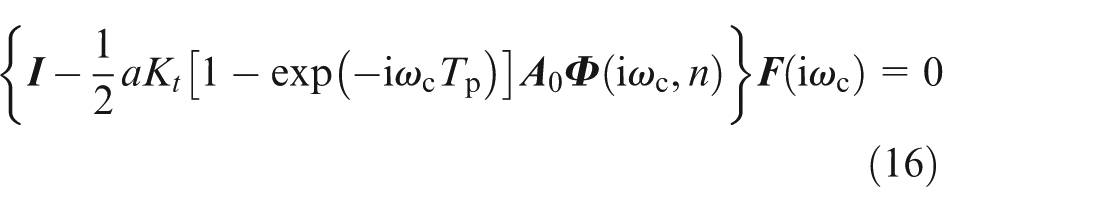
where
where
Modeling of the interaction process of high-speed spindle-tool system and milling process
The relative vibration between tool and machined surface will affect the surface finish, chip thickness, dynamic cutting force and so on. Cutting force could be predicted based on given tool geometrical parameters, workpiece material constants and cutting conditions. On this basis, the vibration of tool and workpiece and relative vibration between them could all be calculated. Then, we could simulate the surface finish of workpiece.
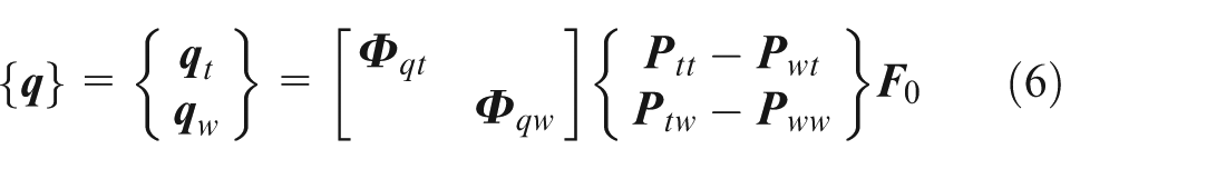
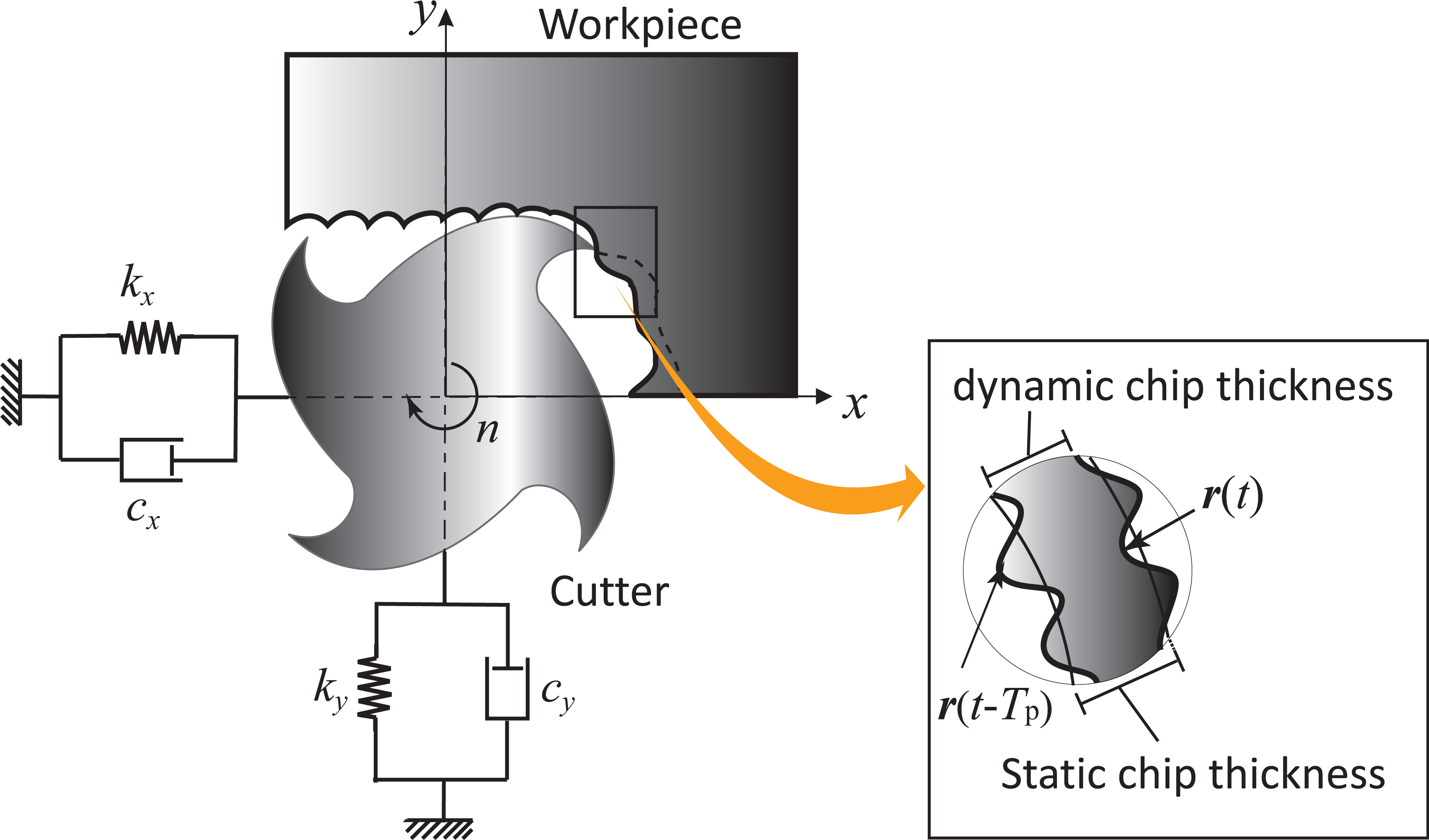
In cutting process, the tool and workpiece bear cutting force, which are equal but in opposite direction. If we describe the tool (subscript t) and workpiece (subscript w) structures with a 2-degree-of-freedom system, the displacement vector and the force vector can be represented as

The motion equation of the tool-workpiece system takes the form

Thus, we can derive the modal matrix
With the modal coordinate transformation equation

Modal displacement vector
Substituting above equation into equation (5), we obtain the vibration of the tool and the workpiece under cutting force excitation, respectively
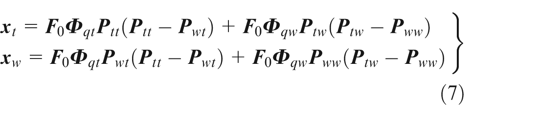
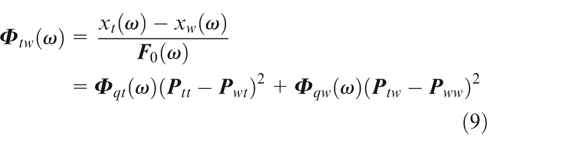
The relative vibration between the tool and the workpiece will be presented in following form

Then, we can simulate the final dimensional accuracy and surface finish with the relative displacement.
When machine tool structure is excited at the cutting point by harmonic forces, the relative transfer function between the tool and the workpiece can be written in the form
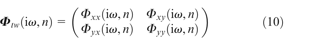
When spindle speed is n, the transfer function matrix of high-speed spindle-tool system in two orthogonal directions x and y can be written as
where
Considering the dynamic properties of the tool in two orthogonal directions, that is, feed direction x and normal direction y, the dynamic milling process is shown in Figure 1.
Dynamics of milling process.
Cutting forces generated in milling process excite the machining system in x and y directions, respectively. Assuming that vibration waviness or dynamic displacement
The corresponding change of dynamic chip thickness in two neighboring tooth passing period is

Dynamic cutting force 29 has the form
where
Let the frequency-domain expression of dynamic cutting force

The change of dynamic chip thickness

Transform equation (13) into frequency domain and substitute equation (15), it follows that
where

Combining the dynamic properties
The proposed method of cutting parameter selection
The flowchart of cutting parameters selection is shown in Figure 1, consisting of input layer, modeling layer, output layer and decision layer. We will give the explanation of content in each layer first and then introduce the corresponding workflow.
Input layer
It includes geometrical and physical parameters of the spindle-bearing system, preload state of bearing, initial given cutting parameters (spindle speed, depth of cut and feed rate) and so on. This section will provide data support for the modeling of machine tool spindle structure and machining process.
Modeling layer
It includes two parts, that is, the dynamic modeling of spindle-tool system and modeling of cutting process. The dynamic model of the spindle-tool system is a finite element model composed of tool, tool holder, rotor, bearing, spindle housing and other accessories. The bearing stiffness dynamically varies with the change of spindle speed and cutting condition. For given cutting parameters, the modeling of cutting process is, in fact, the prediction of dynamic cutting force. Taking dynamic cutting force as the input of dynamic model of the spindle-tool system to ensure the efficient integration of the spindle-tool model with cutting process, we will obtain the dynamic properties of spindle in high-speed machining condition. Under the excitation of cutting force, vibration responses of the spindle-tool system can be computed numerically.
Output layer
It is the output of the integrated model of dynamic properties of spindle-tool system with cutting process, which consists of two aspects, that is, chatter stability prediction and surface roughness prediction. The chatter stability prediction is based on the FRF at the cutting point, reflecting relative stiffness of the tool-workpiece system. We can utilize the FRF at tool tip to predict cutting stable region so as to avoid chatter. The latter mainly refers to the relative vibration response of the tool-workpiece system under the effect of dynamic cutting force. We can calculate the vibration response of displacement, velocity and acceleration, with the purpose of predicting surface quality such as waviness and surface roughness.
Decision layer
It takes advantage of the information in output layer, including cutting stability, surface finish to evaluate the machining performance of the present spindle-tool system. If the current machining performance is satisfactory, then continue to maintain; otherwise, the optimization of cutting parameters is carried out.
The machining process is a typical closed-loop system as shown in Figure 2. We can model the spindle-tool system and cutting process, respectively, and then integrate them based on the input of system (i.e. spindle-tool parameters and cutting parameters). Utilizing the integrated model of spindle–process interaction, we could predict the FRF at the tool tip, the relative vibration between the tool and the workpiece and so on. On the basis of this, the cutting stability and surface quality of the workpiece are predicted. Eventually, we could assess the machining performance of the spindle-tool system under current condition and determine whether optimization operation is necessary based on comprehensive consideration of the cutting stability and machining quality.
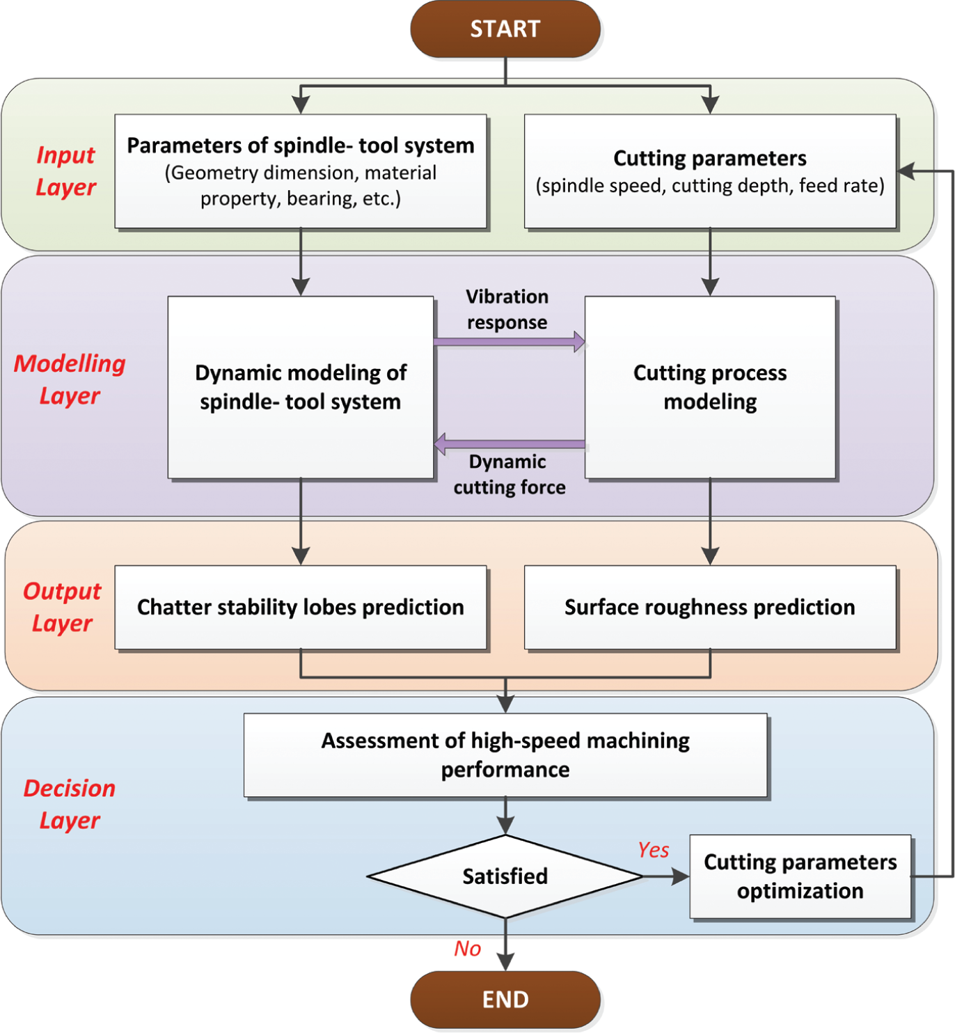
The flowchart of cutting parameter selection.
Case study
Based on the above analyses, in this section, we will use the proposed method to optimize cutting parameters for the sake of achieving greater machining efficiency by selecting reasonable depth of cut and spindle speed from the perspective of high-speed milling stability. The inside wall of the front-end surface of gearbox cover was machined with high-speed machine tool, and the material of workpiece is Aluminum-7050.
Input layer
The input includes geometrical and physical parameters of the spindle-bearing system, preload state of bearing, initial given cutting parameters (spindle speed, depth of cut and feed rate) and so on.
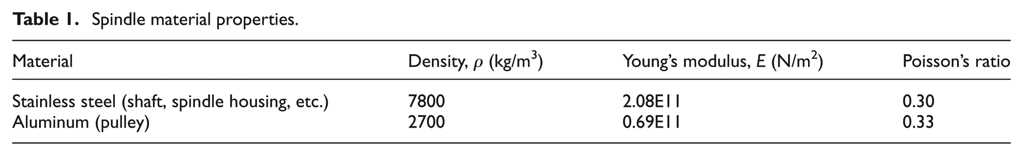
In this case study, the high-speed spindle of a vertical machining center is considered, as shown in Figure 3. The detailed geometry size of the spindle is open for us, and the material properties are shown in Table 1. All bearings in spindle are angular contact ball bearings and the maximum DmN value is about 1.3 million. The structural parameters and material properties of bearing are listed in Tables 2 and 3, respectively.
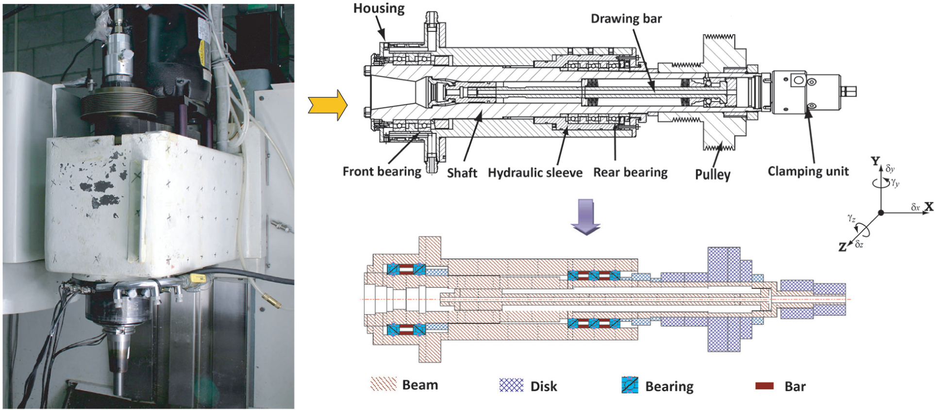
The high-speed spindle system (Courtesy of Manufacturing Automation Laboratory at The University of British Columbia).
Spindle material properties.
Bearing structural parameters.
Bearing material properties.
The depth of the inside wall of the front-end surface of gearbox cover is 15 mm, which belongs to typical pocket machining. Cutting parameters before optimization is shown in Table 4.
Cutting parameters before optimization.
Modeling layer
It consists of the dynamic modeling of spindle-tool system and modeling of cutting process. Based on the analysis of the spindle system, we establish a dynamic model of the spindle-tool system including components such as tool, tool holder, rotor, bearing, spindle housing and other accessories. With this dynamic model, we can calculate the natural frequency, dynamic response and FRF at any node of the spindle-tool system.
We simulate the FRF Hxx in X direction, the FRF Hyy in Y direction and the cross FRF Hxy between X and Y directions at the tool tip, respectively. The simulation results are displayed in Figure 4.
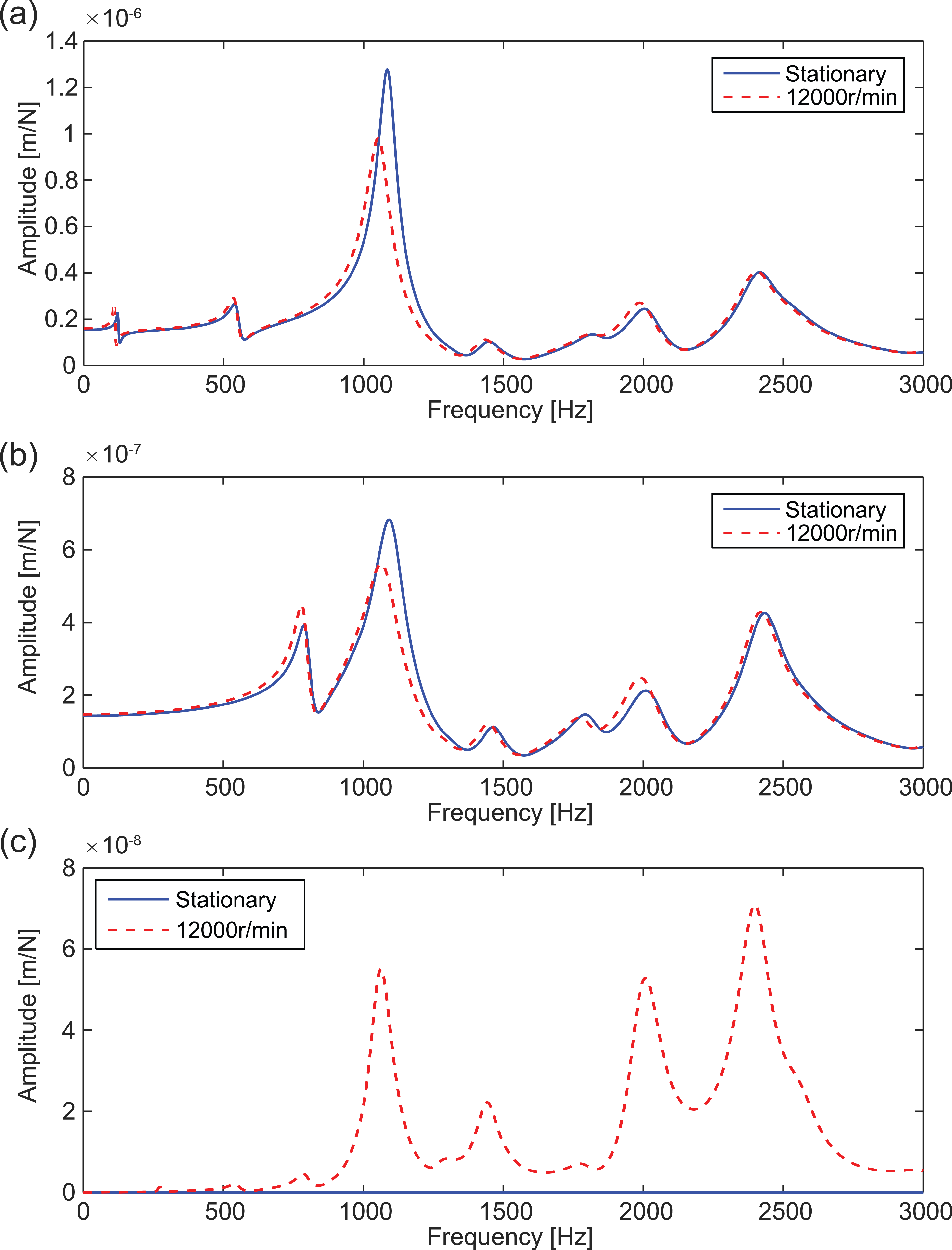
Simulated FRFs at the tool tip: (a) FRF in X direction: Hxx, (b) FRF in Y direction: Hyy and (c) cross FRF in X and Y directions: Hxy.
Comparing the FRFs at tool tip in two conditions (i.e. stationary state and spindle speed 12,000 r/min), it can be found that with the increase in spindle speed, stiffness of system has decreased, leading to the drop of natural frequency and shift of tool tip FRF toward low frequency range (Figure 4(a) and (b)). In addition, due to the effect of gyroscopic moment, the cross FRF Hxy in X and Y directions appears (Figure 4(c)).
In terms of cutting process modeling, we first determine the start
Cutting force coefficients of Aluminum-7050.
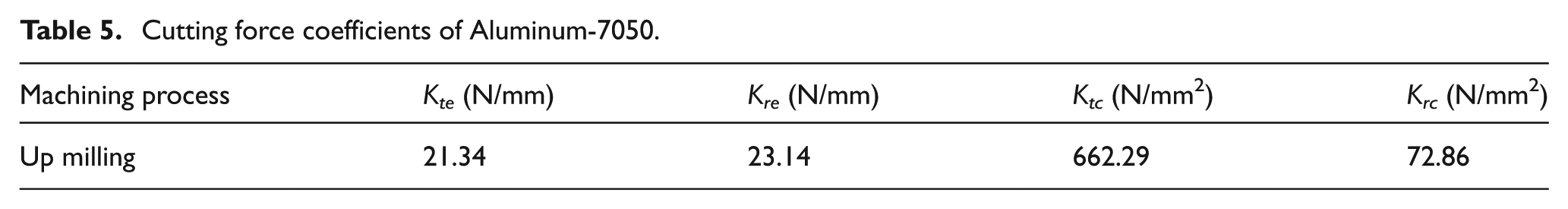
Based on cutting force coefficients, start
Based on the cutting force coefficients, oriented milling coefficient matrix and structural transfer function matrix that have already been calculated, we couple the dynamic model of the spindle-tool system with milling process model and derive the characteristic equation of the closed-loop dynamic milling system latter.
Output layer
After obtaining the transfer function matrix
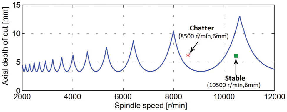
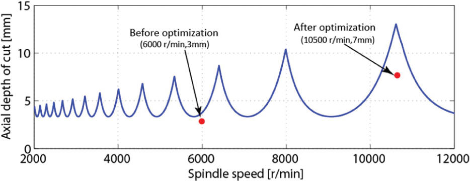
Chatter stability lobe diagram (slot milling).
Two cutting tests were carried out, respectively. The first case is the stable cutting point in Figure 5, corresponding to spindle speed n = 10,500 r/min and depth of cut a = 6 mm. Figure 6 shows the comparison of resultant cutting forces obtained with simulation and measurement. In stable cutting, the waveform of cutting force is similar to sinusoidal waveform and is very regular, with amplitude fluctuating between 0 and 400 N range. In the spectrum of cutting force, the dominant frequency components are tooth passing frequency (ftp) 350 Hz and its harmonics. The simulated cutting force agrees well with experimental results, verifying the accuracy of milling model.
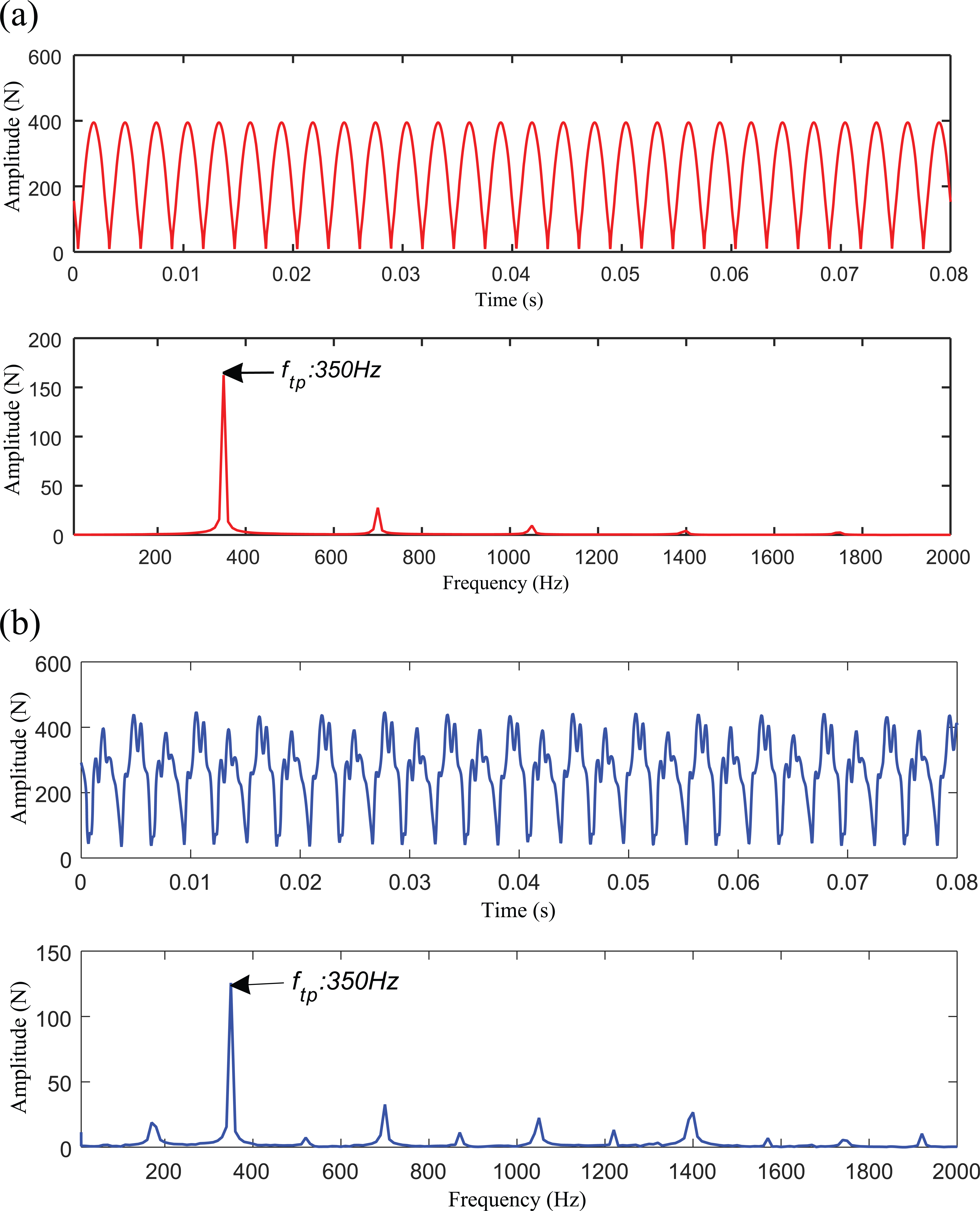
Comparison of cutting forces and spectra of simulation and experiment in stable condition (spindle speed: 10,500 r/min, feed rate: 1500 mm/min, axial depth of cut: 6 mm and slot milling): (a) simulation result and (b) experimental result.
The following is the simulation of relative vibration displacement between tool and workpiece under stable cutting condition, as shown in Figure 7. It can be found that the vibration is small under stable cutting condition and changes in a sinusoidal wave as well.
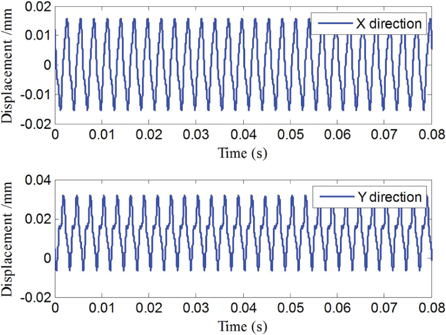
Simulation of relative displacement between tool and workpiece in the stable condition.
In the full immersion slot milling process, down milling and up milling methods exist simultaneously, and the two side walls of groove are down milling surface and up milling surface, respectively. The machined surfaces of both down milling and up milling are simulated, and then compared with experiments under the stable cutting condition.
As is shown in Figure 8, the machined surface is good with roughness value Ra about 1 µm in stable cutting. The surface topography is simulated with the software Cut Pro 9.0®. What’s more, there is no significant distinction of surface quality between down milling and up milling.
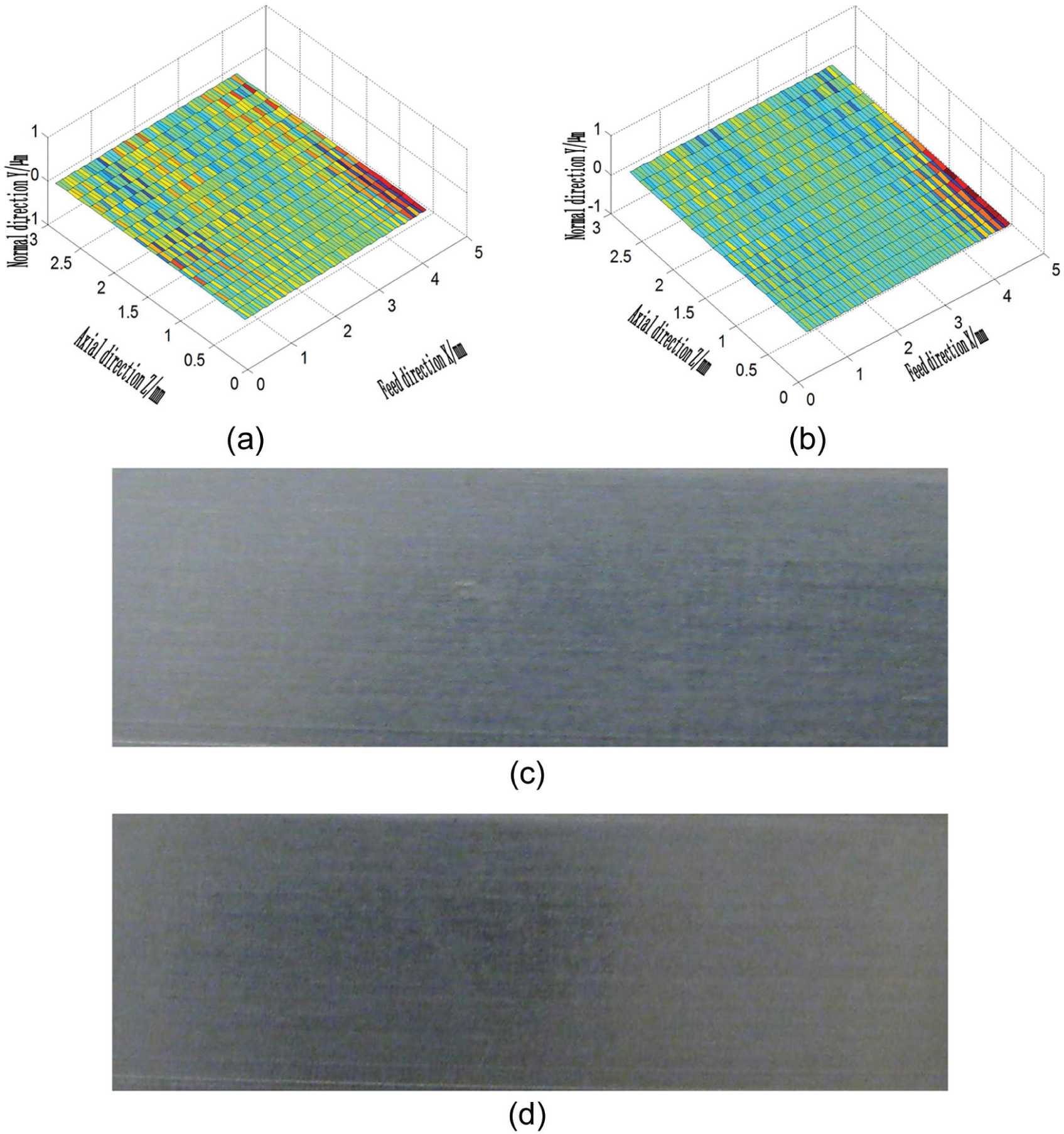
Comparison of machined surface in simulation and experiment in stable condition: (a) simulation of machined surface in down milling, (b) simulation of machined surface in up milling, (c) actual machined surface in down milling and (d) actual machined surface in up milling.
The second case is the cutting point where chatter occurs in Figure 5, corresponding spindle speed n = 8500 r/min and depth of cut a = 6 mm. Figure 9 shows the comparison of resultant cutting forces obtained with simulation and measurement. Compared with stable cutting state, the amplitude of cutting force increases obviously and fluctuates in the range 0∼1000 N. In the spectrum of cutting force, in addition to tooth passing frequency (ftp) 283 Hz and its harmonics, the chatter frequency (fc) of 1300 Hz appears clearly, which is close but not equal to the first-order modal natural frequency of structure. The simulation of cutting force agrees well with the measurement, verifying again the accuracy of high-speed milling process model.
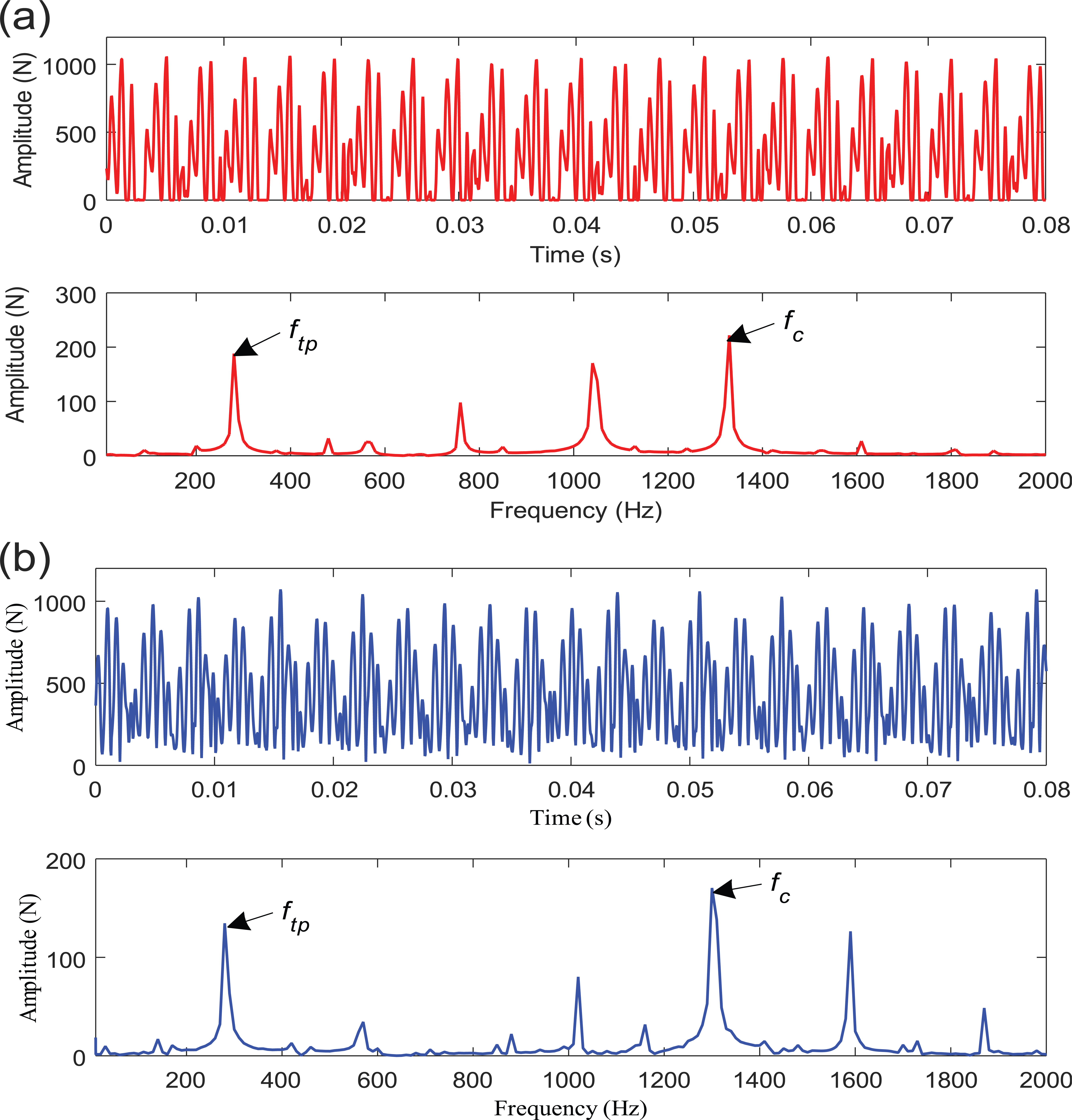
Comparison of cutting force in simulation and experiment under chatter condition (spindle speed: 8500 r/min, feed rate: 1500 mm/min, axial depth of cut: 6 mm and slot milling): (a) simulation results and (b) experimental results.
The following is the simulation of relative vibration between tool and workpiece under chatter condition, as shown in Figure 10. When chatter occurs in machining process, the amplitude of relative vibration between tool and workpiece increases dramatically and the vibration frequency increases as well.
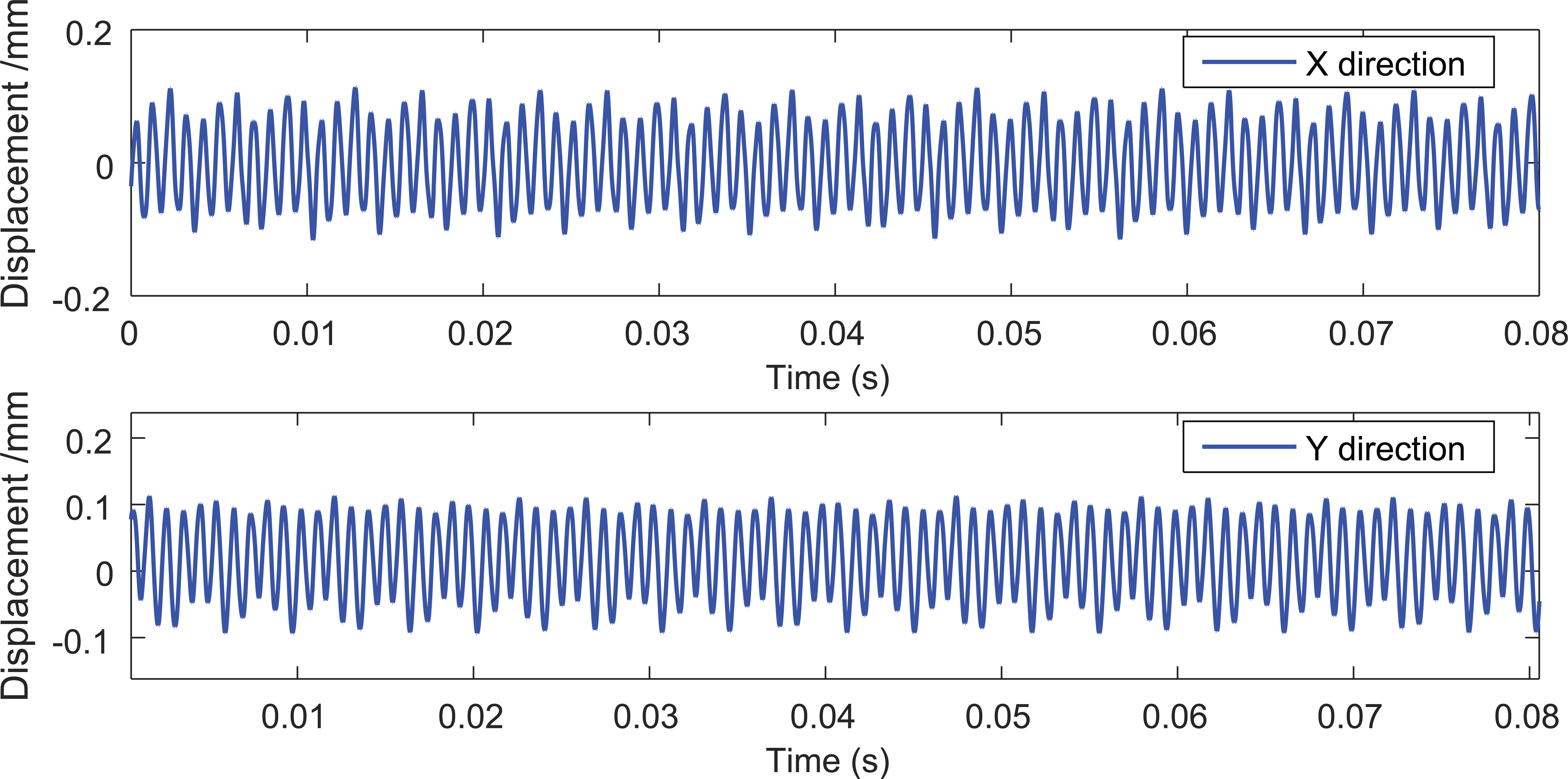
Simulation of relative displacement between tool and workpiece under chatter condition.
The machined surfaces of both down milling and up milling are simulated and then compared with experiments under the chatter cutting condition. As is shown in Figure 11, according to the simulated surface topography with Cut Pro 9.0 in down milling or up milling, large amount of peaks and valleys exist. Due to the effect of chatter, surface quality drops seriously. The roughness value Ra of machined surface in down milling condition is about 15 µm, while in up milling it is about 20 µm.
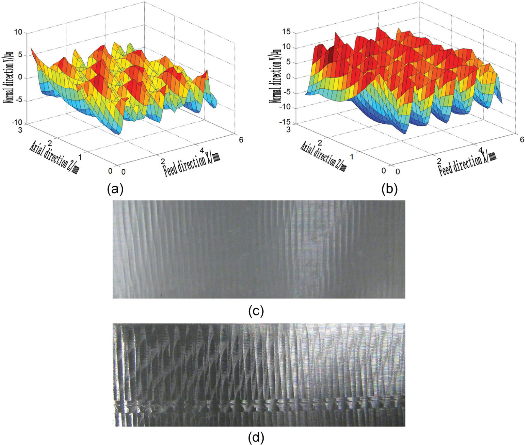
Comparison of machined surface quality between simulation and experiment under chatter condition: (a) simulation of machined surface in down milling, (b) simulation of machined surface in up milling, (c) actual machined surface in down milling and (d) actual machined surface in up milling.
Decision layer
With the initial cutting parameters as shown in Table 4, the cutting state is stable. However, the material remove rate is 60 cm3/min before optimization. According to the stability lobe diagram as shown in Figure 12, the best spindle speed for machining ranges from 10,000 to 11,500 r/min. In order to select reasonable spindle speed and depth of cut, the lower bound of chatter stability lobe diagram and surface finish are taken as constraints, and the maximum MRR is set as the optimization target. Based on the chatter stability lobe diagram and maximum output power of spindle, the optimal results of spindle speed and axial depth of cut are shown in Table 6. After optimization, the spindle speed is 10,500 r/min and axial depth of cut increases to 7.0 mm, and hence the machining efficiency increases about 133%. With the optimized cutting parameters, the surface roughness of the machined workpiece is less than 3.2 µm, which can fulfill the requirement.
The selection of cutting parameters according to lobe diagram.
Comparison of cutting parameters before and after optimization.
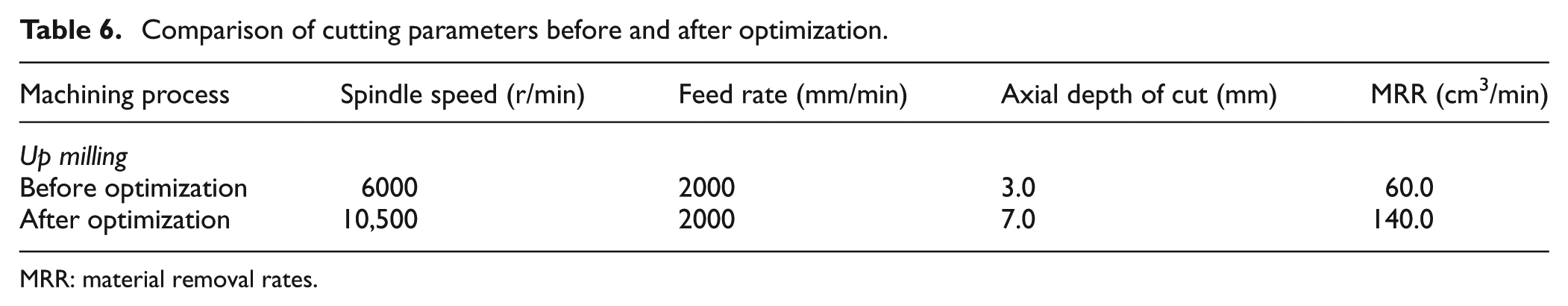
MRR: material removal rates.
Conclusion
In this article, a coupled dynamic model of the high-speed spindle system and machining process is presented. Through analysis of the interaction mechanism between the high-speed spindle system and the machining process, the characteristic equation of the closed-loop dynamic milling system is derived, and then chatter stability lobes and surface topography of machined workpiece are predicted. Based on the process stability and surface quality of workpiece, a cutting parameters selection method is proposed to increase MRR in high-speed machining process. The case study shows that the proper selection of cutting parameters can increase the machining efficiency largely.
Footnotes
Acknowledgements
The authors wish to express their heartfelt gratitude to Professor Yusuf Altintas from Manufacturing Automation Laboratory (MAL), The University of British Columbia, for his support throughout this work. All the experiments of this article were carried out in MAL.
Declaration of Conflicting Interests
The author(s) declared no potential conflicts of interest with respect to the research, authorship and/or publication of this article.
Funding
The author(s) disclosed receipt of the following financial support for the research, authorship, and/or publication of this article: This work is supported by the Alexander von Humboldt Foundation and National Natural Science Foundation of China (No. 51575423, 51421004).