
Abstract
Electro-optical detection systems have been widely utilized in many applications. The pointing accuracy is often seriously affected by static geometric errors. This article analyses the contributions of integrant geometric error sources by means of quaternions, and a parametric model is hence established. As to nonlinear errors, this article further proposes a semi-parametric model that is based on least squares collocation method. Test results demonstrate that both models can improve the pointing accuracy effectively, with latter offering better performance. The estimation variances in azimuth and elevation validation test have been reduced to 0.0014(°)2 and 0.0009 (°)2 from 0.0258(°)2 and 0.0017(°)2, respectively.
Keywords
Introduction
Inertially stabilized platforms (ISPs) have been widely used to maintain its sensor’s orientation in an accurate direction in many applications, such as vehicles, ships, aircrafts and spacecraft.1–4 Electro-optical detection systems (EODSs) including optical imaging sensors and ISPs are utilized to collect targets’ location information, which is of great significance in scientific, military and commercial applications.2,5 In the manufacturing and assembly processes, it is inevitable to introduce errors such as misalignment error, nonperpendicularity and initialization error, which can result in the static pointing error.6,7 As a key technical parameter of the front measuring module, static pointing accuracy significantly affects the target tracking and location. Therefore, it is necessary to model and calibrate these errors to improve the pointing accuracy. 8 At present, there are various approaches to establish the error model, such as Debye–Hückel (D–H) equation4,9 and coordinate transformation (rotation matrix). 10 Since quaternions can visually represent a rotation, 11 this article employs quaternions to analyse integrant errors of EODS for the first time. There are still nonlinear errors that cannot be compensated for by parametric model, such as mechanical deformation and environment factors. It further improves the pointing accuracy by means of semi-parameter model.
Pointing error modelling
The EODS is a servo-controlled system including inner and outer gimbals, which rotate around azimuth and elevation axes, as shown in Figure 1, with the imaging sensor fixed on the inner gimbal. The rotated angles are defined as azimuth and elevation, respectively. Rate gyroscopes are utilized to measure the rotation speed and sense the platform vibration to attenuate the disturbance to the line of sight (LOS).2–5 Proper control algorithm will increase dynamic pointing accuracy in inertial space and hold LOS stationary to obtain clear target images. Position sensors such as optical-electricity encoders or rotary transformers are utilized to obtain the rotation angle, and the spatial pointing direction of LOS can hence be calculated. 1 This article focuses on the geometric errors of EODS without considering dynamic control error.
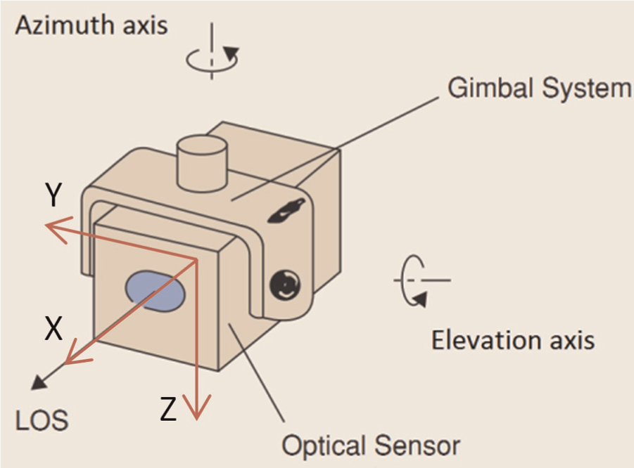
Two-axial gimbal system.
Ideal pointing direction
To facilitate the analysis, the coordinate system is established as shown in Figure 1. At the 0 positions, azimuth axis is the OZ-axis, elevation axis is the OY-axis and the ideal LOS is coincident with OX-axis, which are in accord with the right-hand coordinate system. Furthermore, the rotation angles are defined as shown in Figure 2. The LOS OE rotates R and P around the azimuth (OZ)- and elevation (OY)-axes, respectively, to
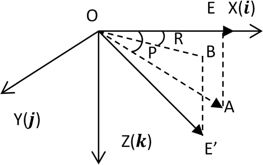
Schematic diagram of rotation angles.
Invented by W.R. Hamilton, quaternions can be used to speed up calculations involving rotations. A quaternion is represented by just four scalars, in contrast to a 3 × 3 rotation matrix that has nine scalar entries.12,13 A unit quaternion is used to denote a rotation.11,14 Assume the rotation around the elevation axis is first analysed, then around the azimuth axis. The rotation quaternions are shown in equations (1) and (2), where the counter-clockwise is positive


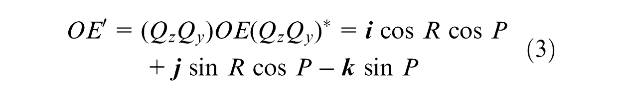
The original vector can be described as
Integrant error analysis
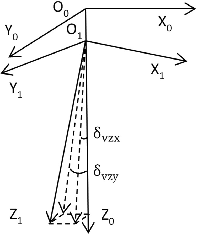
Nonperpendicularity
Ideally, the rotation axes of EODS are perpendicular to each other. However, axis nonperpendicularity may result from the assembling process, with misalignments among azimuth axis, elevation axis and the carrier. For instance, the EODS is fixed on an unmanned aerial vehicle (UAV); if the azimuth axis tilts from the vehicle, although the measurement of EODS is accurate, it will introduce errors to the target location in the whole system. The inclined angular components around OX- and OY-axes are
Azimuth axis nonperpendicularity.
Take the bias around OX-axis as an example; the process is equivalent to rotating
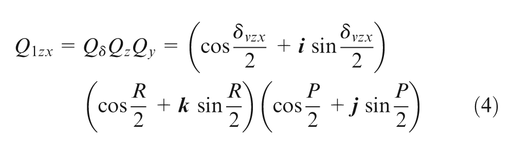
The actual pointing direction is defined as
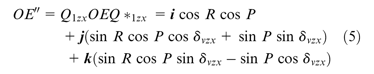
As
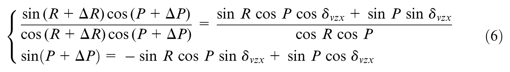
Then
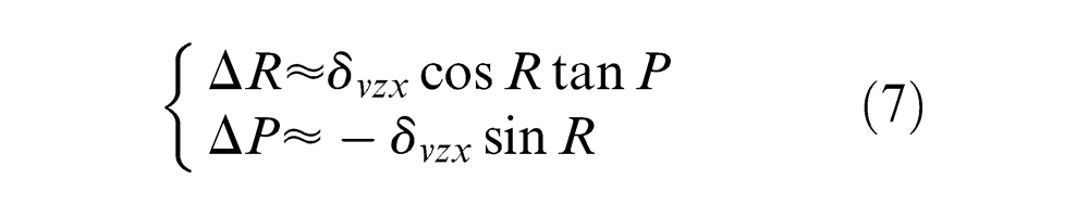
Other nonperpendicularity errors can also be computed in the same way.
Optical axis misalignment and initialization error
In the assembly process, it is also difficult to keep the LOS aligned with OX-axis, which will result in the LOS rotating around OY- and OZ-axes. The inclined angular components are defined as
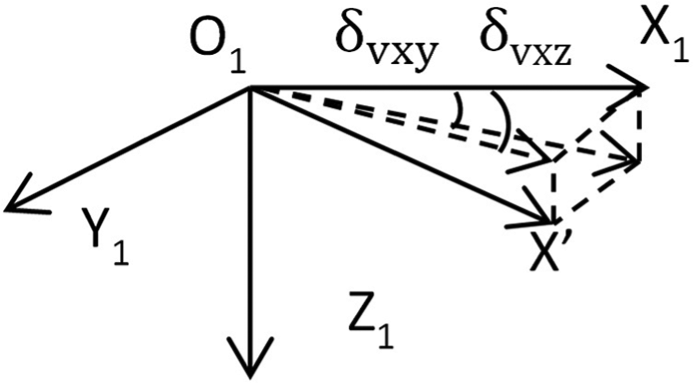
Optical axis misalignment.
Encoder scale error
Adopting the encoder scale error analysis of telescopes in Luck, 15 the error is

where
Rotating shaft error
Bearings define the rotating shaft position and allow the axes to run freely. Wobble and runout in a bearing cause the instantaneous axis of rotation to change and directly result in pointing error.
16
The rotating shaft error is shown in Figure 5, where
Rotating shaft error.
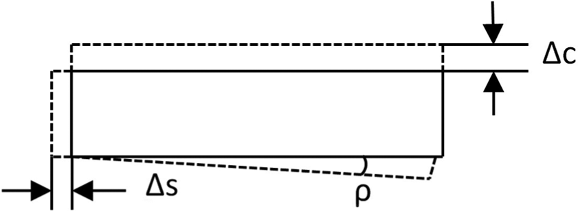
Rotating shaft error will cause the encoder eccentricity, resulting in the indication error. As shown in Figure 6, the dashed line denotes the original position, and the solid line denotes the tilted encoder disc position.
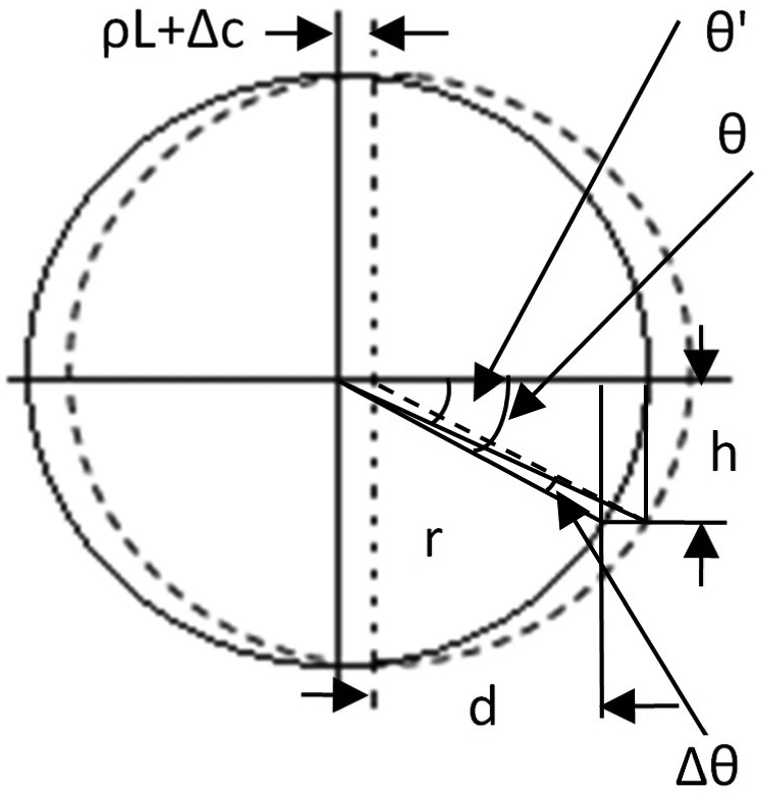
Encoder eccentricity.
It can be shown that

where
As to the azimuth and elevation axes, the slant angles are assumed as
Integrant error summary
According to the above description, the errors are presented in Table 1.
Integrant error summary.
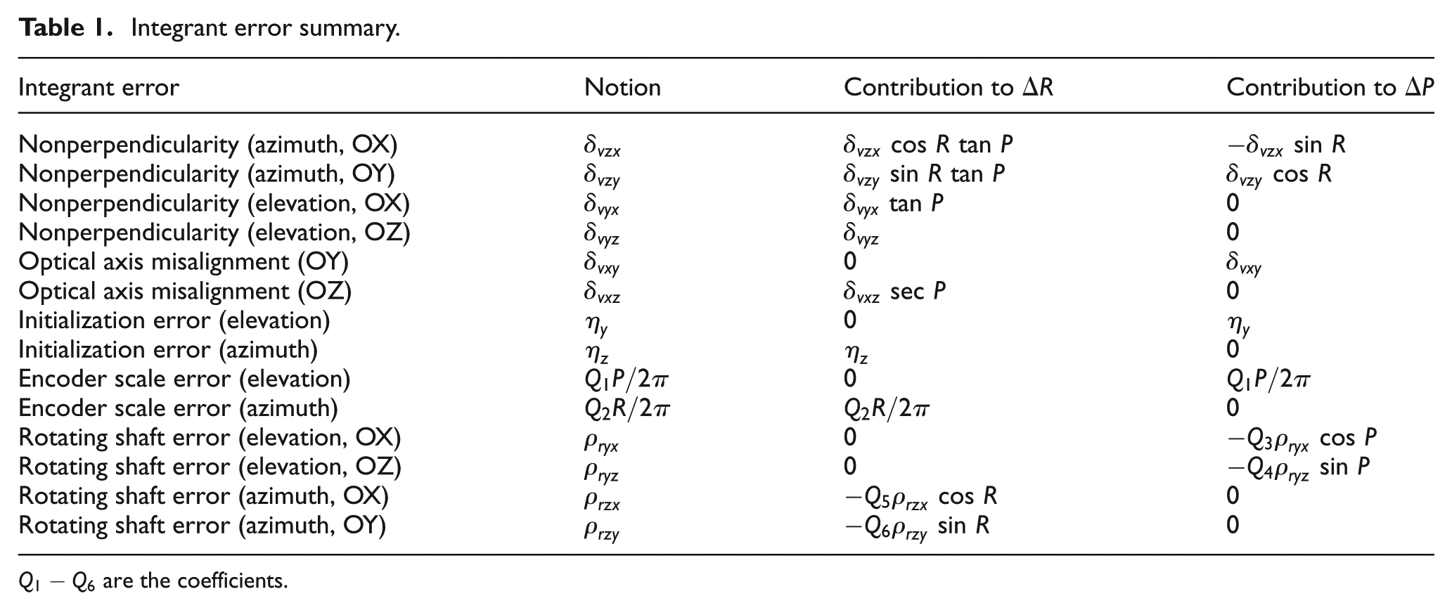
Adding all the contributions, the final integrant error model is hence obtained
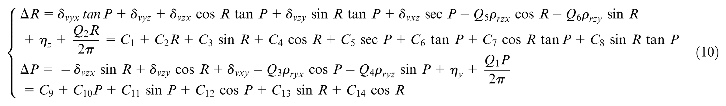
where
Semi-parametric model
The integrant error model presented in equation (10) is based on geometric errors, which is a parametric model. There are still nonlinear errors that are not considered, such as the environment factors including temperature, atmosphere, gravity, wind and vibration.4,5 To improve the pointing accuracy, it is necessary to compensate for these nonlinear errors. Since a semi-parametric model contains both parametric and nonparametric components, it provides a convenient way to analyse nonlinearities and has been widely used.18–20
Least squares collocation
As an estimation method for semi-parametric model, least square collocation has also been widely used. The model can be written as4,18
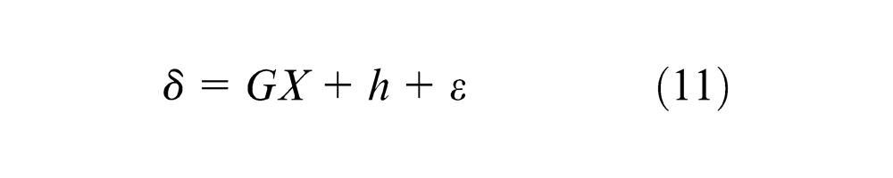
where
According to equation (11), the estimated error of the model is shown as follows
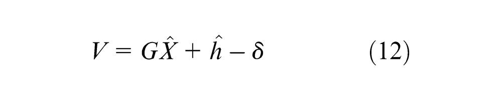
where
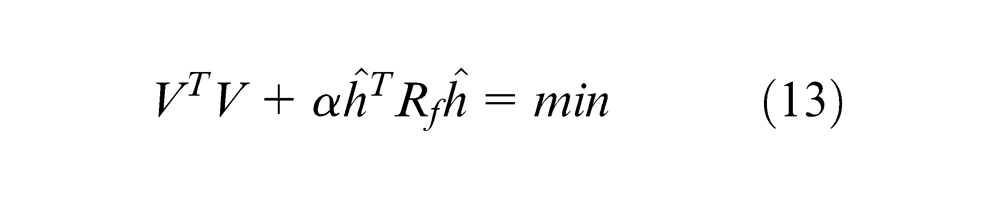
To identify the optimal estimate of equation (12), a commonly used solution is adding a penalty term to standard least squares as shown in equation (13), and relevant derivation is also presented in Hong et al., 4 Sun and Wu 18 and Pan and Sun 21
where
According to Lagrange multiplier rules, the Lagrange function
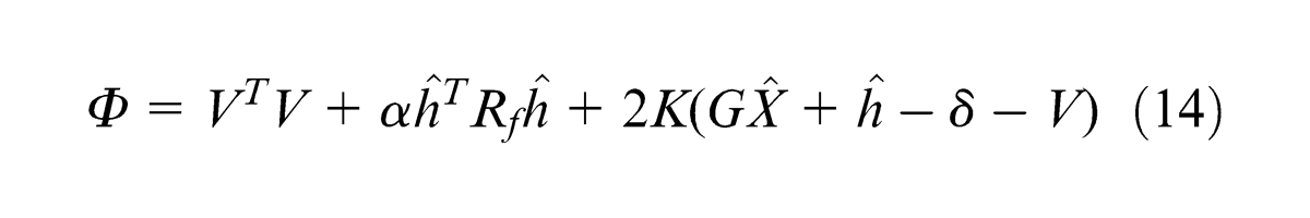
where
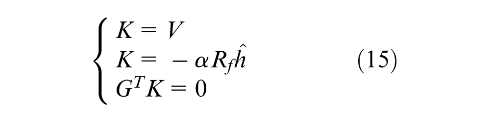
After the elimination of
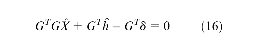
From equations (12) and (15), the below can also be obtained
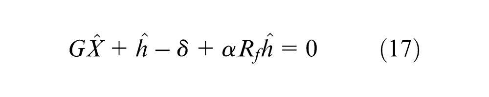
Combining equations (16) and (17), the estimate of
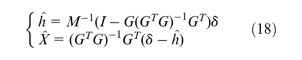
where
Selection of
and
As the smoothing factor,
There are many approaches to choosing the regular matrix
Thus
Test results
The data acquisition system mainly contains a high-precision triaxial turntable, an autocollimator and the EODS. The reflection mirror is fixed on the inner gimbal of EODS. The EODS is fixed on the middle axis of the turntable. The angular range is −20° to 20° for azimuth and −20° to 10° for elevation, with the test apparatus shown in Figure 7. The turntable provides precision rotatory angles, the EODS rotates in the opposite direction and the autocollimator presents the pointing errors.
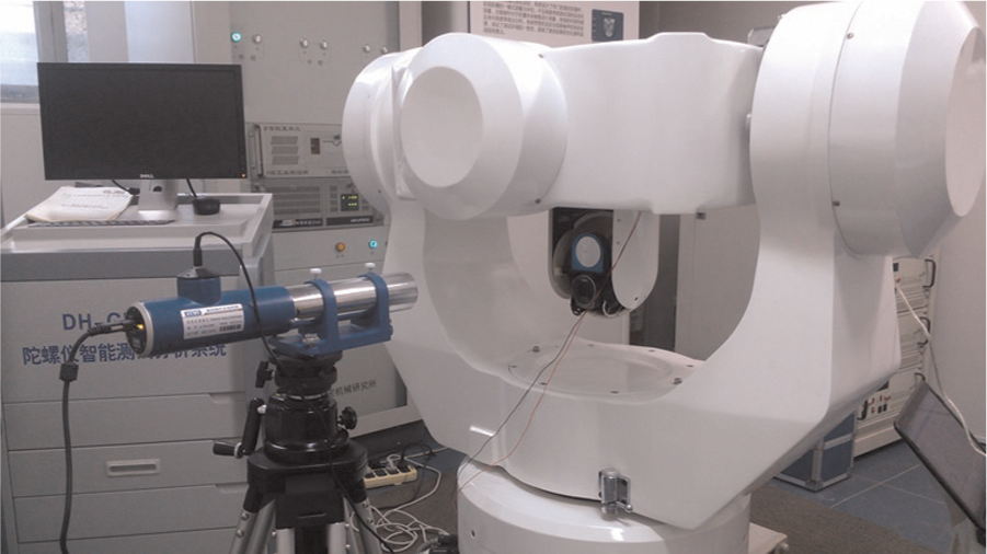
EODS calibration.
Once the systemic errors of the calibration system are known, the compensation results by parametric model presented in equation (10) and semi-parametric model presented in equation (12) are given out in Figure 8 and Table 2 in terms of azimuth and elevation.
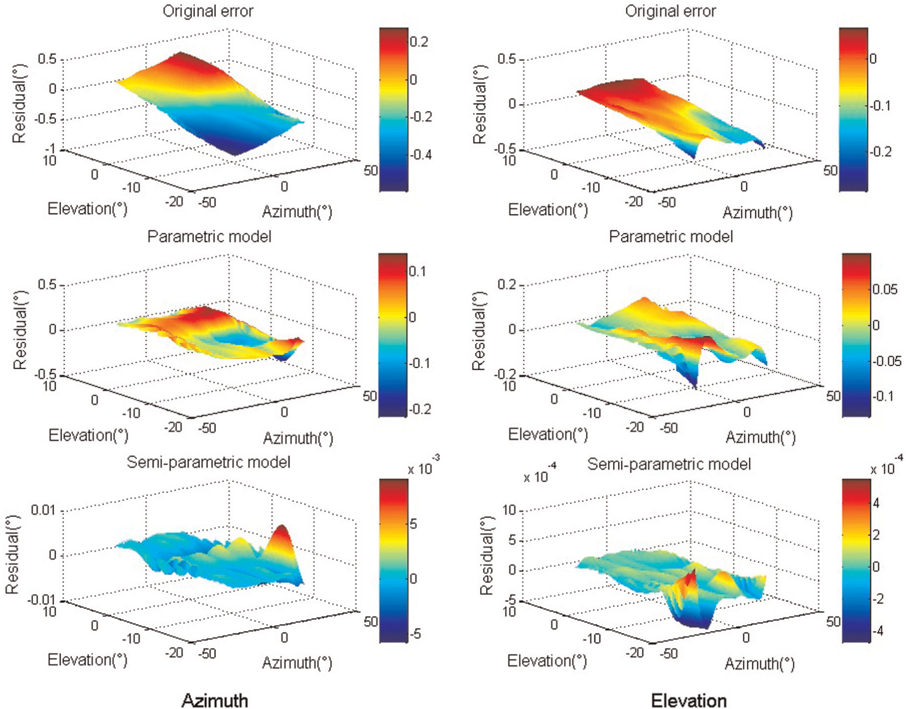
Comparison of compensation results.
Compensation comparison of parametric model and semi-parametric model.
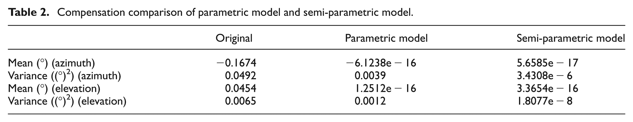
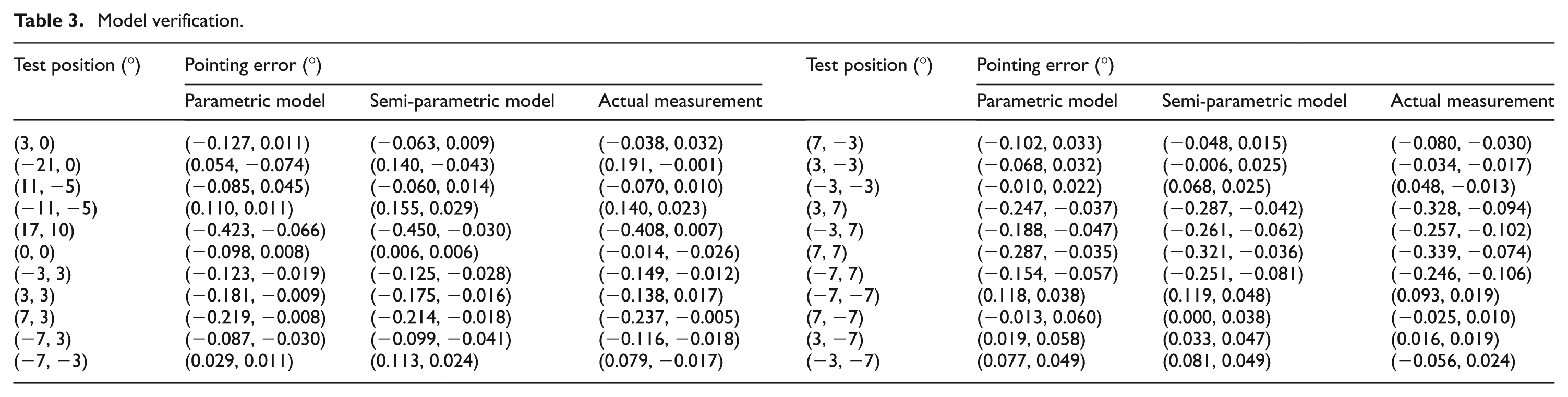
The results demonstrated that the pointing error is effectively compensated. Using the parametric model, the variance in azimuth error has decreased by an order of magnitude, and the elevation error has decreased to 0.0012(°)2 from 0.0065(°)2. In contrast, the semi-parametric model has achieved more significant reductions. From the fitting coefficients, it can be seen that the nonperpendicularity both from azimuth and elevation is the main error source. Meanwhile, to verify the effectiveness of established models still further, another set of data points are acquired. The estimation results by both parametric and semi-parametric model are shown in Table 3 and Figure 9.
Model verification.
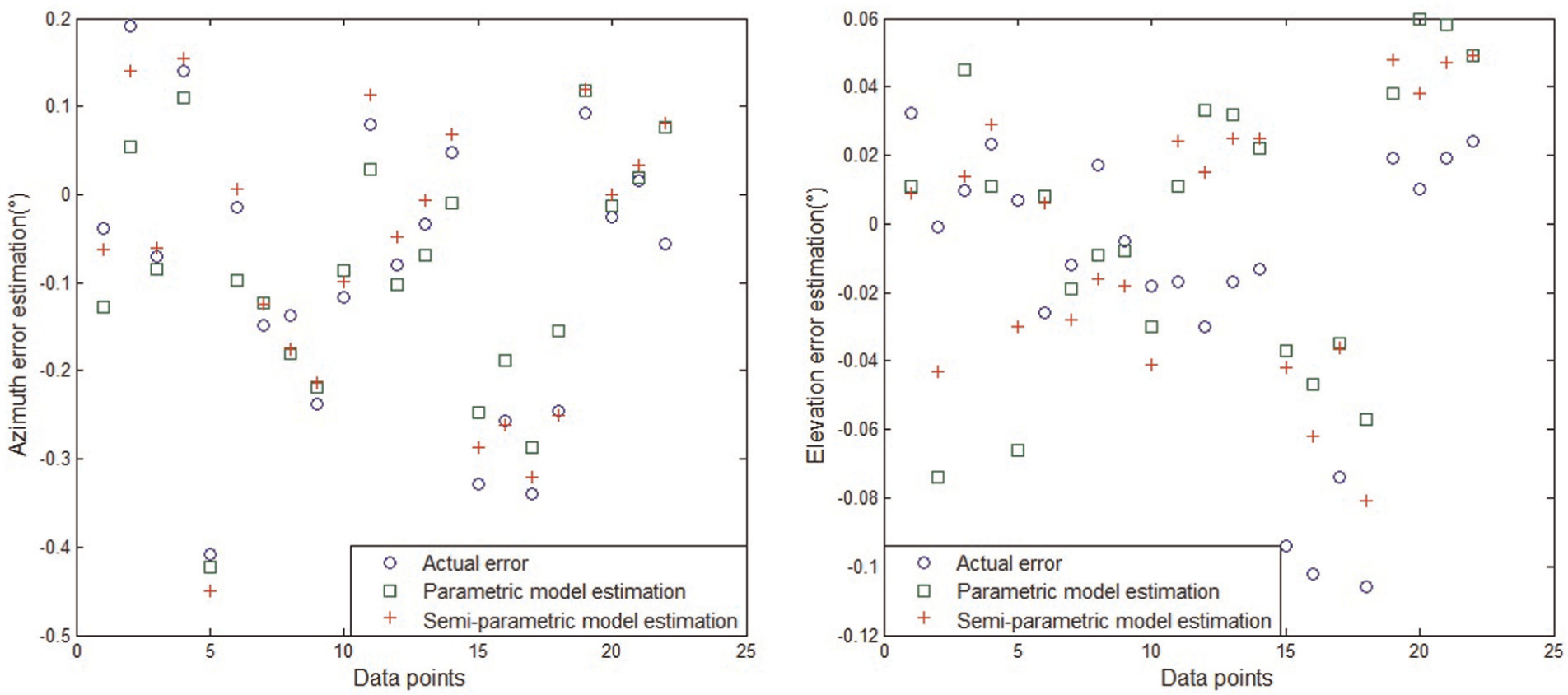
Estimation results.
According to the estimation results, for the azimuth, the variance has decreased from 0.0258(°)2 to 0.0042(°)2 and 0.0014(°)2 by parametric and semi-parametric models, respectively. The mean value reduction is at least by an order of magnitude. For the elevation, the variance has reduced to 0.0016(°)2 and 0.0009(°)2 from the original 0.0017(°)2. Especially, with the semi-parametric model estimated, the absolute value of the pointing residual of azimuth is less than 0.06° except the last point which may have a gross error. All these estimation results indicate that both parametric and semi-parametric models developed in this article can improve the pointing accuracy effectively, and the latter presents better superiority.
Conclusion
With regard to the pointing error of EODS, this article has employed quaternions to analyse contributions from a set of integrant geometric error sources including nonperpendicularity, optical axis misalignment, initialization error, encoder scale error and rotating shaft error. It has hence established the parametric model of pointing error. The fitting coefficient values indicate that nonperpendicularity is the main error source. Test results have shown that the parametric model can compensate for the error effectively, with the variance reduced from 0.0258(°)2 to 0.0042(°)2 for the azimuth. In order to compensate for the nonlinear errors except geometric errors, it has further developed the semi-parametric pointing error model, and the variances in azimuth and elevation have declined to 0.0014(°)2 and 0.0009(°)2 from 0.0258(°)2 and 0.0017(°)2, respectively, which demonstrates that the semi-parametric model is more effective and powerful.
Footnotes
Appendix 1
Declaration of Conflicting Interests
The author(s) declared no potential conflicts of interest with respect to the research, authorship, and/or publication of this article.
Funding
The author(s) disclosed receipt of the following financial support for the research, authorship, and/or publication of this article: The work was supported by Support Program of National Ministry of Education of China (No. 625010110) and National Natural Science Foundation of China (No. 61179043). It was also supported by China Scholarship Council.