
Abstract
This article investigates modeling and calibration issues that are associated with inertially stabilized platforms to achieve accurate pointing. In modeling part, the Denavit–Hartenberg notation is used to perform an error analysis of the kinematics of inertially stabilized platforms. A physical model is then established to illustrate the effects of geometric errors that are caused by imprecision in the manufacturing and assembly processes on the pointing accuracy of inertially stabilized platforms. In the calibration part, an improved hybrid model denoted as the semi-parametric regression model is developed to compensate for remaining nonlinear errors. With applications to a two-degree-of-freedom miniature inertially stabilized platform, semi-parametric regression model is shown to outperform physical model substantially in all cases. The experimental results also indicate that the proposed semi-parametric regression model eliminates both the geometric and nonlinear errors, and that the pointing accuracy of miniature inertially stabilized platform significantly improves after compensation.
Keywords
Introduction
Inertially stabilized platforms (ISPs) are routinely used on vehicles, ships, aircraft, and spacecraft for diverse missions such as aerial photography, 1 battle reconnaissance, 2 antenna stabilization, and missile guidance. 3 ISPs’ control systems require high-performance pointing direction to achieve accurate target acquisition, tracking, and positioning. However, during the manufacturing and assembly processes, the actual pointing direction of ISP is not the indicated direction due to the influence of various error sources, such as bias (i.e. relatively constant), no uniformity (i.e. variable but repeatable), and random components. 4 Therefore, modeling and calibration techniques that are appropriate for determining the terms of error sources and improving the pointing accuracy are necessary.
To estimate and compensate for the errors of ISPs during machining processes, a number of calibration techniques were investigated by various studies. These techniques can be categorized into two main methodologies. The first method is based on a numerical analysis of the pointing data, wherein a numerical mathematical model explains the differences between the actual and the indicated pointing direction. Several numerical models, such as global function model 5 and extended interpolation model, 6 are developed to compensate for the pointing errors of large two-degree-of-freedom telescopes. Because most of these errors are repeatable, these models are reasonably effective. However, the parameters of these models cannot be attributed to the error sources easily without considering physical relationships. 7 The second approach is based on the analysis of error sources during machining processes, which involves identifying the physical relationships of pointing errors and developing a physical mathematical model using a kinematic method. As noted by Ramesh and Mannan,8,9 sources of inaccuracy in precision machines include geometric errors, thermal errors, cutting force-included errors, servo-control errors, and other nonlinear errors. Geometric errors that reportedly account for 40%–70% of the total errors are repeatable and eliminated easily, and the others, especially the nonlinear errors, are difficult to deal with. Jerome and Arthur 10 and Meeks 11 analyzed the pointing accuracy of a precision gimbaled pointing system for ISPs. The authors focused particularly on geometric error sources that were induced by inaccuracy of transducer, misalignment of base, runout of gimbal bearings, nonperpendicularity and nonorthogonality of gimbal axes, and servo-control errors. Additionally, a physical mathematical model is also developed to address those geometric errors. Keitzer et al. 12 and Kimbrell et al. 13 expanded Jerome and Meeks’ study by exploring the analytical form of geometric errors and adding arbitrary polynomial and harmonic terms to the physical model (PM). However, the extra terms cannot compensate for residual nonlinear errors that remained after developing a PM based on geometric terms. To bridge the gap between the numerical model and the PM without any drawbacks, a hybrid model is required when both geometric errors and nonlinear errors need to be compensated completely.
Offline modeling and online calibration issues are investigated in this article, and a semi-parametric regression model (SPRM) is developed to produce accurate pointing signals. The proposed method has several advantages over other approaches:
A PM that is based on the comprehensive analysis of error sources and kinematic modeling with the Denavit–Hartenberg (D-H) notation was established to illustrate the effects of geometric errors on the pointing accuracy of ISPs.
An improved hybrid offline model called SPRM was developed to compensate for remaining nonlinear errors.
A testing procedure for error compensation was achieved using the proposed method with applications in a two-degree-of-freedom miniature ISP, which resulted in significantly improved pointing accuracy.
The remainder of this article is organized as follows: Section “System configuration and error analysis” demonstrates the ISP configuration, the definition, and the major sources of pointing errors. Section “Kinematic modeling with the D-H notation” describes a PM of the kinematics of ISP, which is based on the illustration of the transformation matrixes between eight different coordinate systems. In section “Semi-parametric regression algorithm,” an improved hybrid model is developed. The proposed method primarily aims to bridge the gap between the numerical model and the PM without any drawbacks. In section “Experiments,” applications to a two-degree-of-freedom miniature ISP are introduced, and extensive experiments are conducted to verify the effectiveness of the proposed method. Section “Conclusion” provides the conclusion.
System configuration and error analysis
Figure 1 illustrates the essential components of a typical ISP, 14 namely, optical imaging sensors, an electromechanical assembly, a servo-control system, and several auxiliary equipment.
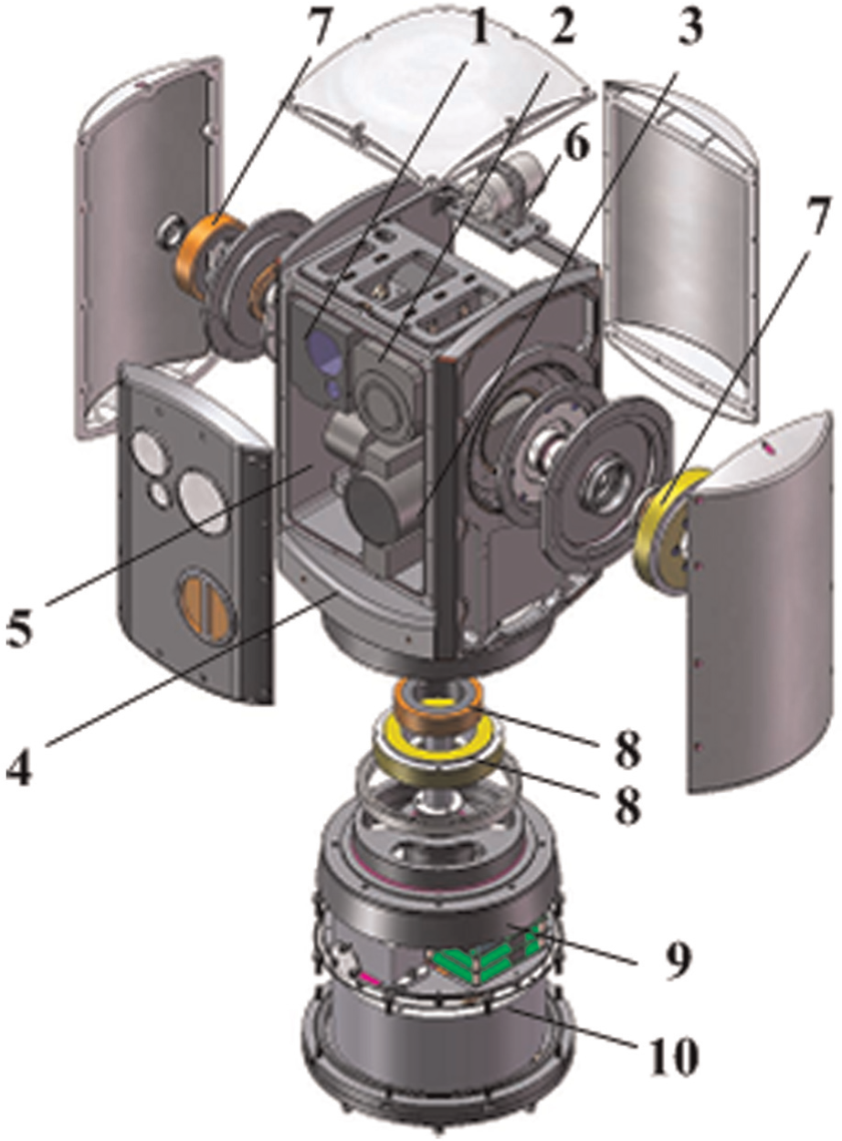
Configuration of a typical ISP (1: laser range finder; 2: visible spectrum camera; 3: infrared camera; 4: outer gimbal rotating about azimuth; 5: inner gimbal rotating about elevation; 6: gyroscope; 7: bearing and motor of outer gimbal; 8: bearing and motor of inner gimbal; 9: target tracker; 10: the servo-control system).
As shown, optical imaging sensors, such as laser range finder, visible spectrum camera, and infrared camera, collect image information about targets or target regions. Controlling the sensors’ line of sight (LOS) can achieve accurate pointing. The electromechanical assembly includes inner and outer gimbals, which are rotated in azimuth and elevation, respectively. The assembly provides a mechanical interface between the optical imaging sensors and the base. The performance of the electromechanical assembly is ultimately determined by the servo-control system, which has at least three functions, namely, stabilizing the sensors’ LOS to produce a high-quality image, tracking to maintain the target within the sensors’ field of view, and measuring the pointing angles to determine the location of the target in an appropriate coordinate system. Several auxiliary equipments that are mounted on the assembly are also required in most ISPs. These equipments include gyroscopes, suspension elements such as bearings, actuators such as motors, relative motion transducers such as encoders, and target trackers.
Pointing errors illustrate the ISPs’ accuracy according to the differences between the actual and indicated pointing direction. As shown in Figure 2, the vector of pointing errors15,16 is given as
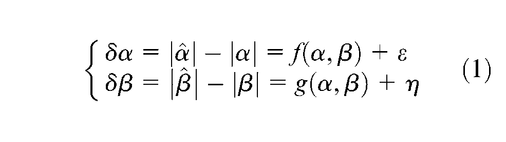
where
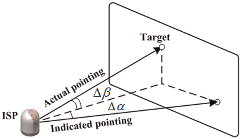
Definition of the pointing error for ISPs.
In any real ISP system, optical, electrical, and mechanical inaccuracies17–19 as well as geometric and nonlinear errors will cause pointing errors. As shown in Figure 3, the major error sources are as follows:
Consistency and distance errors of the optical imaging sensors.
Geometric errors of the electromechanical assembly.
Stabilized and tracing errors of the servo-control system.
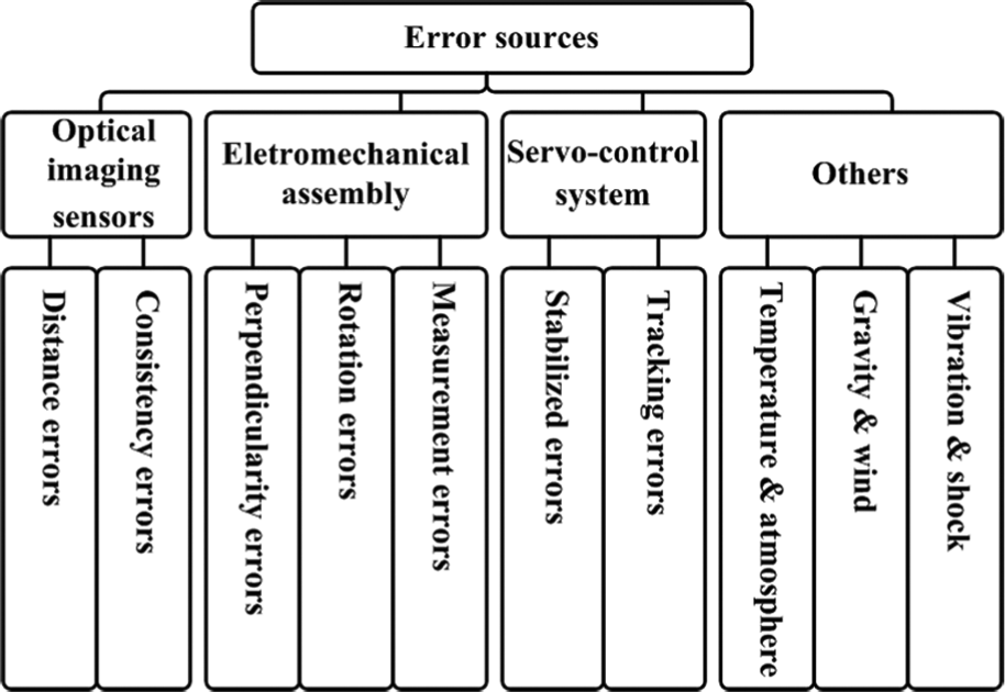
Analysis of the error sources for ISPs.
When optical imaging sensors are mounted on the inner gimbal, misalignment between the optical axis of sensors causes consistency error. When the laser range finder is pointing at the target, distance error also occurs due to measurement inaccuracy.
In an ideal condition, the optical axis, elevation axis, and azimuth axis of an electromechanical assembly are three orthogonal axes in the case of zero elevation. However, in the manufacturing, installation, and operation processes, at least three errors occurred, namely, perpendicularity error due to the nonorthogonal gimbal axes, rotation error due to the fact that relative motion does not remain constant, and measurement error due to the offset and inaccuracy of the encoder.
Most ISP servo-control systems use an inner stabilization loop and outer tracking loop. The former compensates for disturbances and minimizes unnecessary motion of the electromechanical assembly. The latter ensures that the sensors’ LOS remains pointed toward the target. Servo-control errors consist of stabilized and tracking errors that are primarily due to offsets, drift, coulomb friction, and backlash of the auxiliary equipment.
Aside from the given errors, nonlinear errors exist due to environmental factors such as temperature, atmosphere, gravity, wind, vibration, and shock. These errors cannot be demonstrated by a PM and are described only in a statistical manner.
Kinematic modeling with the D-H notation
Reference system definition
The D-H notation 20 is employed to solve the kinematic problem of ISPs that were described in section “System configuration and error analysis,” and a schematic illustration of the coordinate systems is presented in Figure 4. To demonstrate the error sources easily, the base is assigned to the coordinate system (XYZ)0, and the other coordinate systems (XYZ)1 to (XYZ)7 are established appropriately relative to the other rigid bodies. Based on the coordinate transformation matrix, any coordinate system can ultimately be transferred to the base.
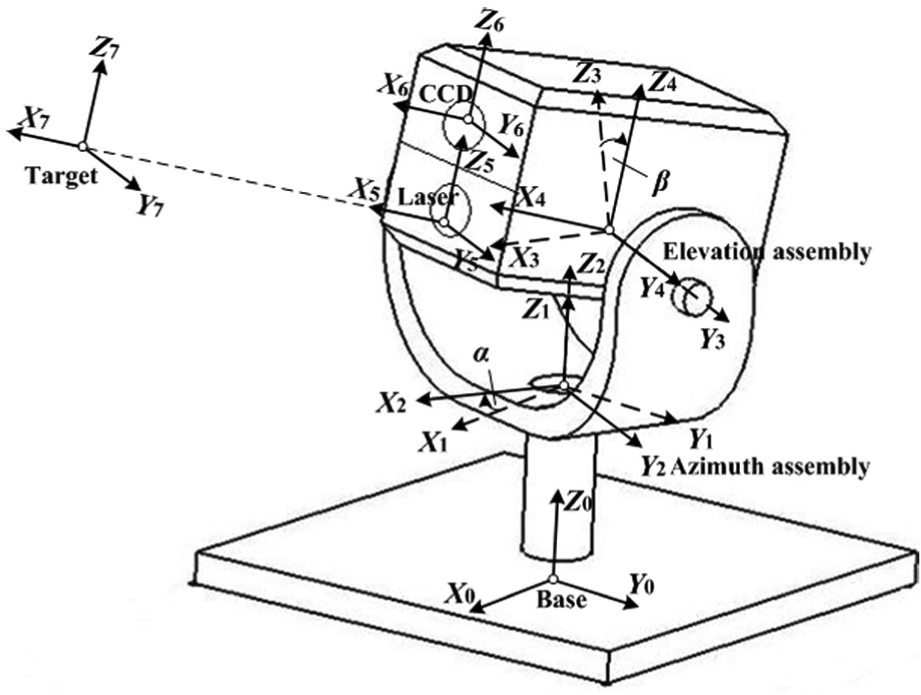
Schematic of the coordinate systems for ISPs.
The D-H notation defines the operating theory of the homogeneous transformation matrix (HTM)21–23 to illustrate the relationship between two neighboring coordinate systems. For example, the coordinate systems (XYZ) i and (XYZ) j are independent coordinates that are fixed on different rigid bodies, that is

where
In an ideal case, if the coordinate system is rotated by an angle a about the x-axis, then the required matrix is given by
Similarly, the matrices of coordinate system after rotating by b and c about the y-axis and z-axis, respectively, are as follows
Transformation of the coordinate systems
With the definition of HTM, the position vector of the target

where
In the following analysis, each HTM will be discussed in detail. The error sources of each rigid body can then be obtained. For illustration purposes, the sequence is considered as optical axis errors, elevation axis errors, and azimuth axis errors.
Optical axis errors
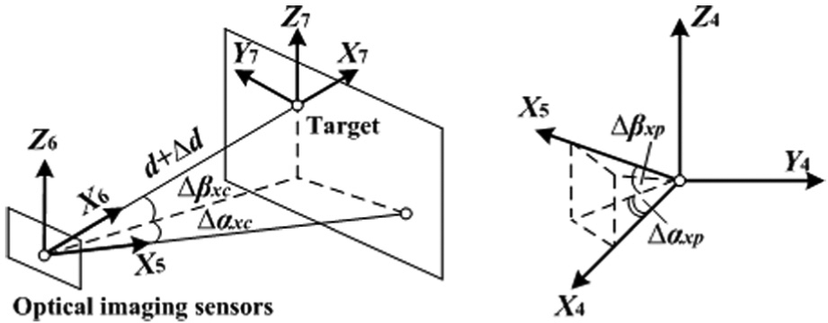
As shown in Figure 5(a), the coordinate system (XYZ)7 is fixed on the target, and the coordinate system (XYZ)6 is fixed on the laser range finder with x-axis pointing at the target. The HTM for transforming coordinates from (XYZ)7 to (XYZ)6 can be expressed as
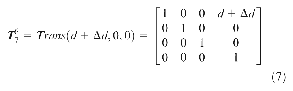
where d is the ideal distance between the target and the ISP, and Δd is the distance error due to the measurement inaccuracy of the laser range finder.
Relationships among optical axis errors: (a) consistency and distance errors of the optical axis and (b) perpendicularity errors of the optical axis.
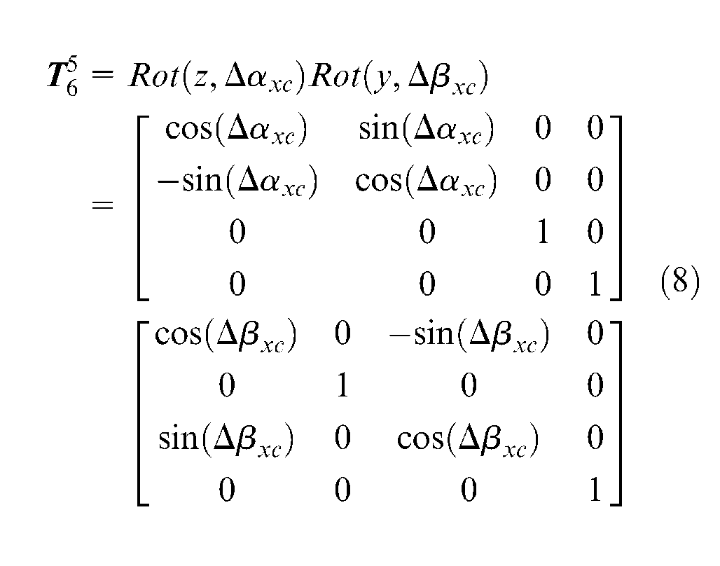
Meanwhile, the coordinate system (XYZ)5 is fixed on the infrared camera, and misalignment of optical axis of the sensors causes additional pointing errors, namely, consistency errors that are determined by two angle errors (Δαxc, in azimuth direction; Δβxc, in elevation direction). The HTM for transforming coordinates from (XYZ)6 to (XYZ)5 can then be expressed as
As shown in Figure 5(b), the coordinate system (XYZ)4 is fixed on the inner gimbal with rotating around elevation axis. When optical imaging sensors are mounted on the inner gimbal, perpendicularity errors occur due to nonorthogonality of the optical axis. These errors are also present in other consecutive gimbal axes. The HTM for transforming coordinates from (XYZ)5 to (XYZ)4 can then be expressed as
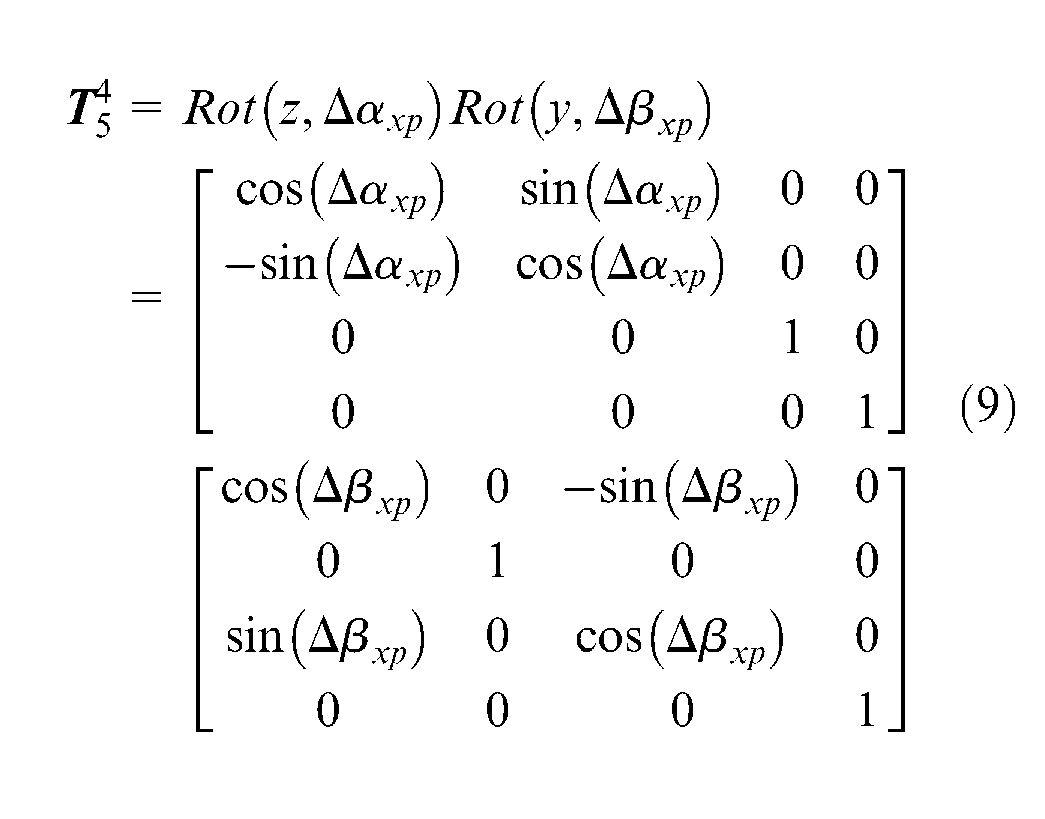
where Δαxp and Δβxp are perpendicularity errors of optical axis in the azimuth and elevation directions, respectively.
Elevation axis errors
As shown in Figure 6(a), the coordinate system (XYZ)3 is fixed on the inner gimbal in the original place without rotating around the elevation axis. Because relative motion exists between (XYZ)4 and (XYZ)3, the angle is indicated by the encoder, whose measurement is given as β+Δβ, where β is the ideal elevation angle and Δβ is the measurement error of the elevation encoder. Considering that the plane does not remain constant due to the bearing parts, rotation errors that can be defined by two angle errors (Δγyr, in the roll direction; Δαyr, in the azimuth direction) also exist.
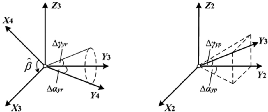
Relationships among elevation axis errors: (a) rotation and measurement errors of the elevation axis and (b) perpendicularity errors of the elevation axis.
The HTM for transforming coordinates from (XYZ)4 to (XYZ)3 can then be expressed as
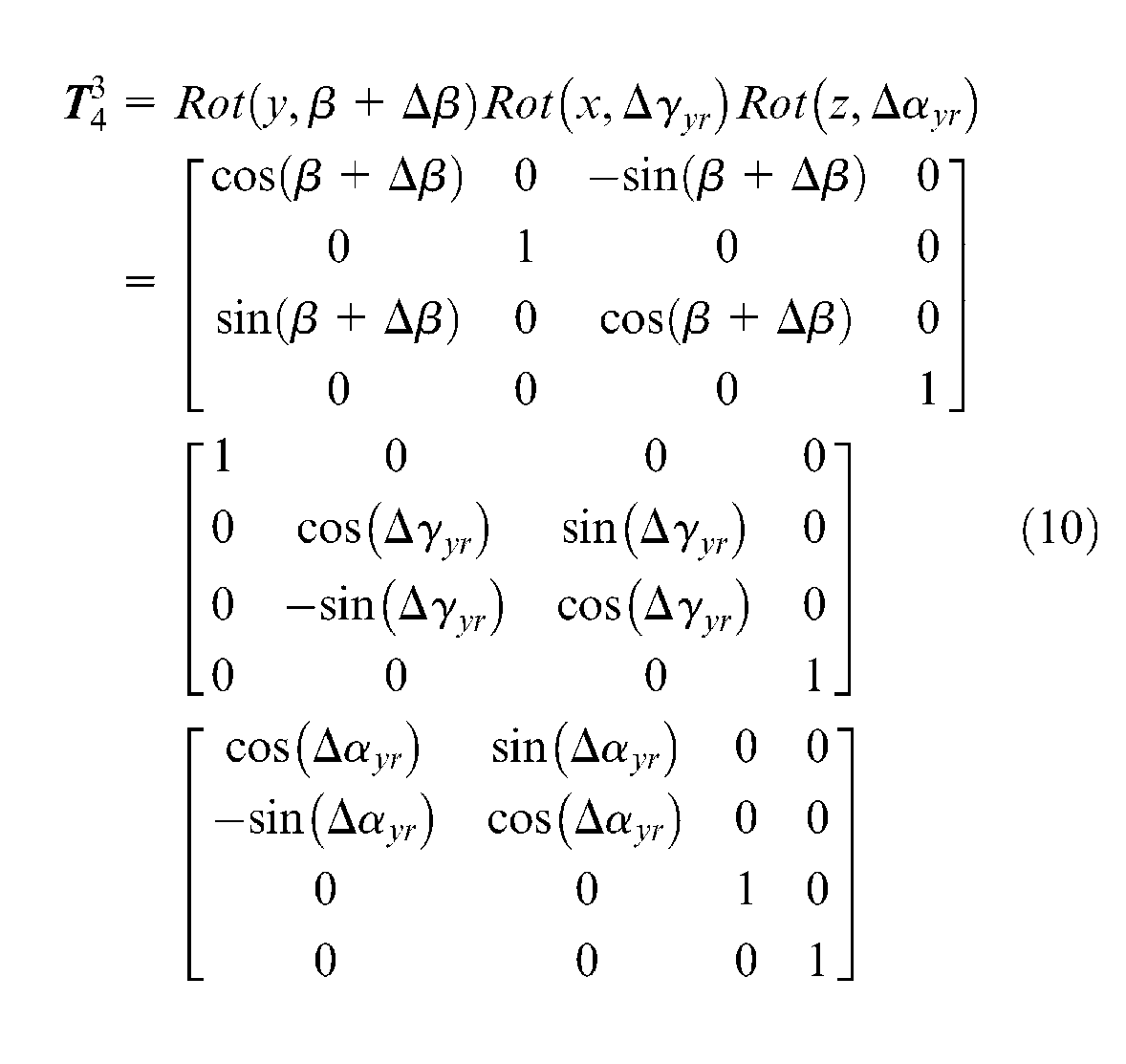
Due to nonorthogonality of the elevation axis, as shown in Figure 6(b), perpendicularity errors, which can be determined by two angle errors (Δγyp, in roll direction; Δαyp, in azimuth direction), are present. The HTM for transforming coordinates from (XYZ)3 to (XYZ)2 can then be expressed as
Azimuth axis errors
Similar to elevation axis, the HTMs of azimuth axis are derived, as shown in Figure 7.
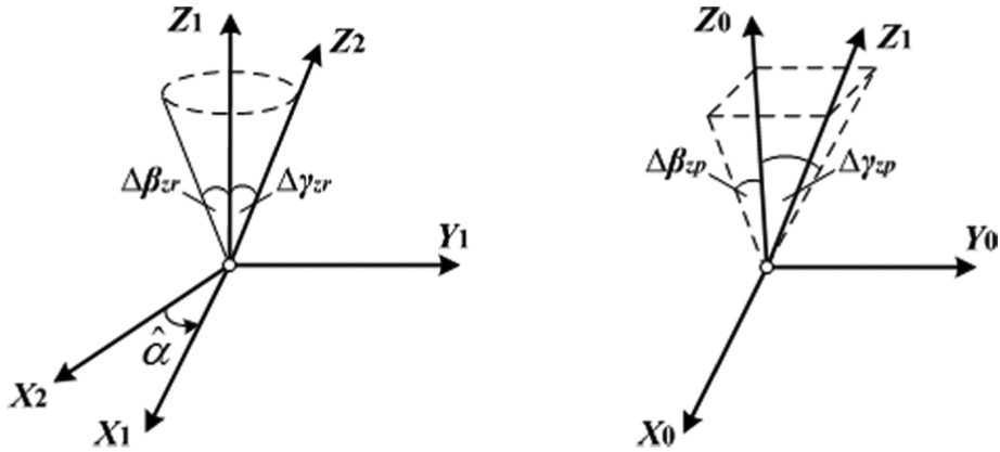
Relationships among azimuth axis errors: (a) rotation and measurement errors of the azimuth axis and (b) perpendicularity errors of the azimuth axis.
The HTM for transforming coordinates from (XYZ)2 to (XYZ)0 is then obtained by
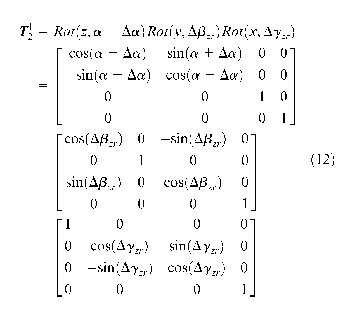
where α is the ideal azimuth angle and Δα is the measurement error of the azimuth encoder. Δβzr and Δγzr are rotation errors of the azimuth axis in elevation and roll direction, respectively
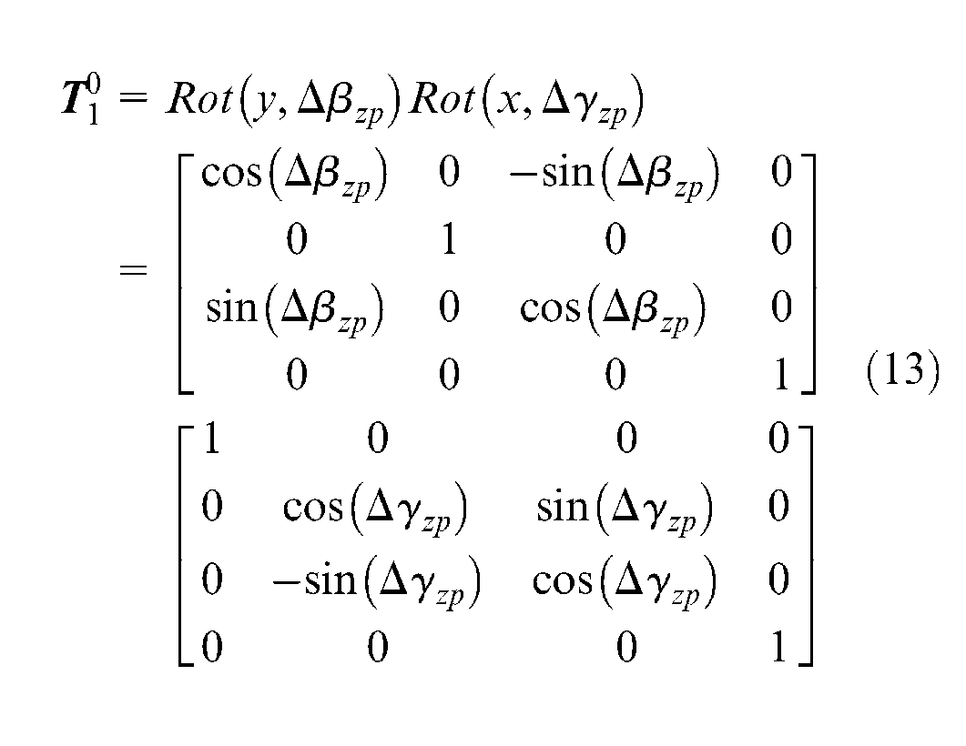
where Δβzp and Δγzp are perpendicularity errors of the azimuth axis in elevation and roll direction, respectively.
Development of the PM
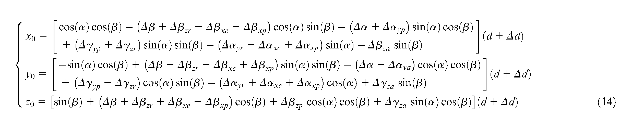
With the abovementioned HTMs, position vector

Substituting equations (7)–(13) into equation (6) with small-angle approximations yields equation (14)
Using the relationship between the rectangular coordinates form and the spherical coordinates form, the following is obtained
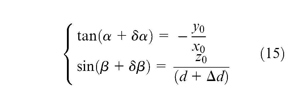
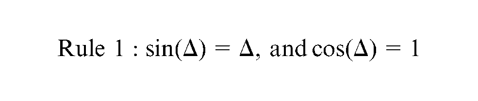
By considering the small-angle approximations, equation (15) can be rewritten as
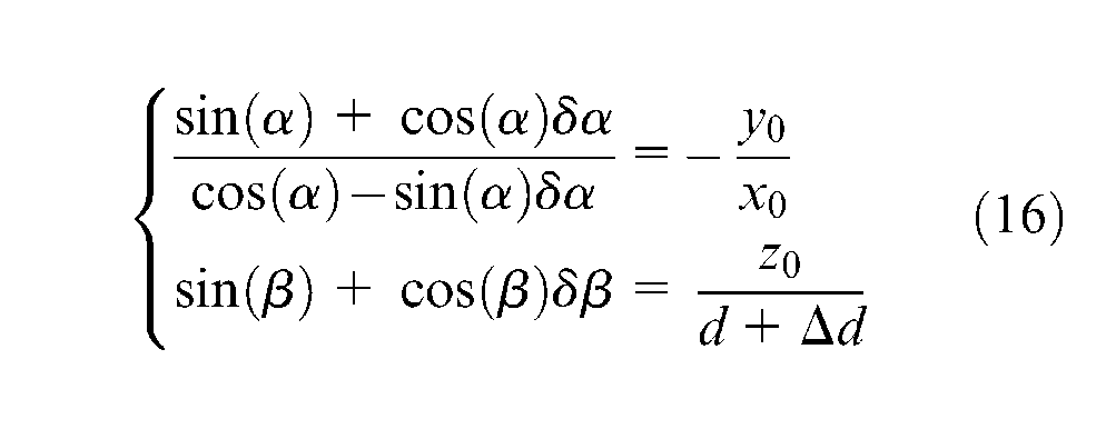
By substituting equation (14) into equation (16) and equalizing the same parts on both sides, the PM of pointing errors was developed
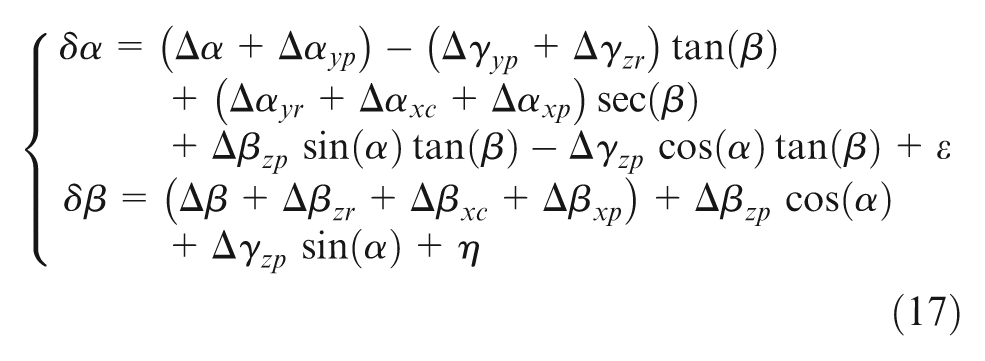
Inspection reveals that equation (17) can be rewritten as a simplified form
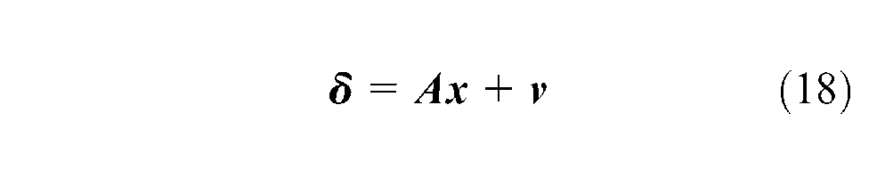
where
Semi-parametric regression algorithm
This section develops a hybrid model based on the PM. This hybrid model is called SPRM and is more suitable for dealing with pointing errors from both geometric and nonlinear aspects.
SPRM
Imprecision in the manufacturing and assembly processes results in complicated effects of error sources on the pointing accuracy of ISP. Therefore, the PM that was established in section “Kinematic modeling with the D-H notation” is unable to take all the cases into consideration. The PM also has the following unavoidable drawbacks:
In the theoretical analysis of error sources, only the major errors, such as geometric errors, are given empirical consideration by the PM. Minor errors that were introduced by environment factors such as temperature, atmosphere, gravity, wind, vibration, and shock are ignored. These nonlinear errors have complicated statistical characteristics and cannot be compensated appropriately by the PM.
In the kinematic modeling of error sources, the small-angle approximations are employed to convert the nonlinear equation (6) in linearization. Numerical errors are introduced in this process. Ignoring minor numerical errors does not influence the estimated values of the PM parameters, whereas major numerical errors exert significant influence on parameter estimation and may result in a false conclusion.
In obtaining the observed pointing errors, the experimental equipment introduces a number of measurement errors. Ordinarily, several crude iterations may be executed to reduce these errors, but errors are unavoidable, especially in the real experimental setup.
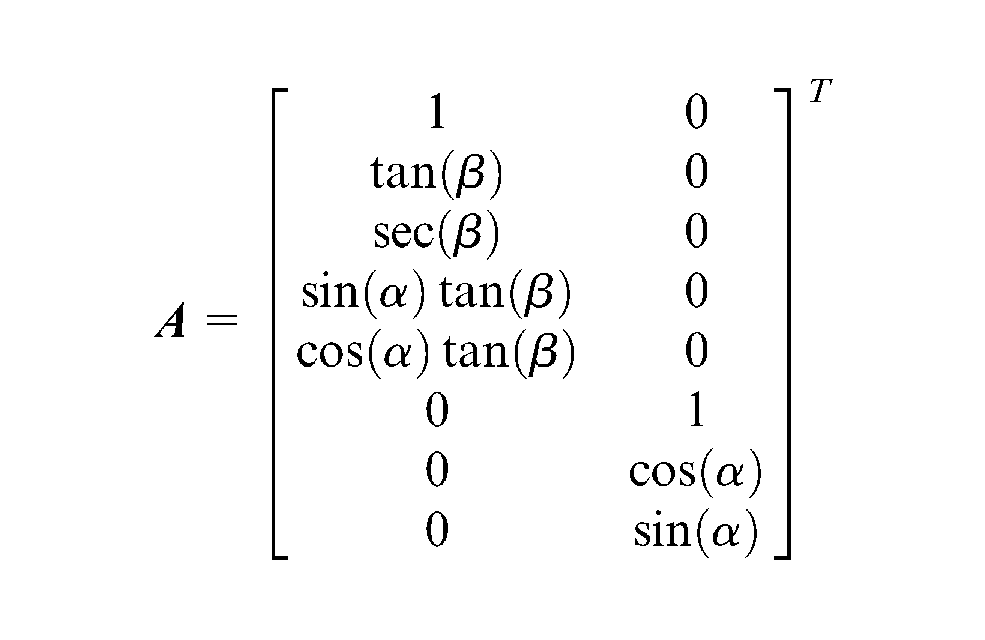
To solve the abovementioned problems, an alternative method can handle the residual nonlinear errors to achieve higher pointing accuracy. Hence, an additional term is added to the PM, as shown in equation (18), which can be rewritten as
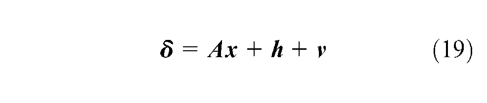
where
Partial least squares estimation
Numerous methods are used to identify the parameters of SPRM, such as partial spline estimation, 24 ridge estimation, 25 and partial least squares (PLS) estimation. 26 In the following, PLS is employed to select the appropriate parameters for SPRM. According to equation (19), the estimated error equation can be shown as

where

where
where
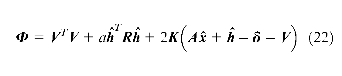
With the first and third items of equation (23), equation (20) can be rewritten as

Substituting equations (20) and (23) into equation (24) yields
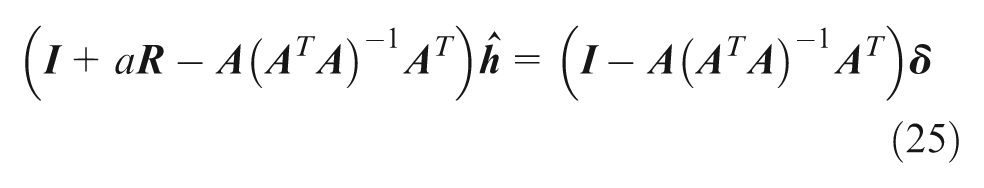
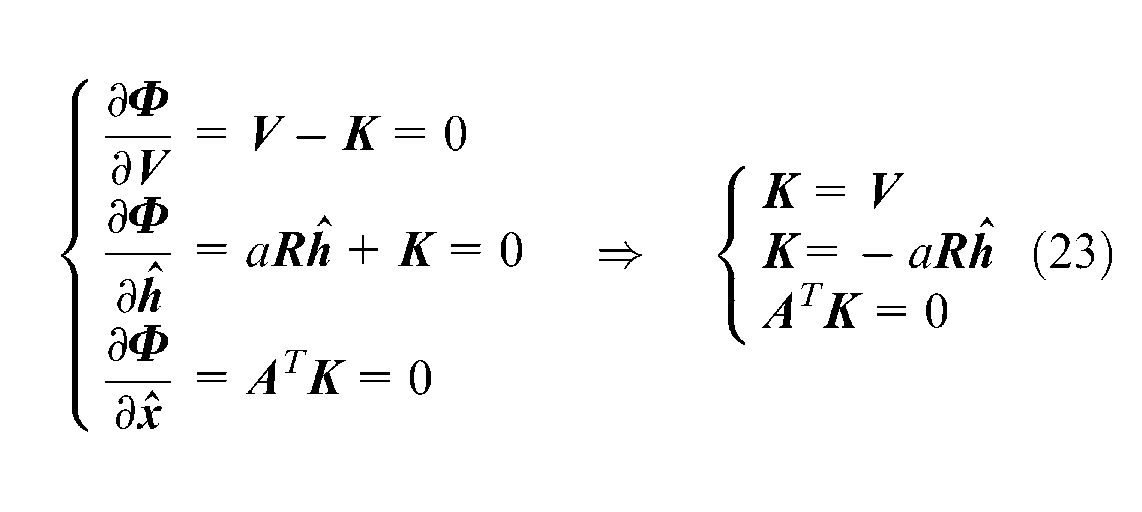
Denoted by
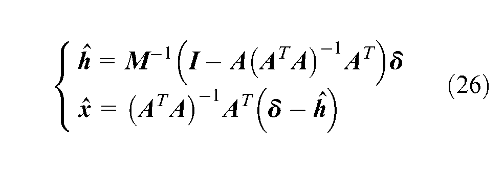
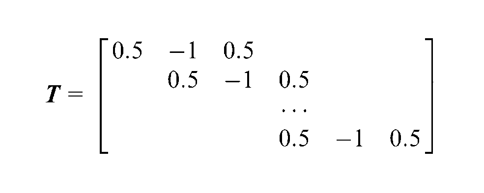
In practice, the regular matrix
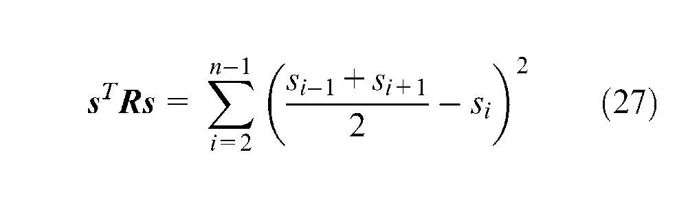
where the differences between si and

where
Similarly, the smoothing factor a, which is used to balance the smoothness against fidelity to the observed points, can be selected according to the minimizer of the generalized cross-validation (GCV) criterion. That is
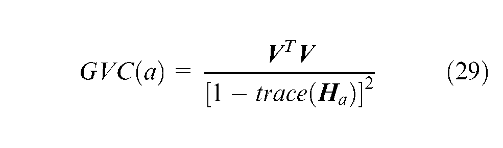
where trace(
Experiments
This section conducts experimental comparisons between the proposed SPRM and the conventional PM.
Experimental setup
As shown in Figure 8(a) and (b), the schematic of the experimental setup includes a two-degree-of-freedom miniature ISP, a turntable system, and a data acquisition and processing system.
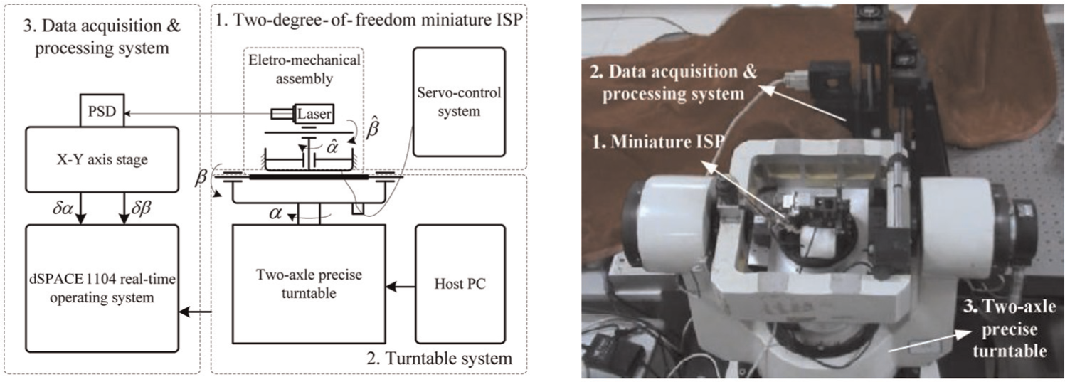
Experimental setup: (a) schematic and (b) test apparatus.
The miniature ISP is shown in Figure 9. It works at stabilization, pointing or tracking mode according to the commands of host PC. And it was designed with an angle movement range from −70° to 70° in azimuth and from −50° to 20° in elevation and an angle resolution of 40.5″ that was determined by an encoder with 32,000 signal periods/resolution; the laser range finder was artificially placed diagonally up to exaggerate the pointing error for the convenience of test and comparison; the equipment requires calibration. The turntable system includes the host PC and a two-axle precise turntable with an angle movement range of ±360° in azimuth and elevation and an angle resolution of 25.92″ that was determined by encoder with 50,000 signal periods/resolution, which is used to provide the reference signal of the pointing direction for the ISP. The data acquisition and processing system includes a two-dimensional (2D) position-sensitive detector (PSD), x–y axis stage, and dSPACE 1104 real-time operating system. This system provides the experimental measurements of pointing errors.
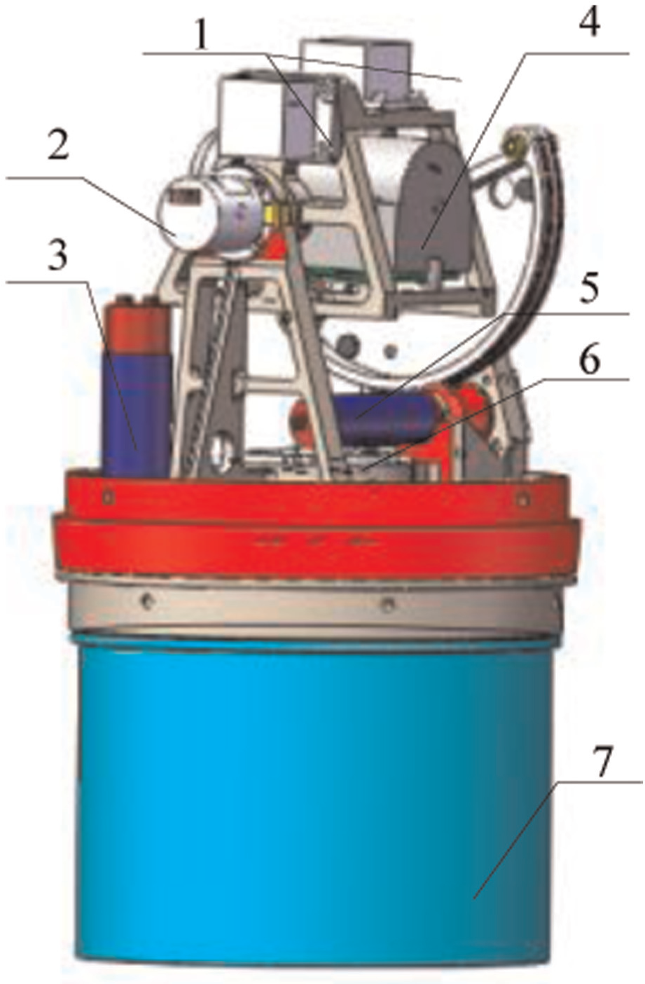
Configuration of a miniature ISP (1: gyroscope; 2: elevation encoder; 3: azimuth motor; 4: visible spectrum camera; 5: elevation motor; 6: azimuth motor; 7: the servo-control system).
The procedure that is used to evaluate the performance of the improved SPRM and the conventional PM is listed as follows:
Preparation for calibration is undertaken. First, the miniature ISP is mounted at the center of the inner gimbal of the two-axle precise turntable. The PSD is then placed on the x–y axis stage that is mounted on a passive optical table. Third, the axes of ISP, PSD, and turntable are mounted at a coaxial alignment. Meanwhile, the laser LOS of ISP is adjusted to point at the center of PSD through the movement of the x–y axis stage, and the scale of the pointing angle and PSD output is precisely calibrated and determined as 0.2°/V. Finally, the equipment is restarted, the ISP works at pointing mode.
The pointing errors are acquired. As shown in Figure 8(a), the indicated pointing angles of ISP are the negatives of the actual pointing angles of turntable (i.e.
Step 2 is repeated. The pointing angles of ISP and turntable are changed to different directions within the movement range, and all of the pointing angles and errors are recorded using dSPACE 1104 real-time operating system.
Data processing of the pointing errors is performed. As shown in Figure 10, the pointing angles and errors are utilized to identify the PM parameters, and residual nonlinear errors remain after compensation. If the residual errors do not have the characteristics of white noise, offline SPRM is employed to compensate further for the pointing errors. Finally, the residual errors of the SPRM and PM are analyzed and compared to select the appropriate ISP model.
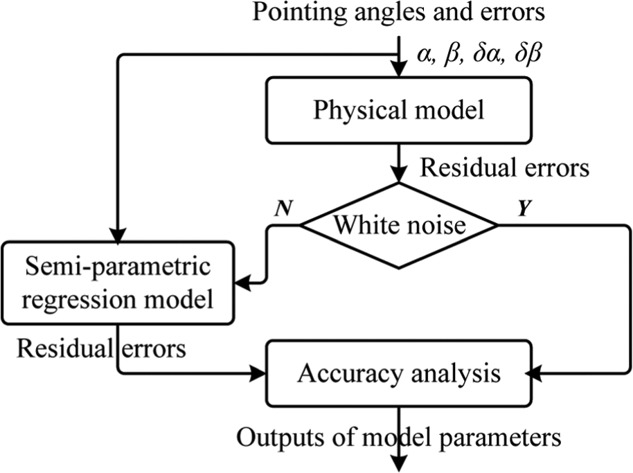
Data processing of pointing errors.
Comparisons of pointing accuracy
The performance of the improved SPRM and the conventional PM was evaluated by following the testing procedure that was described in the previous section. As a baseline for these evaluations, measurements of the pointing angles and errors are obtained, as shown in Figure 11.
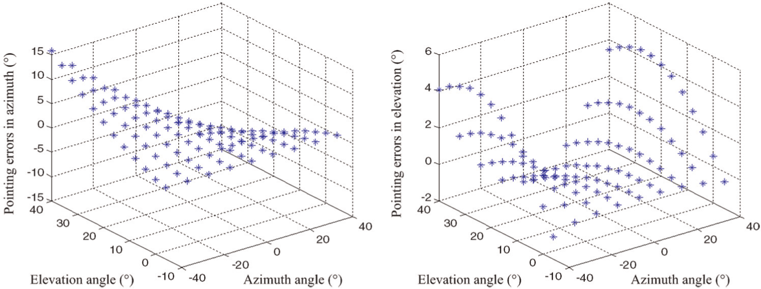
Measurements of pointing errors: (a) in the azimuth and (b) in elevation.
Due to the effects of the geometric and nonlinear errors, the miniature ISP has poor pointing accuracy, as indicated by the errors of −15° to 15° in azimuth and −2° to 6° in elevation. The error value is mostly contributed from artificial misassembly.
The PM is then utilized to fit the measured points of pointing errors, as shown in Figure 12(a) and (b). The labels “Raw” and “PM” represent the measured points and fitting surface of the PM in Figure 12(a) and (b), respectively.
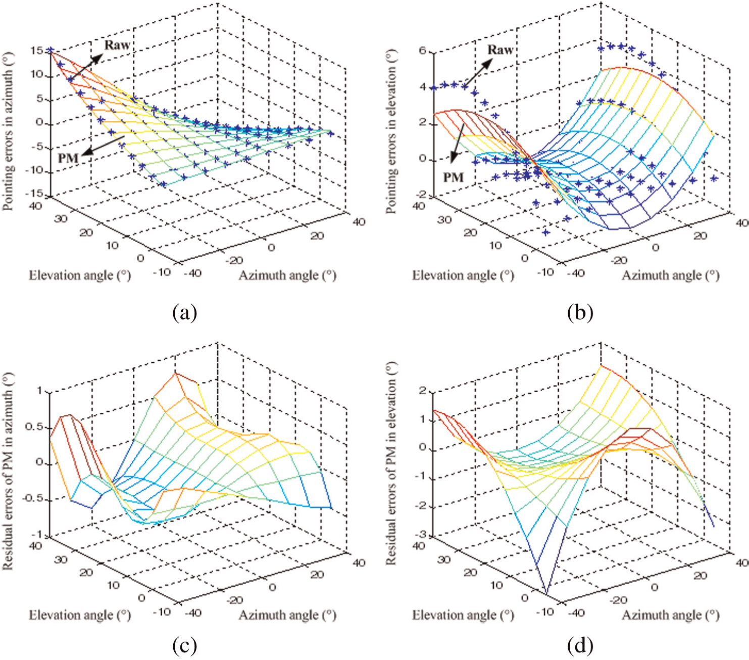
Fitting surface and residual errors of the PM: (a, b) PM fitting surface of pointing errors in the azimuth and in elevation, respectively and (c, d) PM residual errors after compensation in the azimuth and in elevation, respectively.
For comparison, Figure 12(c) and (d) presents the remaining residual errors after compensation using the PM. This comparison shows that the PM effectively compensates for the effects of the geometric errors and improves the pointing accuracy of the miniature ISP, as shown by the errors of −1° to 1° in azimuth and −3° to 2° in elevation. On the other hand, these remaining residual errors are not white noises due to the effects of the nonlinear errors, which are not considered in the PM. Therefore, by following the testing procedure, an improved SPRM is employed to process the measurements of pointing errors to compensate for nonlinear effects.
As shown in Figure 13(a) and (b), SPRM is utilized to fit the measured points of pointing errors. The labels “Raw” and “SPRM” represent the measured points and fitting surface of SPRM in Figure 13(a) and (b), respectively. The results indicate that the SPRM surface fits well compared with that of the PM.
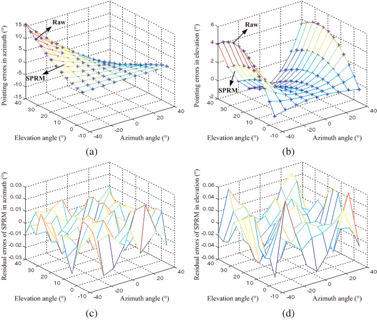
Fitting surface and residual errors of SPRM: (a, b) SPRM fitting surface of pointing errors in the azimuth and in elevation, respectively and (c, d) SPRM residual errors after compensation in the azimuth and in elevation, respectively.
For comparison, the remaining residual errors after compensation using SPRM is also presented in Figure 13(c) and (d), which ensure that SPRM is shown to substantially outperform the PM, and the pointing accuracy of the miniature ISP has been significantly improved, as shown by the errors of −0.03° to 0.03° in azimuth and −0.06° to 0.06° in elevation. Moreover, the remaining residual errors of SPRM are evaluated according to the guidelines given in the study of Eubank. 28 These errors are determined to be white noise due to the fact that the geometric and nonlinear errors are compensated by the proposed method.
Additionally, compensation for the pointing errors using the proposed SPRM and the conventional PM was achieved using computer software, which calculate the compensation values at each pointing angles and made the data available to the ISP’s control system. Table 1 lists the pointing accuracy before and after error compensation, along with a series of randomly selected pointing angles. The sum of squares δ is defined as
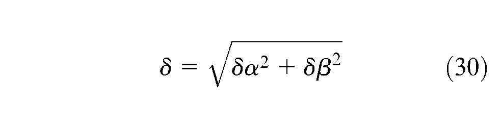
where δα and δβ are the pointing errors in azimuth and elevation, respectively.
Pointing accuracy before and after error compensation.
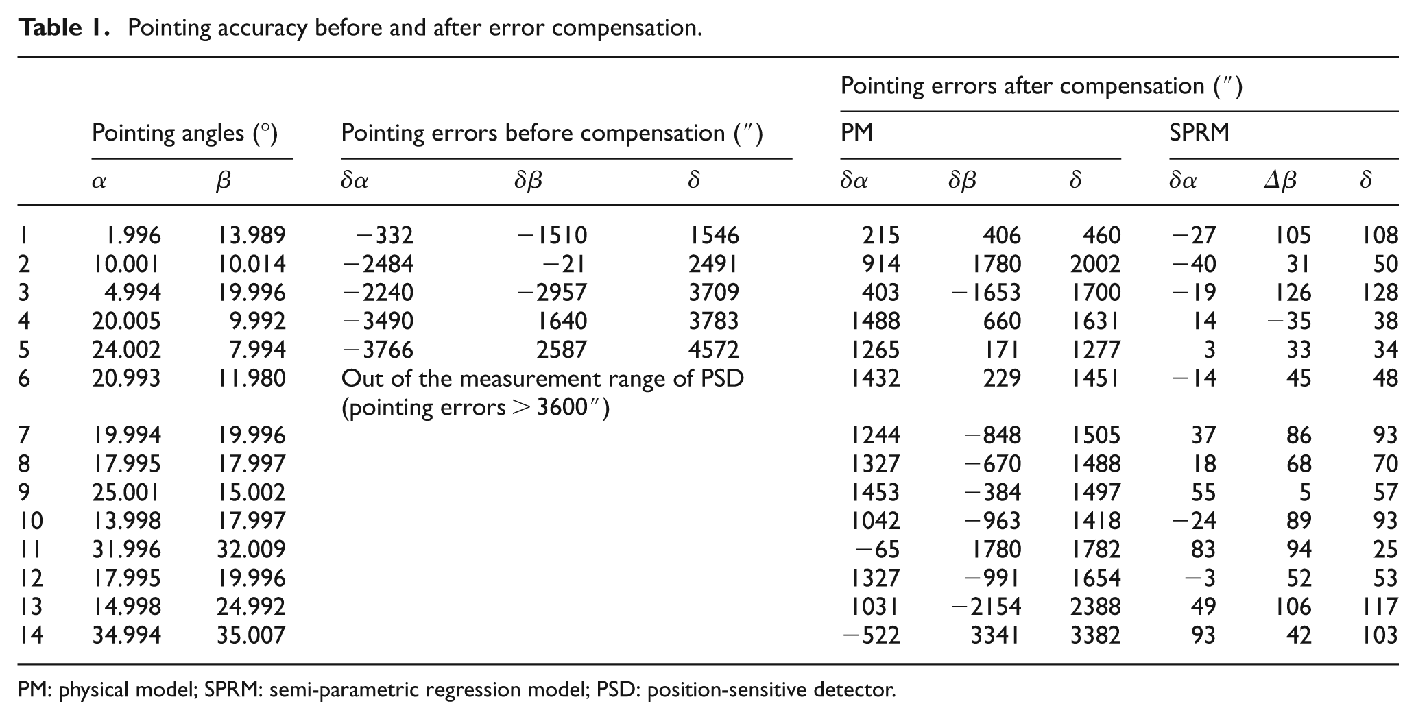
PM: physical model; SPRM: semi-parametric regression model; PSD: position-sensitive detector.
As shown in Table 1, the pointing accuracy after compensation improved significantly. Moreover, the proposed SPRM provides higher accuracy than does the conventional PM.
Conclusion
In this article, offline modeling and online calibration issues are investigated from both theoretical and experimental aspects to improve the pointing accuracy of ISP. The following conclusions can be drawn:
A PM that was based on the comprehensive analysis of error sources and kinematic modeling with the D-H notation was established to illustrate the effects of geometric errors on the pointing accuracy of ISPs.
A improved hybrid model, which is called the SPRM, was developed to compensate for the remaining nonlinear errors.
A testing procedure for error compensation was achieved using the proposed method in a two-degree-of-freedom miniature ISP. The pointing accuracy of the miniature ISP has been significantly improved, as shown by the errors of −0.03° to 0.03° in azimuth and −0.06° to 0.06° in elevation, which is better than that of −1° to 1° in azimuth and −3° to 2° in elevation with the PM compensation, and better than that of −15° to 15° in azimuth and −2° to 6° in elevation before error compensation.
The remaining residual errors of SPRM are determined to be white noise.
Footnotes
Funding
This study was supported by the National Natural Science Foundation of China (grant number 51105372).