
Abstract
In this paper, the machinability of a fabricated AM alloy (Mg-7 wt%Al-0.9 wt%Mn) has been examined. The novel AM alloy was subjected to turning using a systemized CNC setup. The input turning variables: feed (f), cutting speed (v), and depth of cut (DOC) were suitably altered to analyze effects on response variables such as cutting force (Fc), cutting temperature (T), and tool life (TL). Subsequently, the microstructure characterization of the machined surface was done for validating the experimental results. The experimental results established the influence of input parameters on response variables. The cutting force was mostly dominated by DOC, and the cutting temperature was predominantly influenced by cutting speed. The SEM images exhibited the adverse effect of higher values of input parameters on the surface condition. The finest surface was observed at f: 0.1 mm/rev, DOC: 0.5 mm, and v: 115 m/min. Further, the analysis of tool life was done by assessing the flank wear; the measured data showed the significant influence of cutting speed on flank wear. The maximum tool life of 51 min was achieved at the lowest levels of three input parameters.
Introduction
Magnesium has a specific density of 1.74 g/cm3, making it lightest among all structural metals; its density is 35% and 78% less than aluminum and steel. 1 Mg alloys are preferred due to their favorable inherent properties like density, stiffness, castability, and thermal conductivity. 2 ASTM B951-11(2018) standard describes the Mg alloys’ coding system and also enunciates the popular Mg alloys’ series like AM (Al-Mn), AZ (Al-Zn), ZC (Zn-Cu), AS (Al-Si), AJ (Al-Sr). AM series (AM20, AM50, and AM60) Mg alloys are significantly consumed in industrial applications owing to their good tensile and corrosive properties. Luo 3 discussed several parts made using AM50 and AM60 alloys; these include vehicle seat stands, navigation wheels, gadget boards, supports, crosspieces, electronic gadgets, etc.
During the choice of materials and alloys for different applications, ease of machining is an important deciding factor. The main purpose of machining is to remove the undesired material to get a part of the desired specification and surface integrity. 4 Mg alloys qualify criteria to manufacture different parts, but their machining requires many deliberations due to their low melting point and high inflammability. The flammability aspect of Mg alloys is a major hurdle during machining. Hou et al. 5 reported ignition and sparks in machining AM50A alloy. They found non-optimal machining parameters as the primary reason for ignition and flares in the chips. Housh and Waltrip 6 highlighted the safety considerations during machining of Mg alloy, these include appropriate tools and their angles (rake and relief), dry machining (Due to Mg’s high reactivity with water and related coolants), controlled feed, and restrained speed. Carou et al. 7 highlighted the risk of inflammability associated with Mg alloys machining when the temperature reaches 450°C and beyond; they suggested that cutting temperature (T) during the Mg alloys machining must be observed stringently. Currently, many studies are under progress for developing non-flammable, non-corrosive Mg alloys with promising machinability to attain a surface with a high degree of integrity. 8
In machining, turning is the crucial and favored metal removal operation for the fabrication of diverse parts. 9 Turning has three important input parameters: feed, DOC, and speed; these parameters are appropriately changed to get desired results on response variables. Imani et al. 10 highlighted the researchers’ efforts to get desired effects on the response variables by varying the input parameters; the authors used neural networks and genetic algorithm to optimize output variables. The input parameters of turning, influence cutting force, cutting temperature, and tool wear rate and these three machining characteristics have a strong bearing on surface integrity and properties of machined parts.11–14 Kaining et al. 15 studied the machinability of AZ91D Mg alloy; the achieved results highlighted that cutting force reduces with higher speeds, contrary the cutting force tends to surge with the increasing feeds. Yalcin et al. 16 conducted a study on AISI 1050 steel, their findings revealed that cutting settings and tool properties govern the cutting force, and the variation in force changes the average surface roughness. Lu et al. 17 discussed the influence of turning parameters through the machining of AZ31 alloy; they reported that feed and DOC has a considerable effect on cutting force. Pawade et al. 18 evaluated the high-speed machining of Inconel 718, and revealed that machining variables regulate the cutting temperature, and the temperature influences surface integrity, modifies microstructure, and generates residual stress. Furthermore, the temperature increase becomes critical when materials of low melting points are machined, the chips of such materials during machining may readily get molten and diffuse with the material, resulting in the inferior surface finish. Patil et al. 19 during research on titanium alloy, discussed that using a higher cutting speed to get an enhanced removal rate would increase the temperature, thus undesirably affecting the machinability.
Similarly, past research highlights the effect of machining variables on tool-life.20,21 Tamizharasan et al. 22 examined the effect of turning variables on PCBN cutting-tool inserts; they reported that speed has maximum influence on the tool life, while DOC has a minimal effect. Nur et al. 23 studied the turning parameters impact in machining AISI 316L alloy, their findings exhibited that speed and feed are inversely proportional to the tool life. The above discussions highlight Mg alloy’s superiority for different applications, but its machining entails challenges. Therefore, it becomes extremely crucial to analyze the impact of machining variables in cutting newly fabricated Mg alloys to address the machinability issues. This paper investigates the effect of input parameters on the selected response variables in turning AM alloy to ascertain its machinability. The experiments were conducted by altering feed, cutting speed, and DOC, and the measured values of the response variables, such as cutting force (Fc), cutting temperature (T), and tool life (TL), were tabulated and analyzed.
Materials and methods
Material and its properties
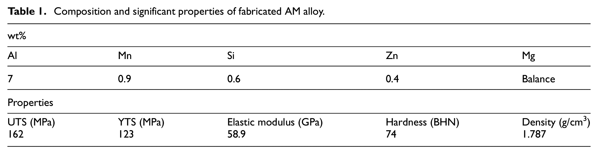
The machinability study was conducted on the fabricated AM series Mg alloy. The composition of novel AM (Aluminum and Manganese) highlighted in Table 1, was decided based on the literature survey, phase diagrams, and characteristics of commercial Mg alloys, however, the alloying criteria were not in the scope of the study therefore, it has not been deliberated. Stir casting was employed for alloy development; it is a popular and economical process of alloy development in the liquid state, involves mixing molten base metal with the powder form of alloying elements by performing stirring action. 24 The stir cast billets had a diameter and length of 36 mm and 200 mm. After the development of alloy, its mechanical properties were measured. The tensile tests were conducted using a Zwick/Roell (Make: Zwick/Roell (Z100) with CAL facility; load cells: 100 kN and 5 kN) tensile testing set-up. Vickers hardness was measured with the help of Mitutoyo, HM-200 testing machine. The properties of the fabricated AM alloy are highlighted in Table 1.
Composition and significant properties of fabricated AM alloy.
Cutting conditions
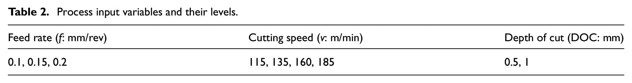
The alloy development and mechanical characterization were followed by a turning operation on cylindrical billets. The experiments were done on a CNC lathe HMT-PRAGA (Model: PTC-200) with a monolithic cast iron single-piece bed base structure inclined 30° to vertical, having positional accuracy: ±0.003 mm (X-axis) and ±0.004 mm (Z-axis), with swing over bed = 460 mm, spindle speed 100–4000 rpm, feed rates 1–5000 mm/min, and FANUC 0i-Mate control system for parameters selection. The maximum possible turning length and diameter on the CNC was 600 mm and 250 mm. An uncoated square carbide insert (composition: a hard, low binder content, unalloyed WC/Co fine-grain grade) with tool geometry: clearance angle major 0°, included angle 90°, corner chamfer angle 90°, rake angle +5° was used for turning. The square inserts were replaced with new ones after the inserts had been worn out during the course of cutting. For turning, orthogonal cutting was employed. During the experimentation, the cutting speed (four selected values) and feed (three selected values) were changed first, and the third variable DOC was kept constant. Subsequently, the feed rate was kept constant, and the DOC (two selected values) was varied. The nose radius was 0.4 mm for all cutting combinations to distinctly identify three turning parameters’ influence. The selection of different turning parameters’ levels was based on the CNC capability and sensitivity of Mg alloys against high temperatures. The process variables and their levels are given in Table 2.
Process input variables and their levels.
Measuring hardware
CNC lathe was systemized by employing external hardware to facilitate consistent measurements of response variables. Kistler’s dynamometer for measuring the cutting force (Fc) was integrated with the CNC lathe. An A/D converter was used to convert force analog signal to a digital signal; for the conversion, a Kistler 5073 multi-channel charge amplifier (repeatability <±0.05) was used. Subsequently, the converted signal was conditioned by a signal conditioner and fed to the computer. The CFM software installed in the system displayed the cutting force. The cutting temperature was measured with the help of thermal imaging (TI) digital camera FLIR-E60 (Sensitivity: 0.05°C) with a 20°C to 650°C range. The camera was positioned near the CNC lathe for the precise focus of IR rays. Besides, dry cutting enabled the convenient aiming of IR rays in the cutting zone. The graphic representation of the setup used for experiments is shown in Figure 1(a).
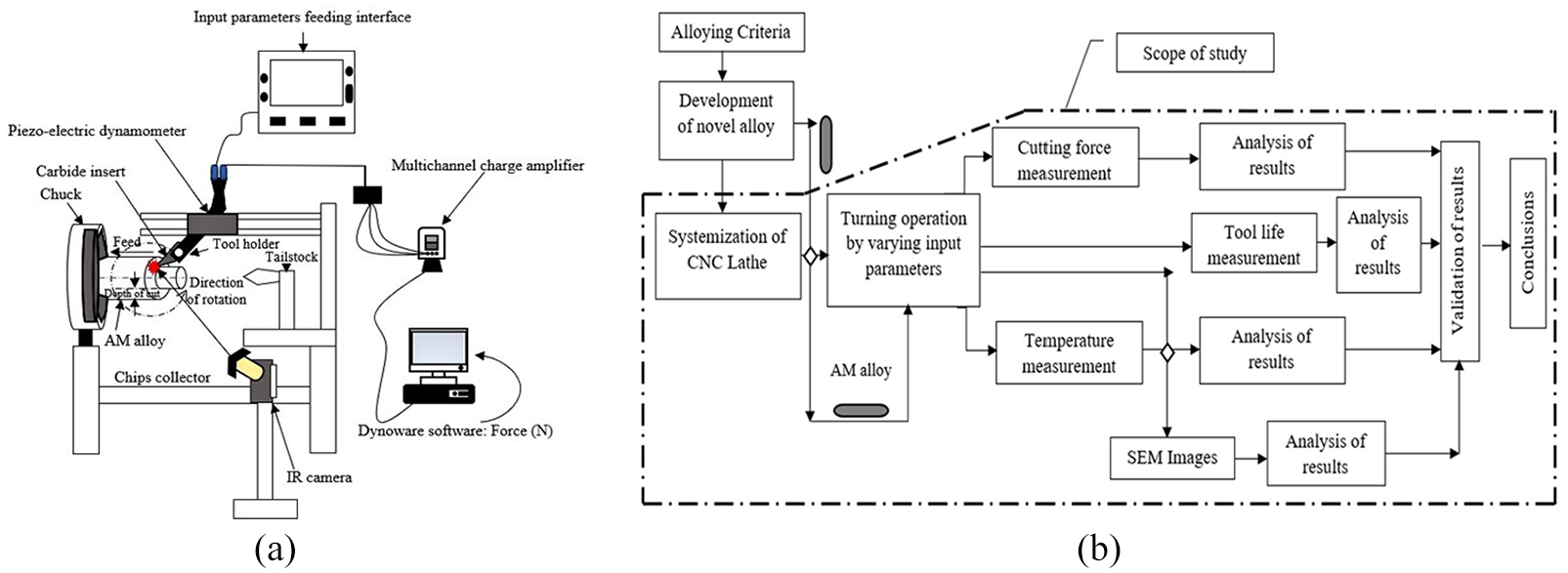
(a) Schematic of CNC lathe along with attached hardware and (b) the flow chart of the study.
The tool life based upon the flank wear measurement was noted for different combinations of feeds, DOC, and speeds. An optical microscope (Olympus STM 6) with four fine focusing speeds: 800/400/200/50 µm in four steps, illumination 12 V, measuring accuracy: 50 mm stroke: (3 + L/50) µm was used for the flank wear measurement.
For surface topography analysis at the microstructural level, a FE-SEM (Field Emission-Scanning Electron Microscopy; Make: FEI, Model: Apreo LoVac) with a high resolution 1.5–2 nm was used. The setup can be favorably used for acquiring topographical morphology and elemental findings at magnifications of 10×–3 × 10⁵× with practically unrestricted and unlimited depth of field. SEM features are also conducive for imaging non-conducting samples, when imaging is done using inverse bias mode. For SEM images, the specimens were reduced to a cylindrical section (r = 3 mm and ht = 5 mm) using wire-cut Electro discharge machining (EDM). Subsequently, the specimens are placed into an evacuated chamber for images post interaction with electron beams. The SEM images were examined to understand the effect of cutting force and temperature at different combinations of input parameters. Figure 1(b) shows the flow chart of the study. The area inside the dotted line shows the study’s scope, and the same is deliberated in the paper.
Results and discussion
Effect of turning variables on cutting force
The cutting force (Fc) in turning AM (Mg-7 wt%Al-0.9 wt%Mn) alloy was examined by varying input parameters. For analyzing the influence of feed, the DOC was maintained at 0.5 mm, and the nose radius was fixed at 0.4 mm. The cutting length (40 mm) was uniform for all measurements. The feed was varied to three different levels (f (mm/rev): 0.1, 0.15, 0.2). The speeds for each of these feeds were changed to four different levels (v (m/min): 115, 135, 160, 185). Figure 2(a) illustrates the joint effect of feed and speed on the force. The plotted data show that cutting force rises by 46.15%, 37.28%, 43.10%, and 45% respectively at four selected speeds when the feed rate increases from 0.1 to 0.2 mm/rev. This can be assigned to the fact that with the rise in a feed rate, additional resistance is offered by the material in the tool path due to the high rate of shearing, which results in enhanced values of cutting force. Further, the rise in feed leads to enhanced MRR, which increases substantial pressure on the tooltip due to increased volume of material being removed, leading to higher cutting force, and the coefficient of friction is proportional to cutting force, thus the friction rises significantly. 25 Besides, the dry cutting conditions lead to additional resistance in the form of friction. Additionally, with the increase in feed, the force increases because of the enhanced chip load; the Chip load = feed × approach angle factor (the angle formed between the side cutting edge and a plane vertical to the direction of feed is called approach angle). Many past studies have defined the empirical relationship between force and cutting parameters. 26 The popular Kienzle-Victor model explains the relationship between cutting force, feed, and DOC; the equation (1) below highlights this relationship. 27
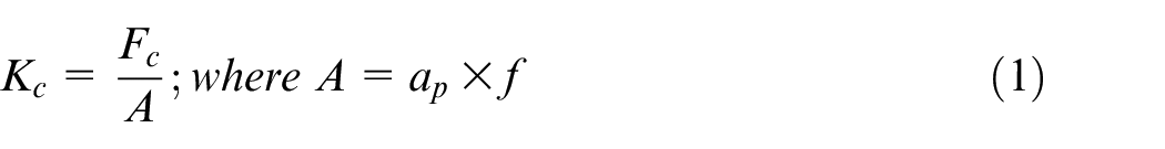
where Kc: specific cutting force; Fc: main cutting force; A: chip cross-section; ap: DOC; f: feed. Further, the higher cutting force resulting from increased feeds leads to an inferior surface quality having feed marks, surface burning, and cracks. Many past studies have reported a detrimental effect of the higher feeds on surface roughness.11,12 The expression defining the relationship between the feed rate and surface roughness is given below. 28

where Ra: average surface roughness (µm); f: feed rate; r: nose radius. From equations (1) to (2), it can be concluded that Fc (N) has a significant influence on Ra (µm). The SEM images discussed in sub-section 3.4 supports the adverse effect of higher feed rates on surface quality.
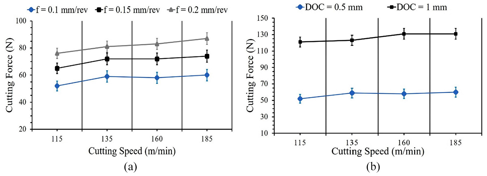
Effect of machining variables: (a) Fc versus speed and feed and (b) Fc versus DOC.
With a rise in cutting speed from 115 to 185 m/min for three different feeds, the corresponding rise in Fc (N) was 15.38%, 13.84%, and 14.47%. Figure 2(a) exhibits cutting force rise at a rapid rate till 135 m/min; after that, the increase is gradual. At enhanced speeds (160 and 185 m/min), the effective time for dissipation of heat becomes scarce, causing a temperature rise, and this brings the thermal softening, which makes easy material removal at reduced cutting force. Correspondingly, it may be partially due to a rise in shear-plane angle with a surge in speeds (higher cutting speed tends to reduce chip thickness leading to higher chip thickness ratio), which decreases the chip-tool interaction area, leading to increased shearing, and thus contributing to cutting force reduction. 29 Besides, the cutting force reduction leads to a decline in friction force, which causes the coefficient of friction to descent.
Figure 2(b) shows the effect of DOC on Fc (N) at fixed f: 0.15 mm/rev; it was observed that the cutting force rises with DOC. The Fc (N) rises significantly by 133%, 108%, 125%, and 118%, at four cutting speeds with an increase in DOC from 0.5 to 1 mm. This is because a high DOC leads to the formation of thick and snarled chips, which increases the friction due to rubbing action in the rake face, causing hindrance in the smooth flow of chips, and thus results in higher forces.
Further, the increase in DOC tends to intensify the abrasion between tool-workpiece, thus contributing to a rise in the cutting force. Besides, the increased DOC results in the enhanced interaction area of the tool-workpiece, which causes a surge in the cutting force due to a rise in uncut chip cross-section; equation (1) above corroborates this particular effect of DOC. The discussions distinctly highlight that the most favorable means to control the Fc (N) is to change the DOC and feed. If the cutting conditions cannot be changed for some reason, it should preferably be controlled by changing the tool’s rake angle. 30 Furthermore, the detrimental effect on surface roughness (cracks, voids, and indentation) at higher DOC was examined with microstructural images (Sec 3.4).
Effect of turning variables on cutting temperature
Figure 3(a) reveals the influence of input variables on the temperature. The data illustrate the temperature rise with feed rate. The temperature rises by 10.98%, 10.71%, 14.64%, and 19.08% at four different speeds, with the feed rate rise from 0.1 to 0.2 mm/rev. This was essentially due to the length traversed by the tool per revolution becoming more with increased feeds, which causes higher friction between the tool and workpiece, leading to higher temperatures. Further, the chips’ cross-section increases with feed, generating more heat in the shearing zone, leading to cutting temperature rise. It was also seen that with an ascent in speed at different feeds, the cutting temperature increases significantly; the % increase in the temperature at three different feeds is 20%, 32%, and 29% for a rise in speed from 115 to 185 m/min. The temperatures measured with an infrared camera at 0.1 mm/rev are shown in Figure 3(c) to (f); a jump in temperature from 54.6°C to 65.1°C was observed for a speed increase from 115 to 185 m/min. Similar trends for temperature were captured for other combinations of feed and speed. The maximum temperature of 78°C was observed at 0.2 mm/rev and 185 m/min during the AM alloy machining. The increasing speed continuously changes the chip shape from minuscule grain-sized to continuous snarled ribbon chips. The ribbon-type chips obtained at high cutting speed tend to hinder the smooth movement of chips out of the cutting zone, which adversely affects conduction, leading to temperature rise. 31 The temperature has a strong dependence on cutting speed; the notation below testifies this relationship. The equation explains that temperature rise is directly proportional to the square root of cutting speed. 32

where Θ ov : overall temperature; Uc: specific energy; v: cutting speed (m/min); t1: uncut chip thickness (mm); k, ρ, and c: are thermal conductivity, density, and specific heat of the material.
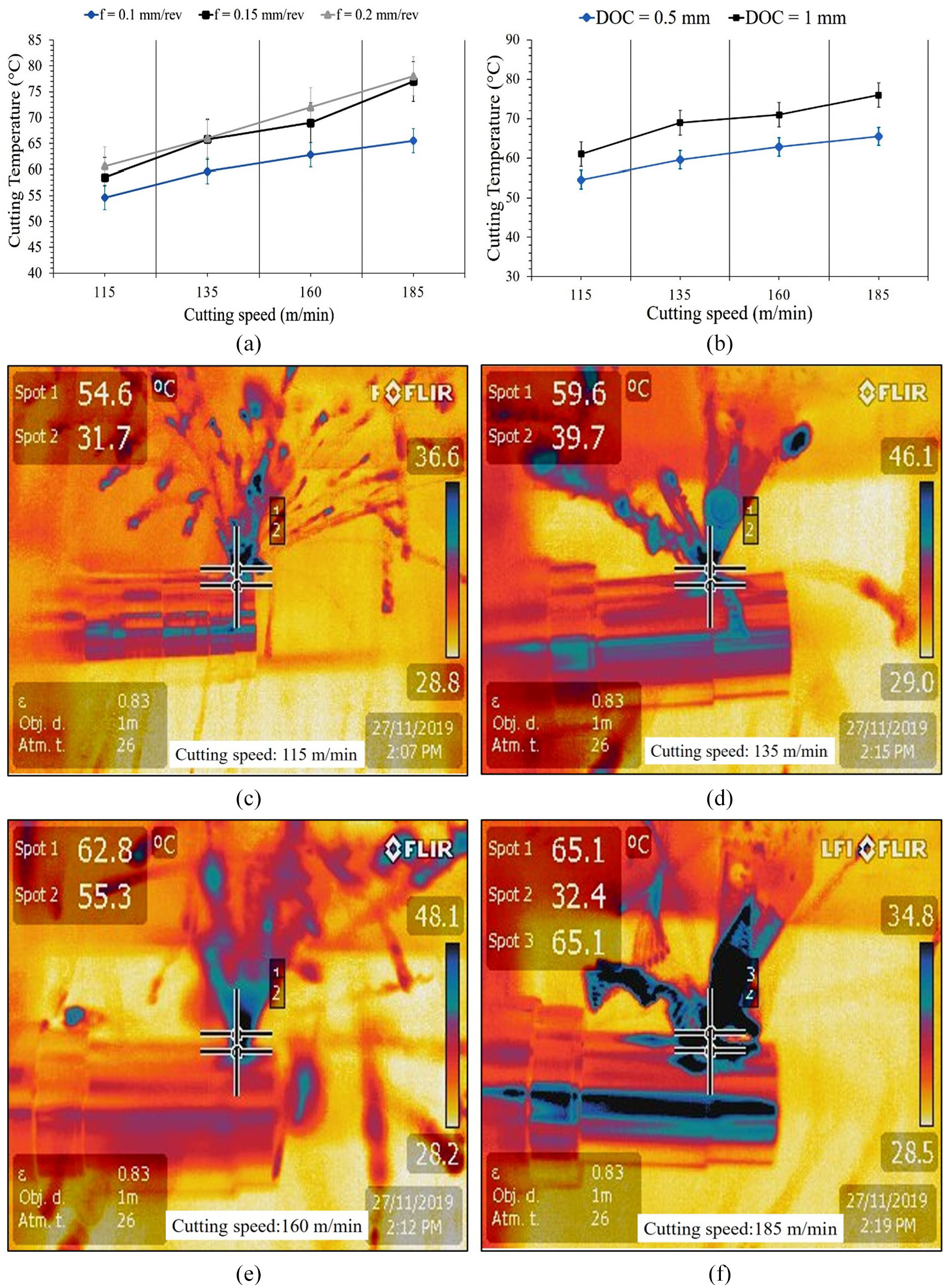
Effect of machining variables: (a) cutting temperature versus feed and speed, (b) cutting temperature versus DOC, (c) temperature at 115 m/min, (d) temperature at 135 m/min, (e) temperature at 160 m/min, and (f) temperature at 185 m/min.
As explained above, the higher speed leads to a reduction in Fc (N), which is favorable for the surface quality; however, at higher speeds, the temperature at the contact point (tool-workpiece) tends to go beyond the thermal range of the tool material, harming the tool edge, and adversely affecting the surface quality. Thus, an appropriate selection of cutting speed is very crucial. Also, Mg alloys’ susceptibility to fire is critical, needing adequate deliberation before the experiments.
Figure 3(b) highlights the temperature rise with DOC. The temperature rises by 11.72%, 15.77%, 13.05%, and 16.03% respectively for a rise in DOC from 0.5 to 1 mm at constant feed of 0.1 mm/rev. An increase in DOC increases the work done in removing excess material from the workpiece, which causes additional transfer of energy in the form of heat to chips, and this enhanced heat energy causes temperature rise. Additionally, at high DOC, the interaction time between chip and rake surface increases before getting scattered into the air, raising the temperature. The relationship between the temperature, DOC, and feed was proposed by Kronenberg with the help of an equation given below. 33

where C0 and C1: constants; vc: cutting speed; A: cross sectional area of uncut chip. As explained above the chip cross section area

Equation (5) verifies the dependence of temperature on three turning parameters. From the above graphs and equation (5), it is evident that the influence of feed and DOC on cutting temperature is comparatively smaller than that of cutting speed. This is principally due to the large part of the heat generated in cutting being taken away by the produced chips, and thus the temperature is hugely swayed by the cutting speed. 30
Tool life analysis
Estimation of tool performance is one of the most important criteria to assess machinability. The tool life is significantly influenced by the machining variables and hardness of the workpiece material. 22 ISO 3685 (1993) standard brings out the tool-wear measurement criteria, and it highlights the assessment of flank wear for determining the tool-life. Flank wear occurs on the cutting tool due to the rubbing motion between the tool and the workpiece. Figure 4 shows the location of the flank wear. Tool-life (TL) is typically evaluated by the total machining time in minutes for which a particular tool is used before its flank is worn out. The ISO 3685 (1993) specifies the limits of flank wear; a turning tool should have less than 0.76 mm flank wear during roughing and 0.38 mm during finishing. 34 The extent of flank wear (Vb) can be measured as the distance between the top of the cutting edge and the bottom area where flank wear occurs. 35 The flank wear was measured using an optical microscope. It was observed in turning AM alloy that flank wear was the prime cause of carbide inserts’ failure.
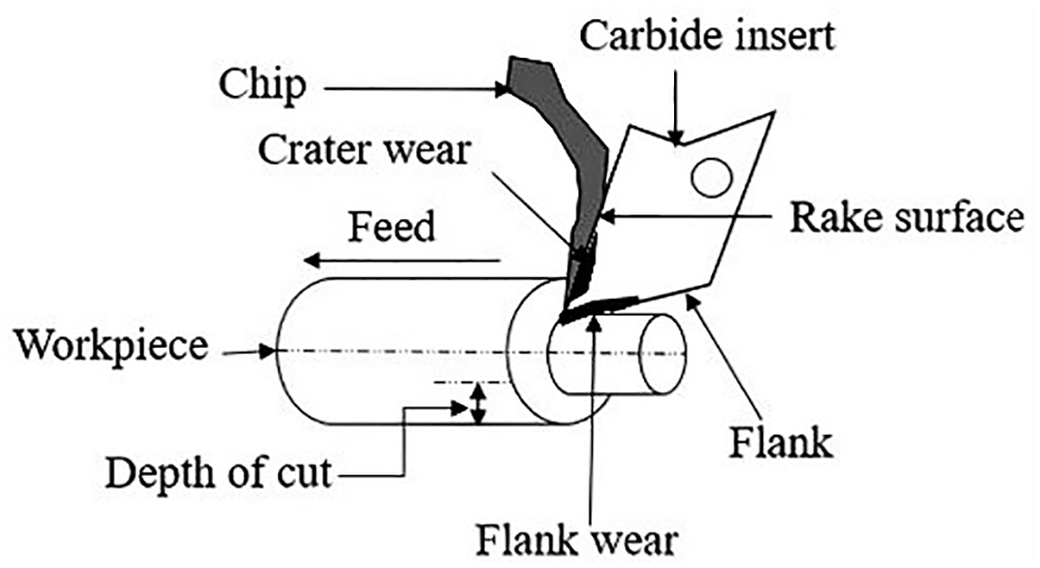
Schematic of tool flank wear.
The SEM analysis of the worn-out carbide inserts was carried out to validate the results. Figure 5(a) to (d) shows the SEM images of flank wear at different magnifications.
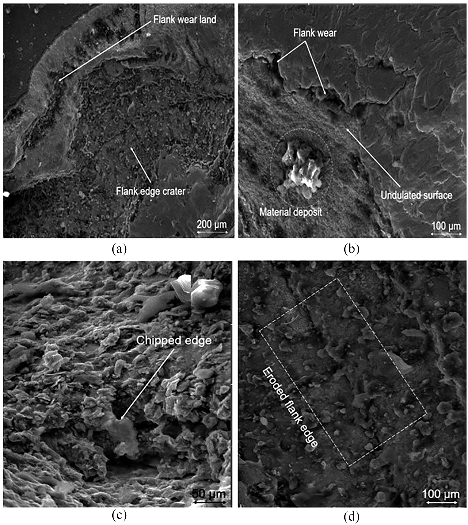
Tool condition post-machining: (a) Flank wear land, (b) Flank wear and undulated surface, (c) Chipped edge along the flank surface, and (d) Eroded flank edge.
For evaluating tool life, the cutting parameters were appropriately altered; the experiment results were tabulated and plotted. Figure 6(a) highlights the tool life (TL) in minutes; with increasing feed rate at constant DOC (0.5 mm), the tool life decreases. Similarly, a continuous drop with increasing speed for two selected feeds was observed. At high feeds, the material’s adhesion to the tool-face negatively impacts its hardness, which causes reduced tool life. The tool life decreases by 23.52% (0.1 mm/rev) and 37.5% (0.2 mm/rev) when speed rises from 115 to 185 m/min. The tool life at the same speed for a rise in the feed from 0.1 to 0.2 mm/rev reduces between 13% and 19%. The maximum tool life of 51 min was observed at f = 0.1 mm/rev and v = 115 m/min. Figure 6(b) displays the change in tool life with DOC at fixed feed (0.1 mm/rev). With the rise in DOC, the tool life decreases, correspondingly a continuous drop with increasing speed for both the selected DOC is observed. The tool life decreases by 31% (DOC: 0.5 mm) and 33% (DOC: 1 mm) with the speed increment from 115 to 185 m/min. The tool life at the same speed for a rise in DOC from 0.5 to 1 mm reduces between 13% and 15%.
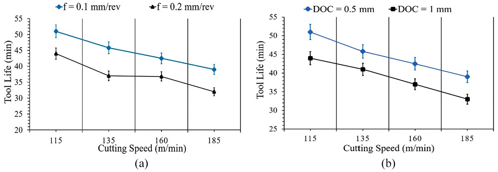
Tool life: (a) TL (min) versus feed and speed and (b) TL (min) versus DOC.
The results reveal that speed is the most crucial factor which has a consistent detrimental effect on the tool life. The increased tool wear witnessed at higher speeds can be attributed to the abrasion produced at the tool’s rake surface during machining. With speed rising from 115 to 185 m/min, the rubbing motion between the carbide tool and AM alloy became intense, causing increased heat production despite less contact time. This generation of excess heat at the flank site made the edge soft, leading to swift flank wear. Additionally, at low speeds, some work material gets fused to the tool’s surface, commonly referred to as Built-up Edge (BUE). The BUE provides a protective layer over the tool’s surface, which improves its strength; but, the BUE is fragile, and it often gets collapsed and separated from the tool surface as the temperature rises at higher speeds. The BUE, while getting detached from the tool body, dislodges some tool material. The chipping off the tool material due to frequent dislodging of BUE unfavorably affects the tool geometry; this leads to early tool failure and unsatisfactory surface finish of the machined part. However, the effect of feed and DOC on flank wear was somewhat low, this was essentially due to their lesser influence on temperature compared to speed (refer equation (5) above). The findings are also supported by the tool life equations of Taylor (equation (6)) and Gorczyca (equation (7)). 36
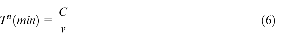
T is the tool-life, and v is the speed; C and n are the constants.
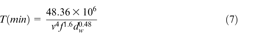
where v, f, and dw are the speed, feed, and DOC. In equation (7), cutting speed (v) has an exponent of four, indicating its substantial effect on the tool-life. Also, the tool wear analysis results are in good agreement with the findings of the past studies. 22
Microstructures of machined surface
Figure 7(a) to (f) shows the SEM images of turned AM alloy at different magnifications. Figure 7(a) and (b) displays the surface conditions at 1 mm DOC. The micrograph shows voids, cracks, and indentation. The obtained images support the experimental results. Figure 7(c) to (f) shows fractured surface, dimples, internal cracks, metal debris, feed marks, scars, and burrs at 0.2 mm/rev. The SEM images strengthen the graph plots and discussions. As stated above, a feed of 0.2 mm/rev resulted in high MRR along with enhanced chip load, which was accompanied by high heat generation, and it led to a surge in cutting force; this resulted in the inferior surface finish with flaws. Several past researchers have reported the severe effect of feed on surface roughness.13,14,25
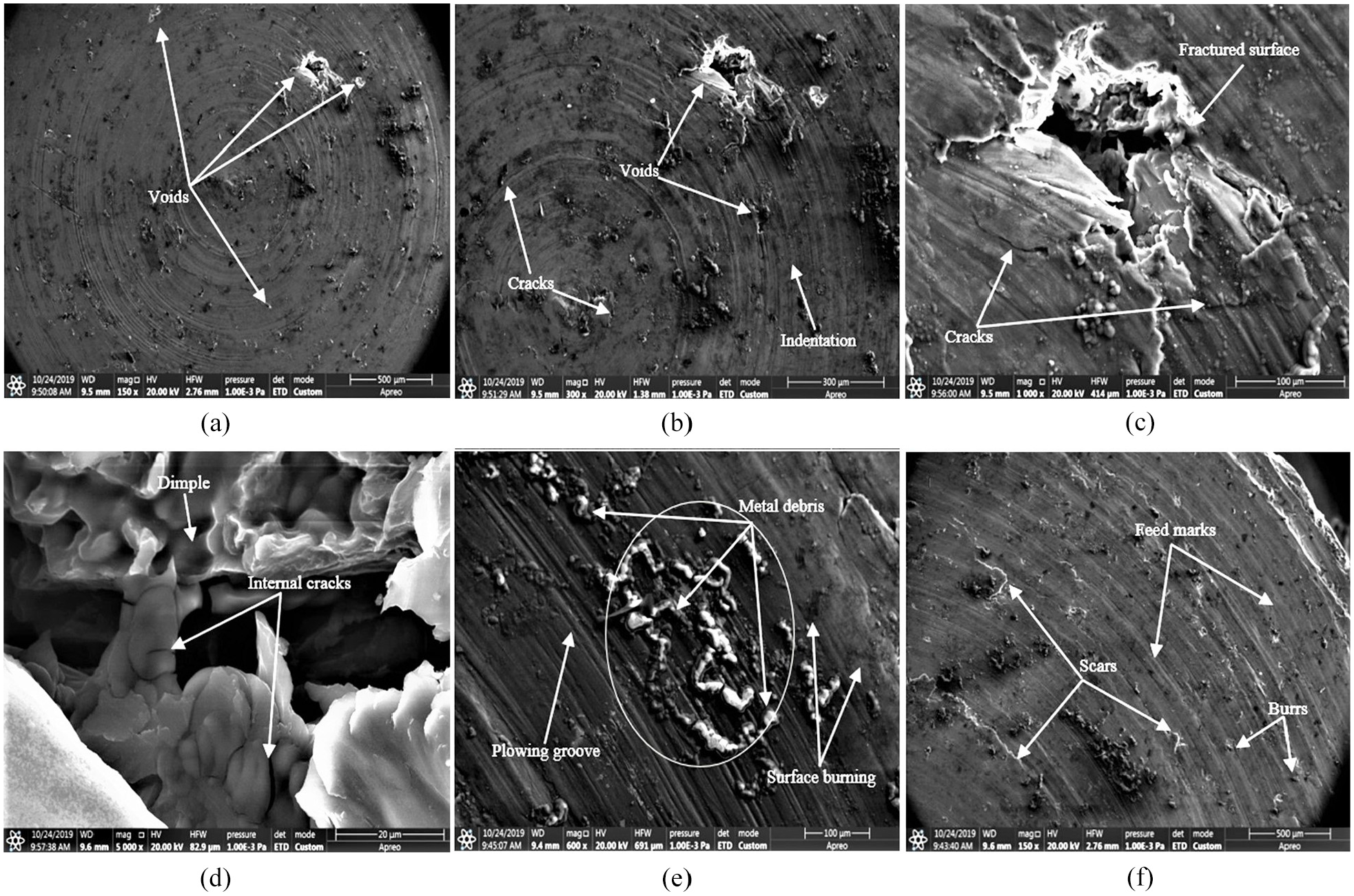
Effect of DOC and feed: (a) voids at 1 mm DOC, (b) cracks and indentation at 1 mm DOC, (c) fractured surface and cracks, (d) internal cracks at high feed rates, (e) surface burnings and metal debris at 0.2 mm/rev, and (f) feed marks and scars at 0.2 mm/rev.
Figure 8(a) shows the surface condition at 185 m/min. The micrograph analysis reveals that high cutting speeds result in the initiation of flaws like metal debris, surface burning, tearing, and smear; however, their occurrence on the surface was somewhat moderate. This is on account of the excess heat produced at higher cutting speeds (185 m/min), which leads to easy material removal, but causes surface burning and tearing. Figure 8(b) shows a finer surface obtained at v: 115 m/min and f: 0.1 mm/rev, however, some random feed marks, surface burning, and microporosity were also detected. The findings were in line with the past investigates.5,37
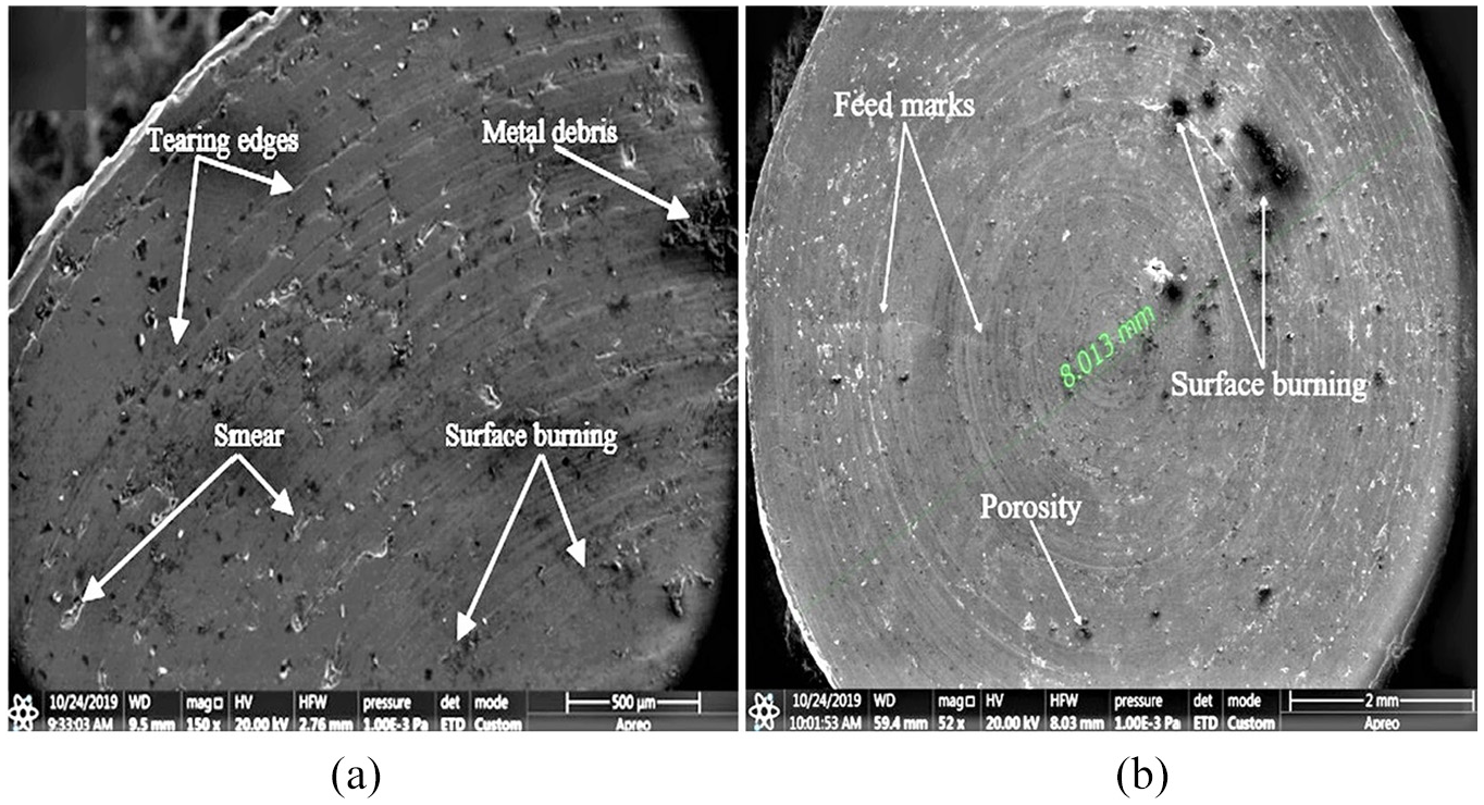
Effect of cutting speed: (a) metal debris, tearing, and smear at 185 m/min and (b) surface condition at 115 m/min and 0.1 mm/rev.
Conclusions
The paper discussed input parameters’ effect on three response variables: cutting force, cutting temperature, and tool life in turning of fabricated AM alloy. Based on the results and discussion, the conclusions drawn are summarized below.
It is evident from the results that DOC and feed have a substantial impact on Fc (N). The DOC has a significant influence on cutting force, followed by the feed. However, the cutting speed has a nominal effect on Fc (N). Thus, optimizing DOC and feed rate for machining of the developed alloy is vital.
From the results, it is also established that cutting speed has a substantial influence on cutting temperature. Therefore, controlling and monitoring speed is crucial, owing to Mg alloy’s high inflammability. The percentage influence of feed and DOC on temperature was lesser compared to the speed. However, the cutting speed does not have a significant influence on surface roughness.
The SEM images support the experimental results and validate the adverse effect of higher feeds, DOC, and speeds. The finest surface finish was observed at f: 0.1 mm/rev, DOC: 0.5 mm, and v: 115 m/min.
The results also revealed that cutting speeds have a maximum impact on the flank wear. The percentage influence of feed and DOC on flank wear was almost equal and lesser than speed. Therefore, machining of the developed alloy be performed at lower speeds to attain the cutting tools’ enhanced life.
This research entails some pertinent future work. The scope of future research would be to use multi-criteria decision making (MCDM) like TOPSIS, ANN, Promethee, Gray Taguchi, among others, for optimizing turning parameters and subsequently compare the results with the findings of the current study.
Footnotes
Declaration of conflicting interests
The author(s) declared no potential conflicts of interest with respect to the research, authorship, and/or publication of this article.
Funding
The author(s) disclosed receipt of the following financial support for the research, authorship, and/or publication of this article: The study was buttressed by Birla Institute of Technology & Science (BITS), Hyderabad, India through the use of its lab and central workshop facilities.