
Abstract
The condition of a cutting tool is an important factor to ultraprecision machining processes. Tool wear has a strong influence on the cutting forces, resulting in poor surface roughness and dimensional tolerance of the workpiece, particularly in ultraprecision machining hard brittle materials. This article presents a cutting force–based analysis and correlative observations on diamond tool wear in machining of single-crystal silicon. The Daubechies wavelet (dB3, level 4) was employed to correlate standard deviation of magnitude on the decomposed cutting and radial forces with initial diamond tool wear. Moreover, the flank wear and the micro-fracture were observed using scanning electron microscopy on the respective flank face and rake face of the diamond cutting tool used. No crater wear was detected on the rake face of the diamond tool until cutting distance of up to 9 km.
Introduction
Single-crystal silicon (Si) is an important and attractive material that has been extensively used in electronic components and infrared (IR) optics due to its relatively low mass density and low cost compared to the other IR optic materials.1,2 On the other hand, silicon has very poor machinability. In order to use silicon in these applications, it stringently requires not only a high level of surface roughness but also a tight geometric form and tolerances on the machined surface of silicon workpieces. Conventionally, silicon has been machined by abrasive machining processes, such as grinding and polishing. 3 Although the machining process is able to produce a good surface roughness in a sub-micron scale, the process for three-dimensional (3D) complex shapes with micro-structures is incredibly difficult to be controlled particularly for those increasingly demanded in many industry-based applications. Nowadays, silicon optics are capable of being machined using the diamond tool in ultraprecision turning processes. However, it is still a great challenge to diamond turn the silicon optics over a diameter of 80–100 mm because the diamond tool tip degrades rapidly in the long turning tool path distance and thus results in high costs, unacceptable surface roughness and excessive subsurface damage. The above limitations also constraint the diamond turning of ophthalmic lenses with increasing demands on personalized physiological and behavioural parameters on the lenses. Ultraprecision diamond turning of large-scale optics, such as silicon-based IR or ophthalmic applications, is imposing a new challenge in both micro-cutting mechanics and tool wear dynamics. Substantial research works were carried out to study diamond tool wear mechanisms in order to predict it, but so far, it is still poorly understood due to the fact that some wear patterns, such as micro-chip and micro-fracture, most likely occur in some random manners.4,5 Therefore, there is the attempt to develop a real-time online tool condition–monitoring system to detect the tool wear at the early stage including the random tool wear manners. Presently available monitoring systems making use of external force–based sensor systems measuring cutting forces such as Kistler dynamometer in real time can be considered as one of the useful approaches to monitor cutting process performance. 6 Scientific understanding of the cutting forces is of great importance because it contains the massive and instant process underlying information, but the in-depth investigation on the correlation of cutting forces and tool wear is not carried out to some extent, and the corresponding understanding is thus limited.7–10
In this article, cutting force analysis based on wavelet transform (WT) is presented to investigate the standard deviation of magnitudes on decomposed cutting force and radial force and their correlation to tool wear behaviour in diamond turning of large-scale, silicon-based optics. The cutting forces and tool wear dynamics in certain specified cutting distance are observed using scanning electron microscopy (SEM) photographs.
Force analytical methods towards tool wear in ultraprecision diamond turning
In metal cutting, it is essential to monitor the cutting tool with high precision, because any change in condition during cutting will have a direct effect on the machining outcome. The tool wear–monitoring methods can be classified into two categories – direct and indirect methods. Using optical sensors or micro-isotope sensors for measuring the progress of tool wear on cutting edge belongs to direct methods. In indirect methods, tool wear is estimated using various measurable cutting variables that are sensitive to the tool wear development. Both cutting forces and acoustic emission (AE) are considered as typical cutting variables related to the conditions of the cutting tool and can be used for a real-time tool wear condition monitoring in machining environment.
High tool wear while machining difficult-to-machine material, single-crystal silicon in particular, leads to very short tool life and a danger of gross tool failure during a machining operation. Wear and breakage of the cutting inserts can increase the cutting forces and vibrations of the tool holder, resulting in poor surface and loss of dimensional accuracy of the machined workpiece. 6 Therefore, measuring the cutting forces with a high level of accuracy is beneficial for machined workpiece and is seen as a quintessential stratagem in condition monitoring.
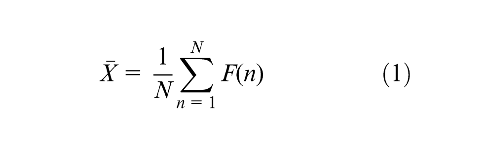
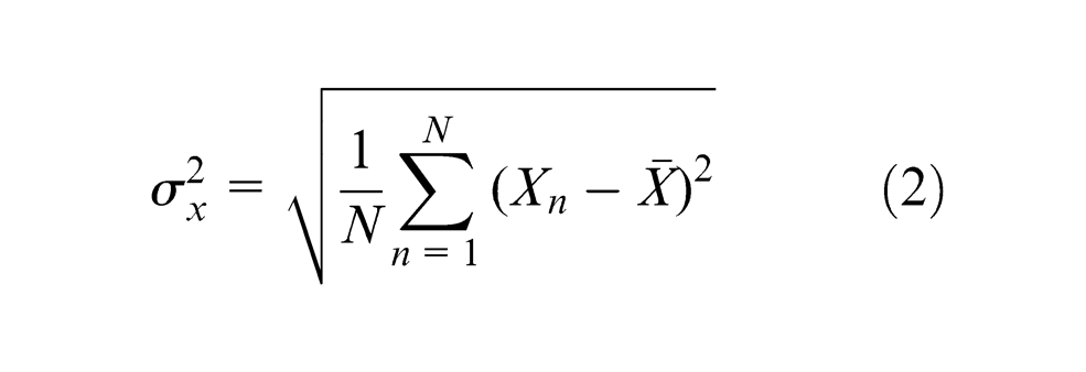
In conventional turning, static cutting force signal is used to compare the force components for sharp and worn cutting tool edge in the time domain. The static cutting force increases with wear levels such as crater and flank wear. Therefore, some basic signal-processing techniques are required to analyse raw signal in order to monitor cutting tool statues. For instance, mean value is the average value of a signal as expressed in equation (1) and standard deviation means the spread of the signal about the averaged value as expressed in equation (2)
and
Dynamic cutting force signal is used to indicate changes with increase in progressive wear or cutting tool breakage in conventional turning. The Fourier transform (FT) is commonly used to convert a time-domain signal into its frequency-domain equivalent. A time-domain signal shows how the amplitude of a signal changes with time, whereas a frequency-domain signal shows how the energy or power of a signal is distributed among the frequencies. In turning process, the spindle rotation frequency is normally identified in the fundamental frequency component, and the harmonics are normally related cutting process.
WTs are functions that you can use to decompose signals. Just as the FT decomposes a signal into a family of complex sinusoids, the WT decomposes a signal into a family of wavelets. Also, the WTs are an effective approach to detect transient features such as sudden changes or discontinuities in a signal. The main difference is that wavelets are well localized in both time and frequency domains, whereas the standard FT is only localized in frequency domain. So by taking account of the above advantages of WTs, it is employed to analyse cutting force signal to achieve real-time tool condition monitoring in machining single-crystal silicon wafer.
Experimental cutting trials
Experimental set-up
The machining trials were carried out using a three-axes, ultraprecision, diamond face turning machining with no cooling applied to either the workpiece or diamond cutting tool, as shown in Figure 1. The machine has an aerostatic bearing spindle and two direct current (DC) brushless permanent magnet linear motor drives along x- and z-axes. The resolution of the air bearing spindle is 0.045°, and the resolution of the x- and z-axes linear motor is 5 nm using the optical incremental encoder as feedback. A fast tool servo (FTS) is installed onto the linear motor for achieving a high-precision cutting tool positioning along z-axis.
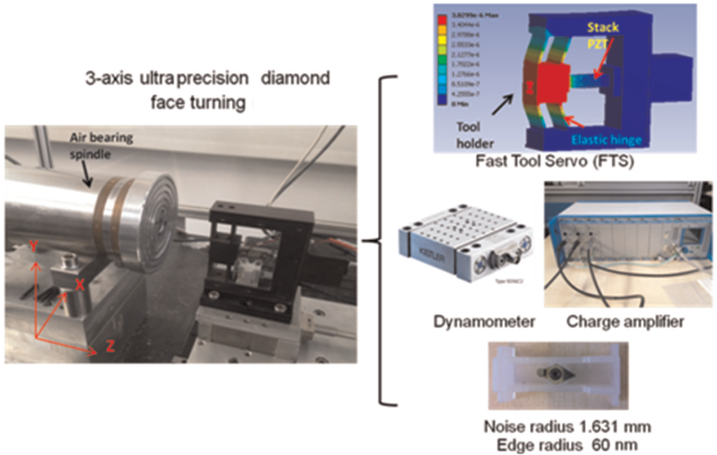
Schematic models of experimental set-up on three-axes ultraprecision diamond face turning machining.
Workpiece and diamond tools
The workpiece material was single-crystal, silicon wafer, 50 mm in diameter and 10 mm in thickness, firmly vacuum chucked on the air bearing spindle. To avoid cutting the centre of the workpiece where the cutting speed approaches to 0, the centre area of the wafer with diamond of 7 mm has been removed before experiment. Based on the understanding of the previous research findings, the round-nosed diamond cutting tool was quite appropriate in machining brittle material in ductile mode, silicon in particular. So the round-nosed diamond tool made of natural, single-crystal diamond purchased from Contour Fine Tooling, with the nose radius of 1.631 mm and the edge radius of 60 nm and the rake angle of 0° was used in the cutting trials.11,12
Cutting condition and forces measurement
The machining parameters selected in this cutting trials are given as follows: depth of cut (ap) = 10 μm, feed (f) = 5 mm/min and constant cutting speed (Vc) = 100 m/min. The experimental response was measured in terms of cutting distance (km). The total cutting distance achieves 9 km, being equivalent to number of 18 cuts, has been implemented in order to assess for tool condition. Cutting forces were measured using the Kistler MiniDyn 9256b located beneath the tool holder, as shown in Figure 1. The cutting force signals were collected through the NI DAQ 9234 card, and the sampling frequency was set as 4000 Hz to observe the frequency range of 0–2000 Hz.
Results and discussion
Cutting forces analysis in both time and frequency domains
Tool condition monitoring can be implemented by observing the cutting force signals regarding their static and dynamic signal components. Figure 2 depicts the cutting forces and radial forces with the cutting distance in diamond turning the silicon wafer. The radial forces slightly increase with the cutting distance and then followed by some fluctuations after the cutting distance of 5 km, probably indicating the unsteadiness of the cutting process or even the tool wear. Meanwhile, the cutting forces almost remain constant throughout entire cuts. So it is quite unreliable to develop a diamond cutting tool condition–monitoring system only based on the static force signal component analysis, as plotted in Figure 2. In order to investigate the critical dynamic force signal components, fast Fourier transform (FFT) was employed to convert time-domain signal into frequency-domain signal in Figure 3. The comparison of the cutting force and radial force signal in frequency domain has been made between the first and the last cut. It can be observed that certain frequency components increase drastically with the cutting distance, in particular the frequency component of 400 Hz for the radial force and the ones of 750 and 850 Hz for the cutting force, most likely due to the diamond tool condition changes during cutting process. To a certain degree, Fourier analysis can be the most commonly used mathematical technique to view signal in the frequency domain to assess the tool conditions. It has the great advantage of providing information on the spindle rotating speed, the tool pass frequency and the chip formation. However, time information is lost in the frequency domain after conversion. Furthermore, FT is less useful in analysing non-stationary signal or transient signal, which could impose restrictions on its function in machining application where the cutting force abruptly changes when cutting tool engaging with workpiece or when cutting tool tip breakage. Therefore, further investigations are required by analysing the cutting force signals based on wavelet analysis technique in order to overcome the limitation of FT.
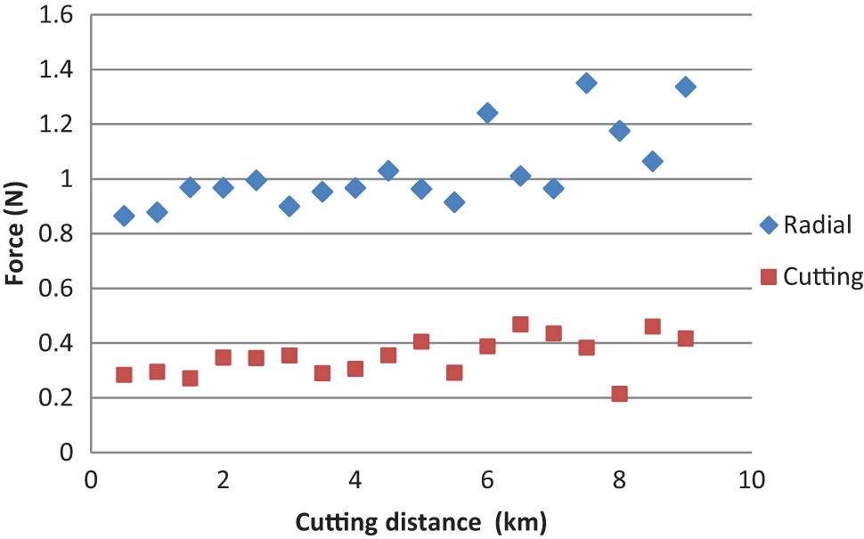
Cutting and radial forces with cutting distance on machining silicon wafer with diamond cutting tool.
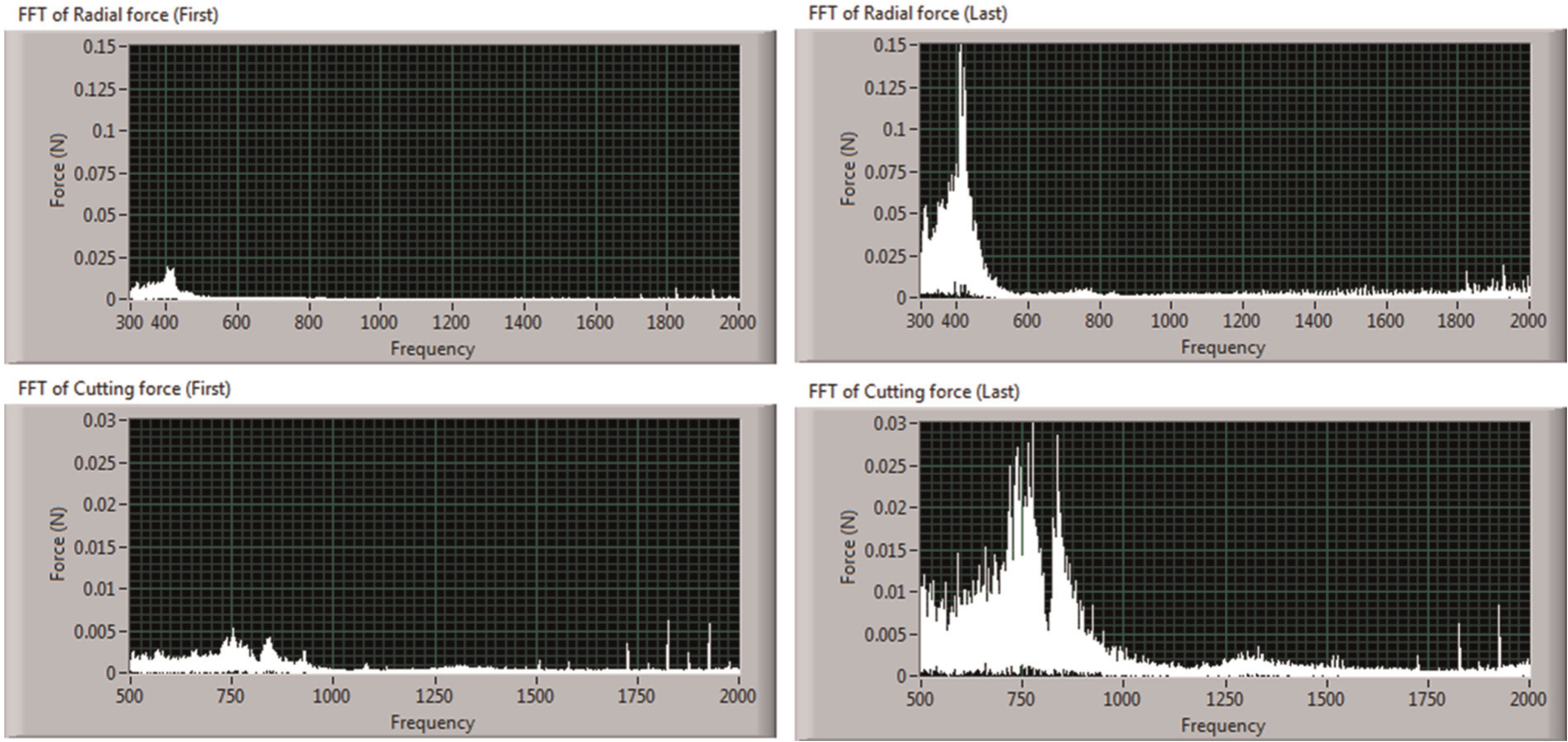
Comparison of the radial force (top two graphs) and cutting force (bottom two graphs) in frequency domain between first and last cut.
WT analysis on cutting forces
In the WT analysis, the Daubechies wavelet (dB3) is sensitive for the detection of abrupt frequency change in a signal and therefore was employed to decompose a raw cutting force and radial force signals into four levels. 13 Figure 4 shows force signal analysis procedures to find out the correlation between tool wear characteristic and cutting distance based on WT analysis. First, the raw radial force signal (Sraw) is decomposed into the approximation (a1) and details (d1, d2, d3 and d4) as described in Figure 4. Second, the peaks and valleys from the decomposed signal are extracted and its standard deviation is calculated. Finally, the tool condition changes are correlated with the cutting distance in order to monitor the diamond tool condition in real time.
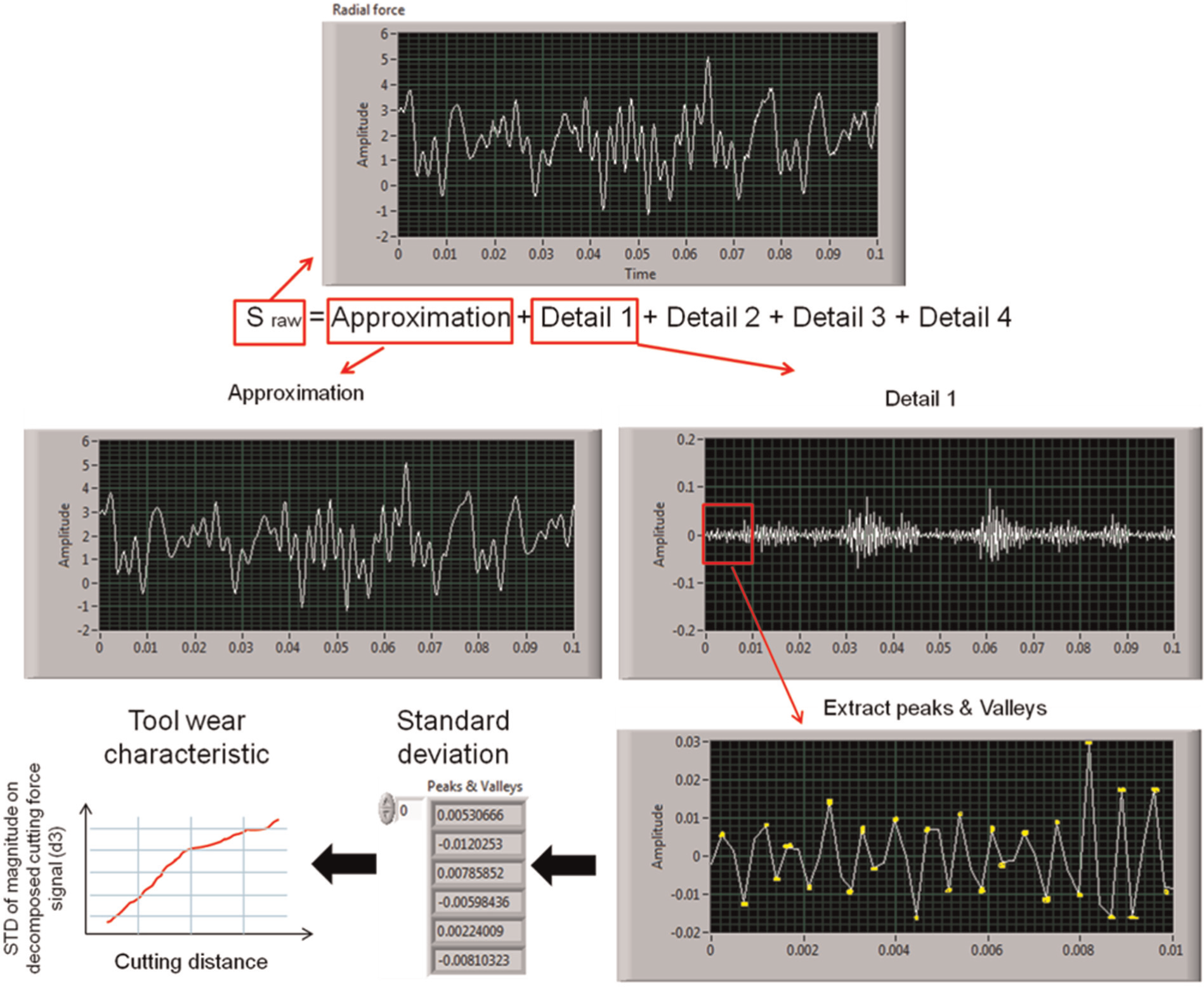
Signal processing to correlate tool wear characteristic with cutting distance using wavelet transform (dB3, level4).
Figure 5 shows the proposed signal-processing technique based on the standard deviation of magnitude on decomposed cutting force signal and radial force signal using the db3 wavelet analysis in machining single-crystal silicon. The results have shown that both the standard deviation of magnitude on decomposed cutting force signal and radial force signal increase with the cutting distance, as shown in Figure 5. It can be observed that both the standard deviation of magnitude on decomposed cutting force and radial force almost keep the same level till the cutting distance of 3.8 km; however, it dramatically increases after it that would imply the micro-fracture on the diamond tool tip. In order to validate the above experimental results, the other experiment was carried out using the second new diamond cutting tool in machining aluminium alloy, as shown in Figure 6. The results show that the standard deviation on decomposed cutting force signal and the radial force signal remains almost the same level with the cutting distance. This means that the second diamond cutting tool remains consistently superior with the cutting distance of up to 8 km in machining aluminium alloy.
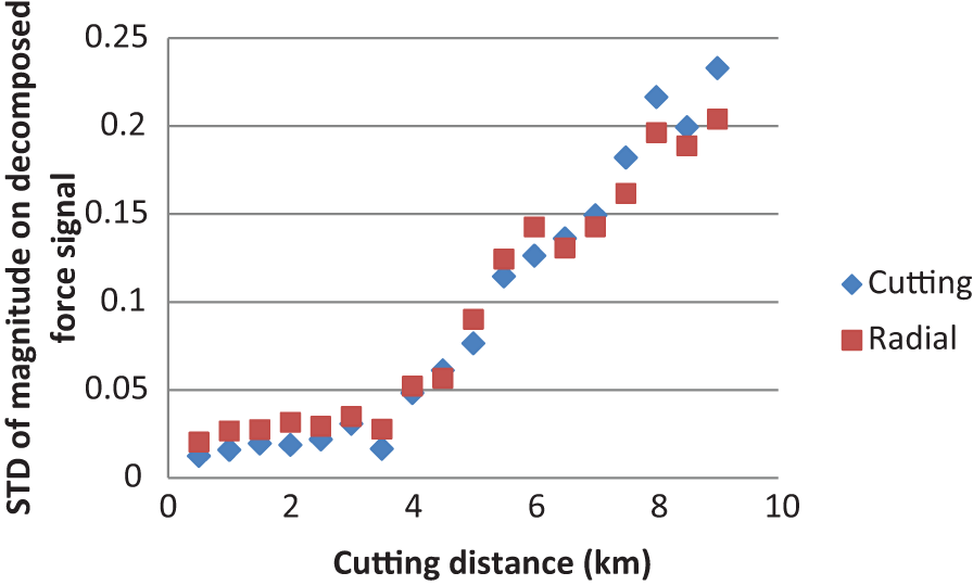
Relationship between standard deviation on decomposed cutting force signal and the radial force signal with the cutting distance in machining single-crystal silicon.
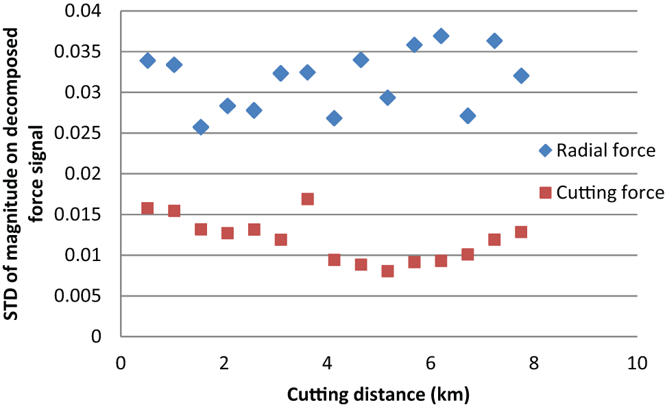
Relationship between standard deviation on decomposed cutting force signal and the radial force signal with the cutting distance in machining aluminium.
SEM observations on tool wear
The SEM photographs were taken after certain cutting distance to detect flank wear, micro-chipping and micro-fracture as normally observed in initial tool wear that could eventually lead to tool failure and cause unacceptable surface roughness on workpiece. The diamond tool was observed intermittently with an SEM at intervals of the cutting distance of 4.5 km. Figure 7(a) is an SEM photograph taken after the cutting distance of 4.5 km, showing the micro-fracture and the flank wear on the rake and flank region, respectively. It is also observable that the cutting edge becomes less sharp compared to the unused region, and the maximum width of the flank wear land is 18.5 μm. Figure 7(b) is the other SEM photograph taken after the cutting distance of 9 km. There is no crater wear observed in rake region, and the flank wear increases up to 39.8 μm. 14 The above observations indicate that the diamond tool wear with the cutting distance up to 9 km is still in the steady process. The results obtained from the SEM photographs demonstrate the possibility of condition monitoring on the initial wear of the diamond tool using the proposed signal processing based on the standard deviation on decomposed cutting force signal and the radial force signal.
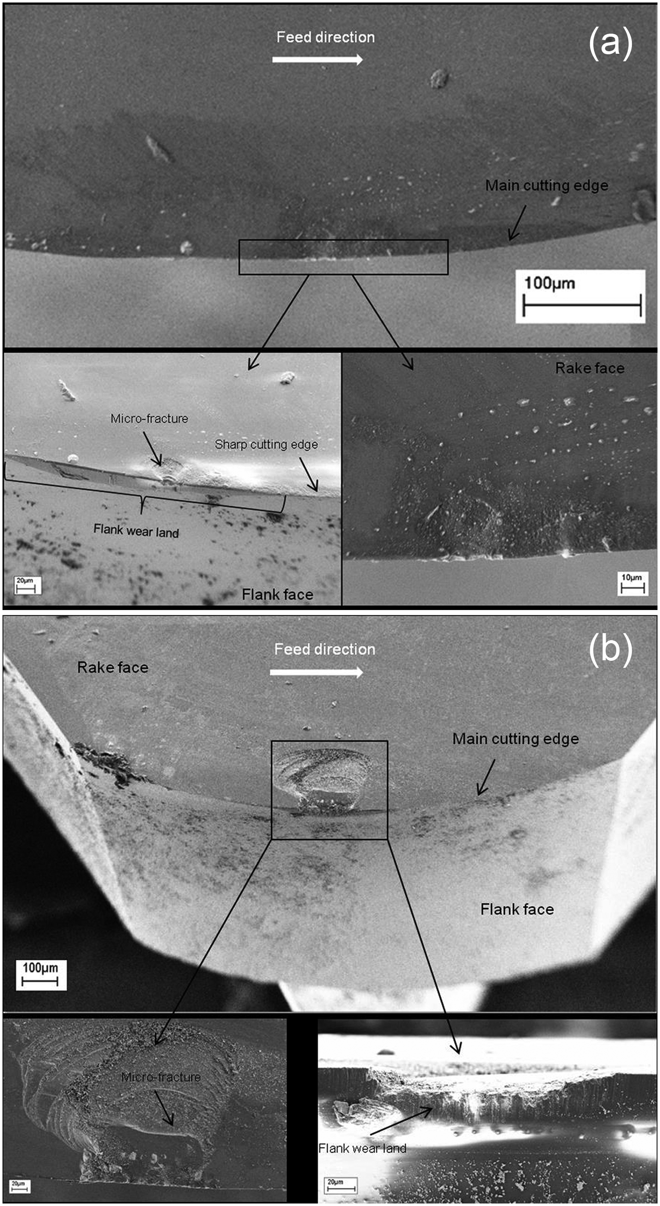
SEM photograph of the cutting edge taken after (a) 4.5 km and (b) 9 km to observe condition of diamond tool.
Conclusion
Diamond tool wear characteristics in machining single-crystal silicon were investigated by analysing the cutting forces and their correlations, supported with the SEM photographic observations undertaken after certain cutting distance. Both the cutting forces and the radial forces are analysed using the db3 wavelet (Level 4). The results show that the standard deviation of magnitude on both the decomposed cutting forces and radial forces have a correlation to the flank wear and the micro-fracture of the diamond tool as shown in Figure 5 in machining single-crystal silicon. Furthermore, the results observed from the SEM photographs show significant flank wear, less sharpness on the cutting edge and even micro-fracture on the diamond tool. However, there is no crater wear observed at the tool rake region until the total cutting distance of 9 km.
Footnotes
Acknowledgements
The authors would like to thank Mr Andrew Cox at Contour Fine Tooling (CFT) Ltd for his technical support and stimulating discussions.
Declaration of Conflicting Interests
The author(s) declared no potential conflicts of interest with respect to the research, authorship, and/or publication of this article.
Funding
The author(s) received no financial support for the research, authorship, and/or publication of this article.