
Abstract
Ferrous materials are widely used in the mould industry because of their excellent properties. However, ferrous materials are regarded as difficult-to-cut materials for diamond turning due to their affinity for diamond. The resulting catastrophic tool wear leads to high machining costs in ultraprecision turning. The unpaired d-electrons in the workpiece are regarded as the dominant element causing catastrophic diamond wear during the turning. However, an insightful method for unpaired d-electrons in existing assisted machining schemes is still lacking. As a type of diamond tool, polycrystalline diamond (PCD) tools are inexpensive to appropriately carry out wear experiments. Therefore, in this study, a novel assisted method based on a magnetic field (MF) was applied to suppress the PCD tool wear. Experimental results demonstrated that the MF-assisted machining can reduce the flank wear of PCD tools by 30.6%. The spin polarisation of d-electrons by the MF was the dominant mechanism inhibiting the chemical reaction and graphitisation, and thus suppressing the PCD tool wear. Simultaneously, the suppression of machining system vibration by the Lorentz force also had a positive effect on the suppression of the PCD tool wear. The innovative method provides an assisted machining scheme to inhibit the catastrophic wear of PCD tools.
Introduction
Diamond turning is a typical micromachining method. It is an ultraprecision machining method and is increasingly employed in precision engineering industries, including defence, aerospace, automotive, and medical engineering industries.1,2 Ferrous materials, especially iron-based metals, are widely employed in industrial production because of their excellent mechanical properties. However, because of their affinity for the elements of C and Fe, diamond tools applied in turning of ferrous materials can easily cause catastrophic wear of the diamond tools. 3 The catastrophic wear limits its use in industrial production as well as scientific research. Some typical methods of diamond machining for the latter (e.g. the fast/slow tool servo) usually employ aluminium or copper alloy. 4 Wang et al. 3 reported that the catastrophic wear is caused by a combination of wear forms, such as adhesion, fatigue, abrasion, diffusion, oxidation and graphitisation. Among these wear forms, the catastrophic wear mainly originates from graphitisation, which largely reduces the service life of diamond tools and consumes a large amount of diamond. Therefore, the suppression of diamond tool wear in turning ferrous materials is a crucial technology in ultraprecision machining.
To suppress the diamond tool wear, numerous assisted methods have been employed in the field of diamond turning of ferrous materials, such as surface nitridation 5 and ultrasonic-vibration-assisted method. 6 Saito et al. carried out electron-beam-excited plasma surface nitridation-assisted turning experiments and achieved a machined surface with a peak-to-valley (PV) value of 55 nm after turning 542 m of a diamond tool. 5 Lee et al. 7 carried out ultrasonic vibration combined with ion-implantation-assisted cutting experiments and achieved a surface roughness Ra of 137.4 nm after cutting 350 m of a diamond tool. Zhang et al. 8 carried out ultrasonic vibration combined with a chemical-surface-treatment-assisted cutting experiments and achieved a surface roughness Sa of 23 nm after cutting 40 m of a diamond tool. Zhang et al. carried out ultrasonic vibration combined with oxygen-shielding-assisted cutting experiments and achieved a surface roughness Ra of 64 nm after cutting 50 m of a diamond tool. 9 Studies over the past 5 years have provided important information on the wear suppression methods of diamond tools. However, these schemes cannot be widely applied in industrial production because of a severe diamond tool wear.
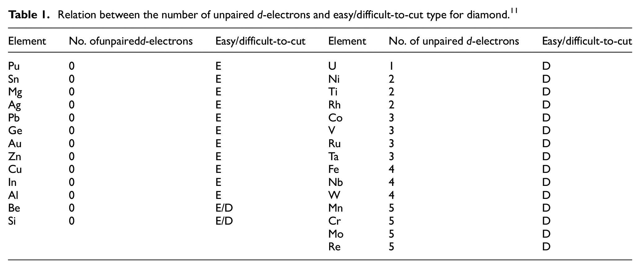
Brinksmeier and Preuß concluded that the catastrophic wear separates some typical materials into easy-to-cut and difficult-to-cut diamond tools, as shown in Figure 1. 10 According to the distributions of these materials in the periodic table of elements, the hard-to-cut materials are mainly distributed in the left half of the table. Therefore, it is of interest to elucidate the dominant cause of catastrophic wear to develop a feasible diamond tool wear suppression method. The experimental results of Poul et al. 11 demonstrated that unpaired d-electrons have a dominant role in catastrophic wear, as shown in Table 1. The unpaired d-electrons lead to affinity for diamond and iron. Therefore, an insightful method for unpaired d-electrons to suppress the diamond tool wear is required.
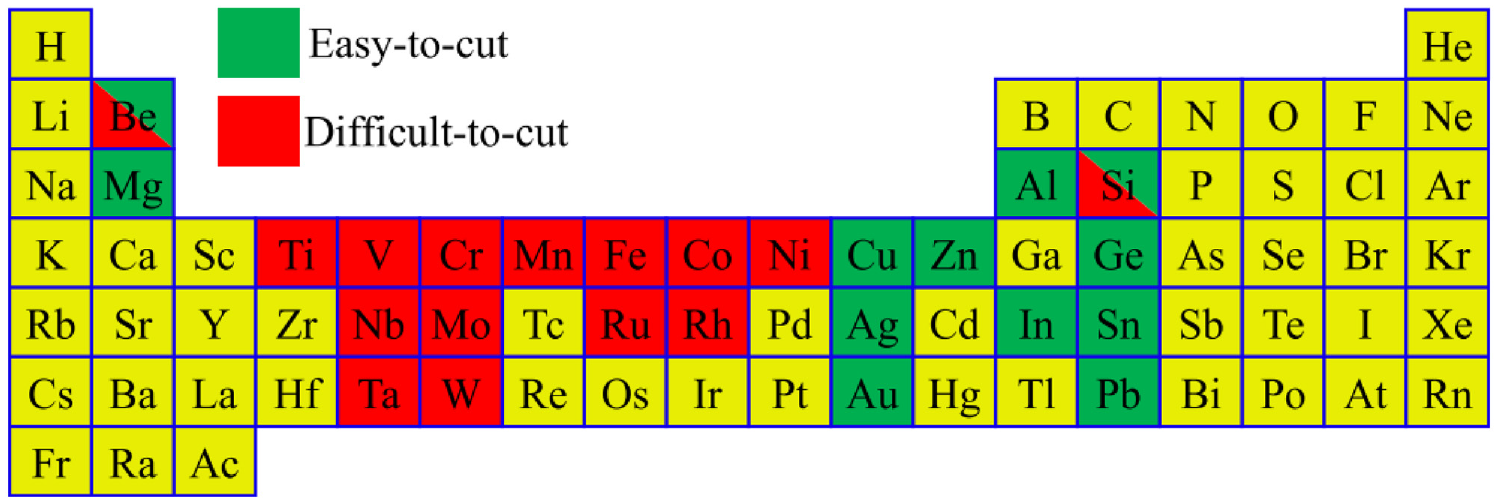
Typical materials, easy-to-cut and difficult-to-cut, for diamond tools in ultraprecision turning. 10
Relation between the number of unpaired d-electrons and easy/difficult-to-cut type for diamond. 11
Magnetic field (MF), as a cleaner energy, is a common form used in assisted machining schemes, which can suppress the tool wear and machining vibration. 12 Regarding the traditional turning, Nakano studied the influence of the MF on the tool wear in the turning of steel. The experimental results showed that MF-assisted turning could reduce the flank wear of tools and improve the surface roughness of the machined workpiece. 13 Patwari et al. 14 studied MF-assisted turning of a preheated mild steel. The experimental results showed that this method can enhance the tool life and improve the machined surface roughness by 20%. Through experiments, Zhang et al. concluded that MF-assisted turning can reduce the cutting force and tool wear and improve the surface roughness of the machined workpiece. 15 Studies over the past 20 years demonstrated that MF-assisted turning is a feasible assisted method for machining of ferrous materials. In traditional turning, an MF is usually applied to pretreat tools to obtain tools with higher cutting performances. Various forms of MF pretreatment of tools are employed, including alternating and pulse MFs.16,17
Compared to traditional turning, ultraprecision turning is characterised with a qualitative change and mainly employs diamond tools.18,19 Diamond is a typical diamagnetic material that is not magnetised by MF. Therefore, further experiments are needed to study the influence of the MF on the diamond tool wear in ultraprecision turning of ferrous materials. However, both theoretical and experimental studies are lacking. The properties of unpaired d-electrons can be affected by the MF. The unpaired d-electrons are the dominant cause of catastrophic wear. Therefore, MF is needed to provide an assisted turning method to suppress the diamond wear. Based on these results, an MF-assisted turning method was innovatively applied in this field. Based on a group of turning experiments and subsequent quantitative analyses, scientific explanations are provided for the observed phenomena.
Experiments
In this study, the MF was generated by two magnets, which were fixed by a fixture and could be disassembled and moved freely. The MF-assisted turning experimental setup is shown in Figure 2. Notably, the placement of the magnet can change the strength of the MF and direction of the magnetic induction lines (MIL). The form of the MIL was used to distinguish the different MFs in this study. In this experiment, three placement modes of magnets were applied to obtain three different types of MIL. Two parallel magnets can generate two types of MFs. When the direction of the MIL is parallel to the feed direction on the workpiece surface, the MF generated by this type of MIL is denoted as NS-type MF (see Figure 3(a)). When the direction of the MIL is parallel to the feed direction on the workpiece surface, the MF generated by this type of MIL is denoted as NN-type MF (see Figure 3(b)). The torus-shaped magnets can generate an MF type referred to as circle-type MF, in which the direction of the MIL is perpendicular to the direction of the feed on the workpiece surface (see Figure 3(c)).
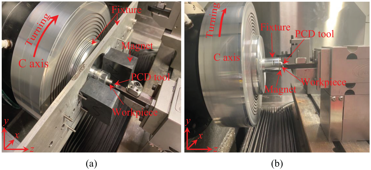
Experimental setup to generate (a) NN-type MF, NS-type MF and (b) circle-type MF.
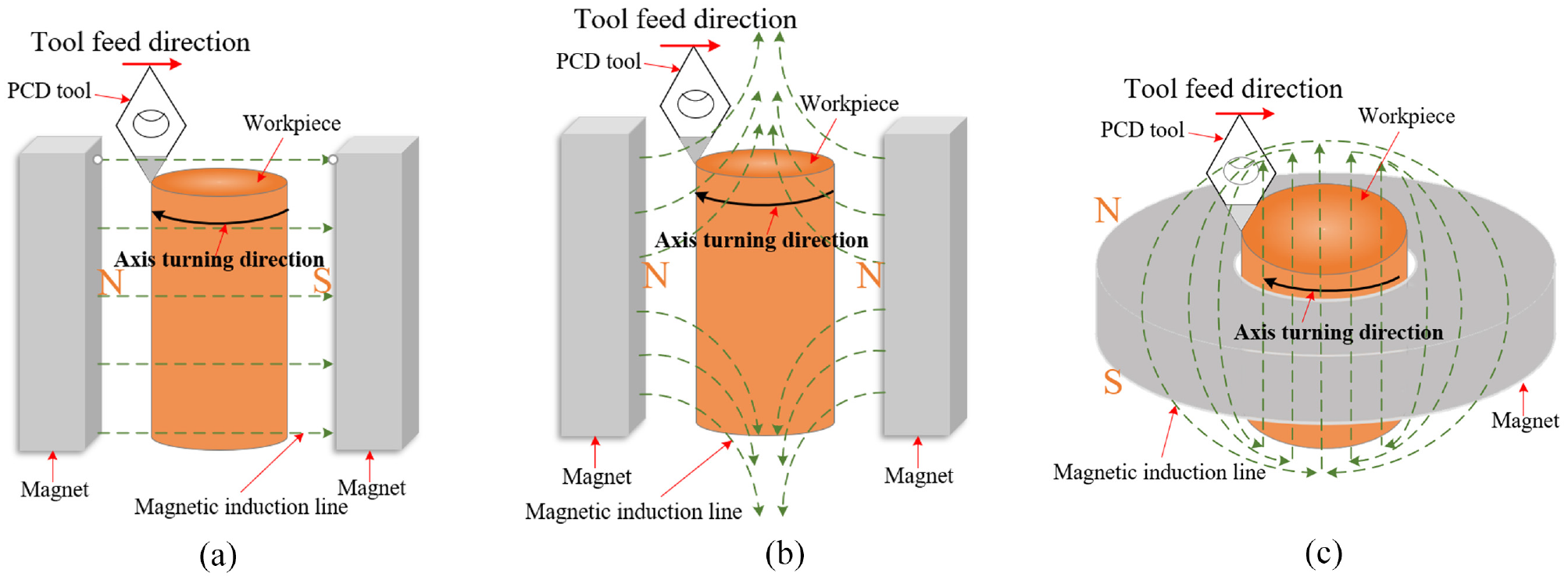
Schematic of the direction of MIL and feed on the workpiece surface within the (a) NS-type MF, (b) NN-type MF and(c) circle-type MF.
The MF with a specific strength can be obtained by adjusting the distance of the magnets or magnet type in the turning experiments. As shown in Figure 2(a), this state can provide NN-type and NS-type MFs. The strength of the NS-type uniform MF can be measured directly (0.08 T) because the direction of the MIL is constant between the two magnets, as shown in Figure 3(a). The strength of the NN-type MF cannot be measured directly because the direction of the MIL changes between the two magnets, as shown in Figure 3(b). These two types of MF are generated in similar manners. One type of MF can be converted to another by simply switching the NS poles of the magnet. A torus-shape magnet is applied to obtain the circle-type MF. The strength of the MF can be measured (0.08 T) on the surface of the workpiece because the MIL is gathered inside the workpiece, as shown in Figure 3(c).
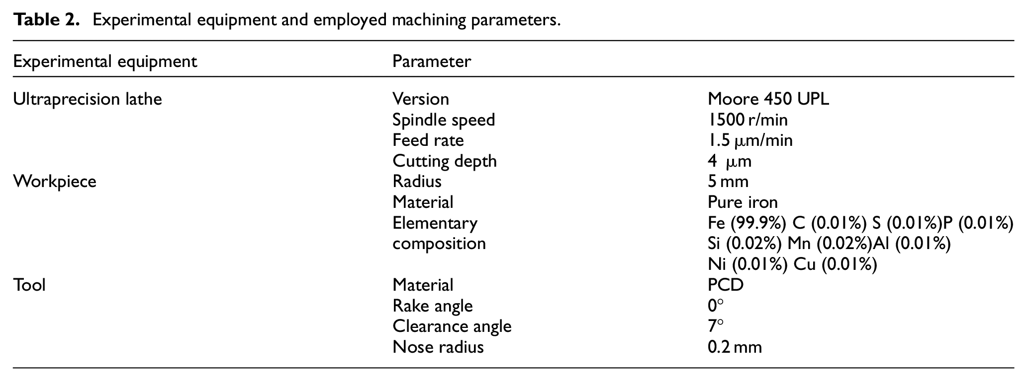
The experimental equipment and employed machining parameters are presented in Table 2. A polycrystalline diamond (PCD) tool is used. The cost of the PCD tool is approximately 1/50 of that of a single-crystal diamond tool. The wear mechanism is similar to that in cutting ferrous metals. Therefore, it is appropriate to use PCD tools to study the mechanism of catastrophic wear of diamond tools in the turning of ferrous materials. The turning distance of the diamond tool was calculated using an arithmetic fitting method. The spindle speed was 1500 r/min, while the feed rate was 1.5 mm/min.
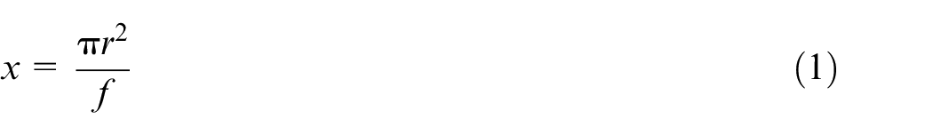
where x is the distance of turning (m), r is the radius of the workpiece (mm), and f is the feed rate (μm/min).
Experimental equipment and employed machining parameters.
According to Formula (1), the calculated actual turning distance is 157 m.
Results and discussion
Influence of the MF on the PCD tool flank wear
Turning ferrous materials with single-crystal diamond tools can easily lead to a typical flank wear pattern, as shown in Figure 4(a). The PCD structure is formed by a sintered fine-grain diamond with different orientations. Therefore, PCD tools are not as regular as single-crystal diamond tools in terms of cutting-edge geometry. The flank wear pattern of PCD tools is not as regular as that of single-crystal diamond, as shown in Figure 4(b). However, the flank wear of diamond tools exhibits a skew crescent-like wear pattern and groove-like wear marks. Figure 5 shows the generation mechanism of the skew crescent-like morphology of the diamond tool flank wear. The left or right skew of the crescent-like wear pattern is related to the feed direction. As shown in Figure 5, segment A1 of the cutting edge contacts more materials than segment B1; therefore, more wear will be generated during the turning. Thus, in the corresponding flank wear area of the diamond tools, a larger wear area A and smaller wear area B will be generated. Moreover, groove-like wear marks are considered to be generated by etch-like features during the graphitisation of a diamond surface. 20
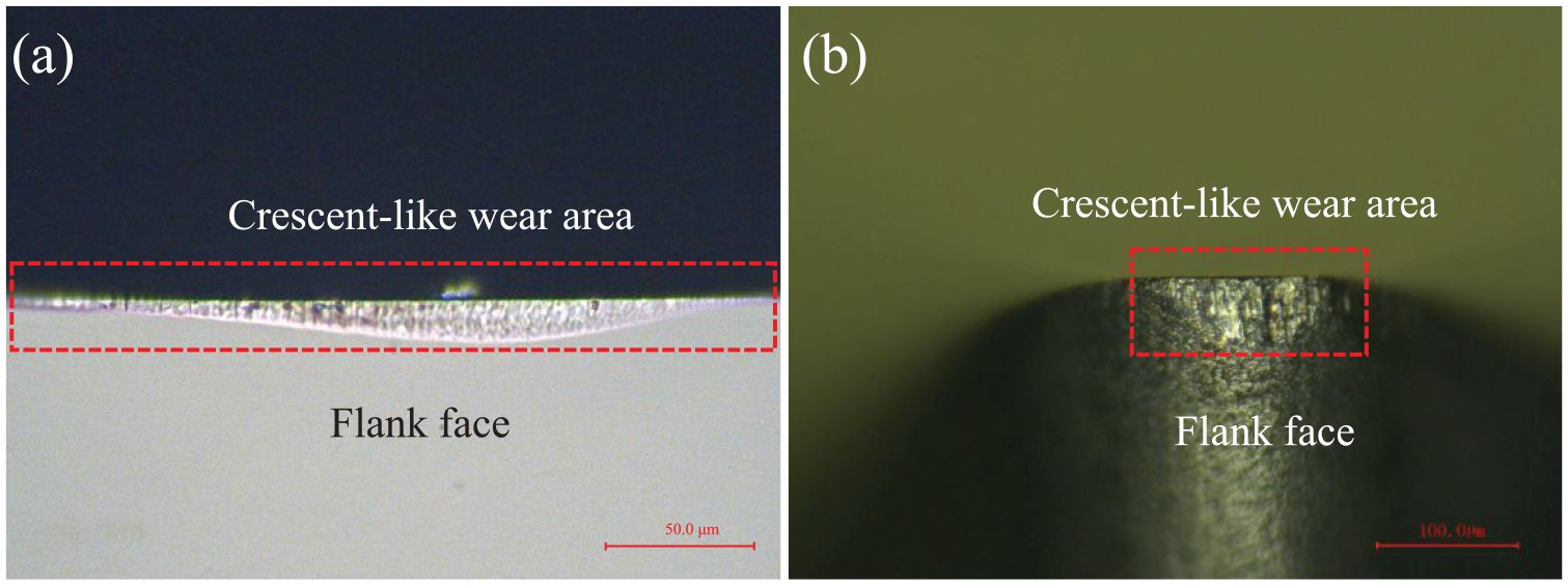
Typical flank wear morphology of (a) a single-crystal diamond tool and (b) PCD tool after turning pure iron.
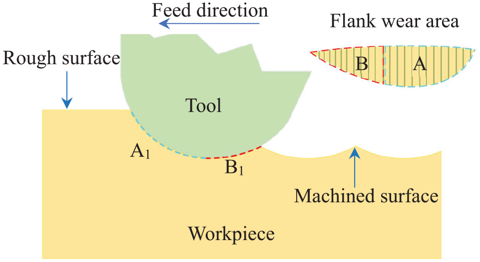
Generation mechanism illustration of the skew crescent-like wear morphology on the diamond tool flank face.
The maximum widths of the flank wear of the PCD tools in the cases of non-MF-assisted turning and MF-assisted turning are shown in Figures 6 and 7, respectively. According to the experimental results, the flank wear of the diamond tools maintained the original crescent-like wear pattern and had groove-like wear marks when the MF was applied. According to the maximum widths of the flank wear of the PCD tools, the flank wear of the PCD tool is largest without MF. The maximum width is 143.8 μm. The smallest flank wear of the PCD tool could be obtained within the NS-type MF. The maximum width was 99.8 μm. Compared to that in non-MF-assisted turning, the maximum width of the flank wear of the PCD tool was reduced by the MF-assisted turning. It can be calculated that the maximum widths of the flank wear of the PCD tool were reduced by 4.1%, 30.6% and 23.9% within the NN-type, NS-type and circle-type MF-assisted turning, respectively.
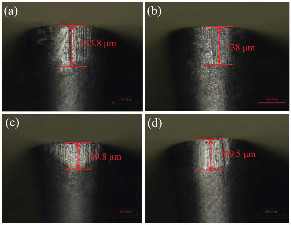
Flank wear micrographs of the PCD tool within different MF types: (a) without MF, (b) NN-type MF, (c) NS-type MF and (d) circle-type MF.
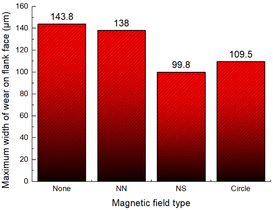
Maximum widths of wear on the flank face of the diamond tool within different MF types.
The MF-assisted turning can significantly suppress the flank wear of PCD tools. Graphitisation is a well-known chemical wear of diamond tools in the field of ultraprecision turning of ferrous materials. Therefore, MF-assisted turning is a suitable method to inhibit the chemical reaction. However, the interaction energy between the MF and chemical particles such as ions, molecules, and atoms is usually only 10−4∼10−6 times the thermal motion energy of particles. However, the MF can affect the electron spin state, which affects the chemical reactions, mainly as the spin properties of the d-electrons are affected by the MF. Studies on the spin of electrons within an MF are challenging, whereas quantum mechanics provides a suitable calculation for one electron. If an electron in a certain domain is placed in a uniform MF along the x direction and the electron spin is upward at t = 0, the state wave function of the system at t > 0 is defined as 21 :
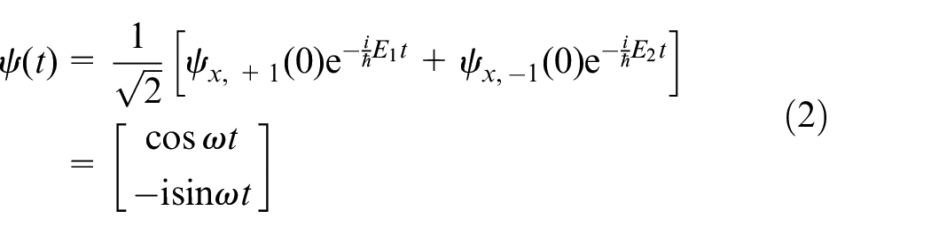
where
According to Formula (2), the measured average values of each component of the electron spin operator can be obtained at t > 0.
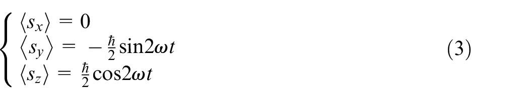
Considering the z direction as an example,

where ΔG is the Gibbs free energy, ΔH is the enthalpy change, T is the temperature, and ΔS is the entropy change.
The Gibbs free energy can be used to determine the direction of the chemical reaction. The chemical reaction between the diamond and graphite proceeds according to the thermodynamics:
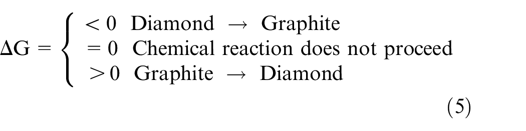
Therefore, the diamond graphitisation can be suppressed owing to the increased Gibbs free energy. Because the chemical reactions also depend on the entropy, the MF can promote the spin polarisation of d-electrons, which in turn leads to an ordered system. In particular, unpaired d-electrons spontaneously magnetise to form domains in ferromagnetic materials. Therefore, the magnetic domains are the minimum unit to analyse the polarisation of the electron spin in pure iron. The effect of the polarisation of magnetic domains can change the system from disordered to ordered, as shown in Figure 8. The entropy of a system can be decreased in an ordered state. Therefore, at this time, ΔS < 0 leads to ΔG becoming larger to suppress the diamond graphitisation wear.
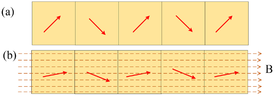
Schematic of the magnetic domain polarisation from the (a) disordered state (without MF) to the (b) ordered state (within the MF).
Influence of the MF on the PCD tool rake wear
The rake wear of PCD tools must be considered from another perspective. There is a significant difference between the flank wear and rake wear of the PCD tools. The morphology of the rake face of the PCD tools was imaged using scanning electron microscopy (SEM), as shown in Figure 9. In the absence of MF, the PCD tool rake face exhibited a microfracture (see Figure 9(a)). This did not appear within the MF (see Figure 9(c), (e) and (g)). The generation of microfractures was induced by machining vibration during the turning process. Different surface morphologies can be generated with different magnitudes of vibration. Furthermore, the trends of the surface roughnesses and vibration magnitudes were consistent. Therefore, the surface roughness (Sa) was used to evaluate the magnitude of vibration. A ravine surface could be generated in the absence of MF, as shown in Figure 9(i), whereas a smooth surface can be generated within an MF, as shown in Figure 9(j) to (l). Therefore, the machined surface morphology demonstrated that the MF can effectively reduce the vibration of the system during turning.
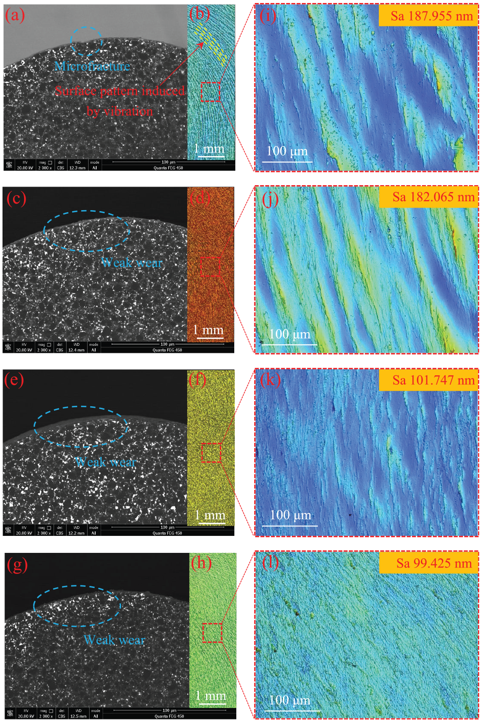
Rake wear of PCD tools and machined surface morphology within different MF types: (a and b) without MF, (c and d) NN-type MF, (e and f) NS-type MF, and (g and h) circle-type MF. (i–l) Partial enlarged views of (b, d, f and h), respectively.
The vibration suppression in the MF-assisted turning can be further analysed using the Lorentz force. The Lorentz force is the main reason for the weak vibration of the machining system. An eddy current is generated when a conductive metal rotates within the MF inside the conductor. The Lorentz force is generated by the eddy current, which can generate own MF in the direction opposite to that of the external MF. Figure 10 illustrates the MIL directions of the external MF and eddy-current-induced MF in the two MF-assisted methods, which significantly suppress the diamond tool flank wear. The direction of the Lorentz force can be obtained from the direction of the MIL through the left-hand rule. Under the NS-type MF-assisted turning, the eddy current is generated in the yoz plane and the direction of the Lorentz force is determined by the left-hand rule. Therefore, the vibration in the yoz plane can be suppressed by the Lorentz force (see Figure 10(a)). Under the circle-type MF-assisted turning, the eddy current is generated in the xoy plane. Therefore, the vibration in the xoy plane can be suppressed by the Lorentz force (see Figure 10(b)). The Lorentz force suppresses the vibration of the plane on which it is located, to not only suppress the vibration of the machining system but also obtain high-quality machined surfaces.
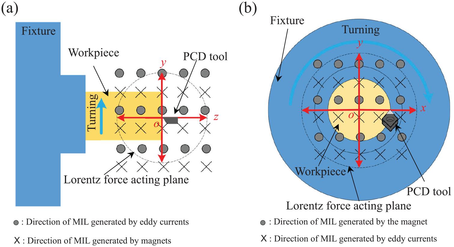
Schematic of the plane vibration suppression by the Lorentz force: (a) xoz plane within the NS-type MF and (b) xoy plane within the circle-type MF.
Influence of the MF on the machined surface integrity and chip generation mechanism
The MF-assisted turning also has a significant influence on the integrity of the machined workpiece surface. As a single machined surface could not truly reflect the quality of the machined workpiece surface, five 0.44 mm × 0.33 mm regions were selected on the machined surface to carry out a surface roughness measurement by a white light interferometer (see Figure 11). As shown in Figure 11, the surface roughness of the workpiece gradually increased upon approaching the centre area. According to the comparison of the surface roughnesses of the five regions (see Figure 12), the surface integrity of the workpiece was best in the circle-type MF-assisted turning. A surface roughness of 42.9 nm can be obtained in the region of 0.44 mm × 0.33 mm. A surface roughness of 23.858 nm can be obtained in the region of 89 μm × 66 μm. Under NS-type MF-assisted turning, the surface integrity of the workpiece was also better than that of the workpiece in the absence of MF. In the NN-type MF-assisted turning, the surface integrity of the workpiece was slightly worse than that of the workpiece in the absence of MF. The surface morphology reflecting the surface integrity of the machined surface in the same position is shown in Figure 13, which demonstrates the effectiveness of the MF-assisted turning.
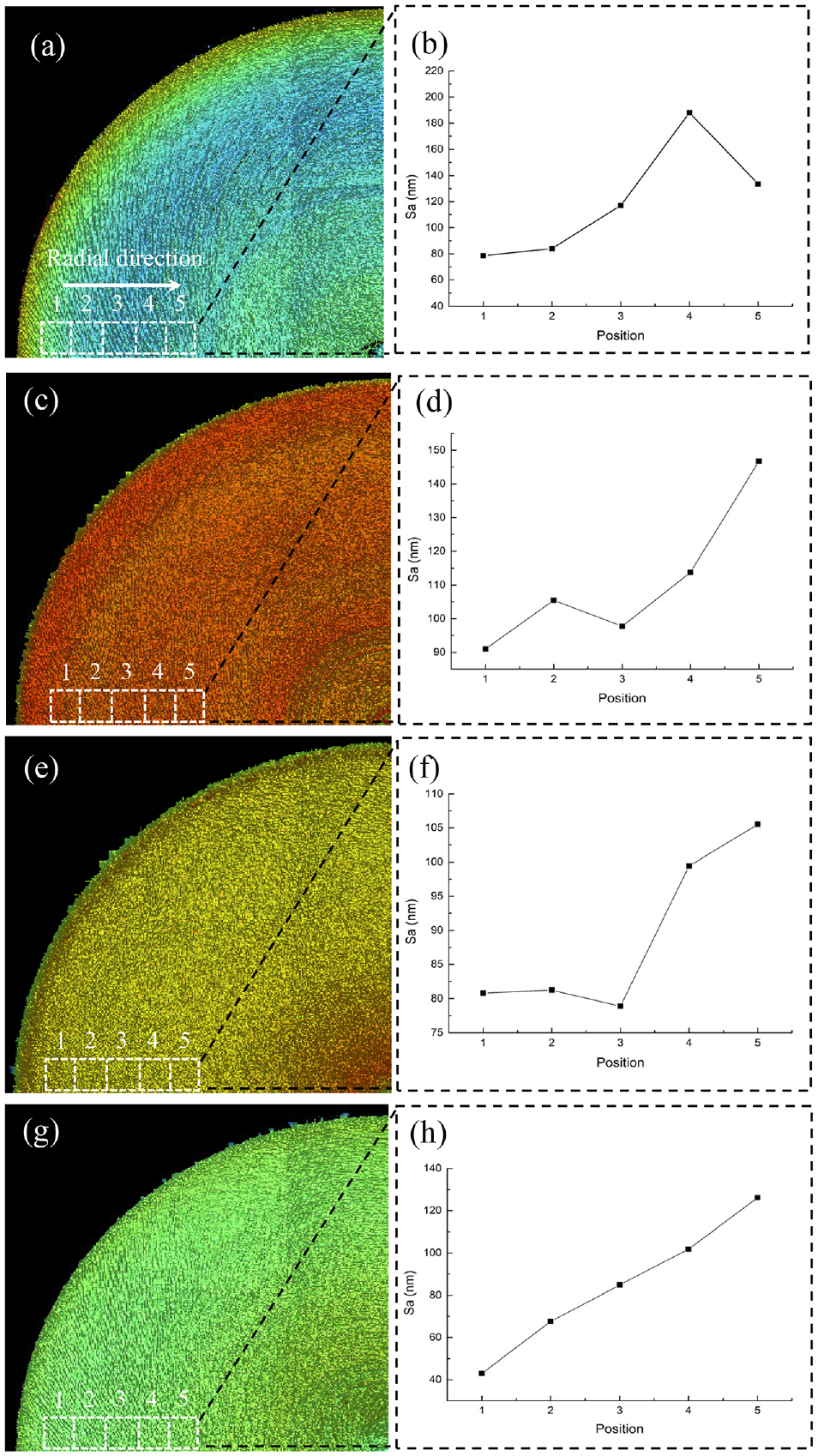
Roughness along the radial direction of the machined surface within different MFs: (a and b) without MF,(c and d) NN-type MF, (e and f) NS-type MF, (g and h)circle-type MF.
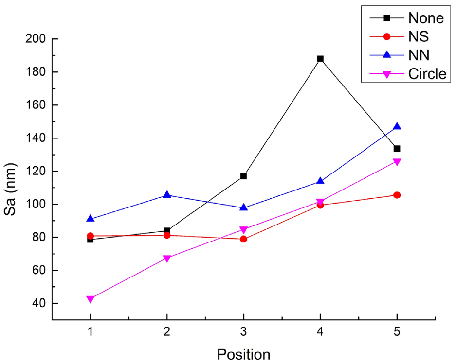
Roughness with respect to the radial position of the machined surface within different MFs (five positions in Figure 11).
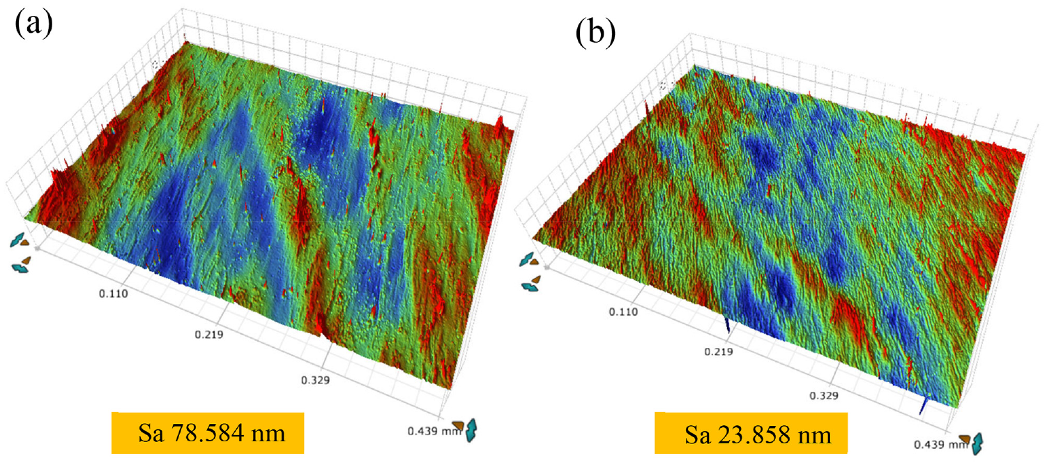
Three-dimensional morphology of machined surfaces obtained by a white light interferometer (a) without MF and(b) within the circle-type MF.
In addition, the degree of flank wear of the diamond tools can be verified by the surface integrity of the workpiece. The NN-type MF-assisted turning has a weak effect on the flank wear of PCD tools. Therefore, the reflection on the surface roughness is not better than that in the absence of an MF. However, both NS-type MF-assisted turning and circle-type MF-assisted turning have a significant suppressing effect on the PCD tool flank wear. The surface roughness of the machined workpiece is also better than that in the absence of MF. Therefore, the maximum width of the flank face wear of the PCD tool corresponds to the roughness of the machined surface. When the wear of the tool flank face was significantly suppressed, the workpiece surface integrity was improved and the machined surface roughness was reduced.
The generated chips can also reflect the integrity of the machined surface. Chips generated under different MF conditions were collected and observed. The shapes of the chips are shown in Figure 14. In the absence of MF, a small strip shape of B-type chips was generated with occasional A-type chips (see Figure 14(a)). A-type chips are regular compared to B-type chips, whereas they are not ideal for E-type chips. E-type chips appear more frequently, as shown in Figure 14(d). For example, E1, E2 and E3 are ideal chips, which implies vibration suppression in the machining process to easily generate high-quality surfaces. Furthermore, C-type chips, as shown in Figure 14(b), appear granular. The D-type chips, as shown in Figure 14(c), appear in a wide strip shape. This implies that the generation mechanism of the chips is changed by the MF, mainly as the different MF types and strengths can change the properties of ferromagnetic materials and affect the processing properties of the materials.
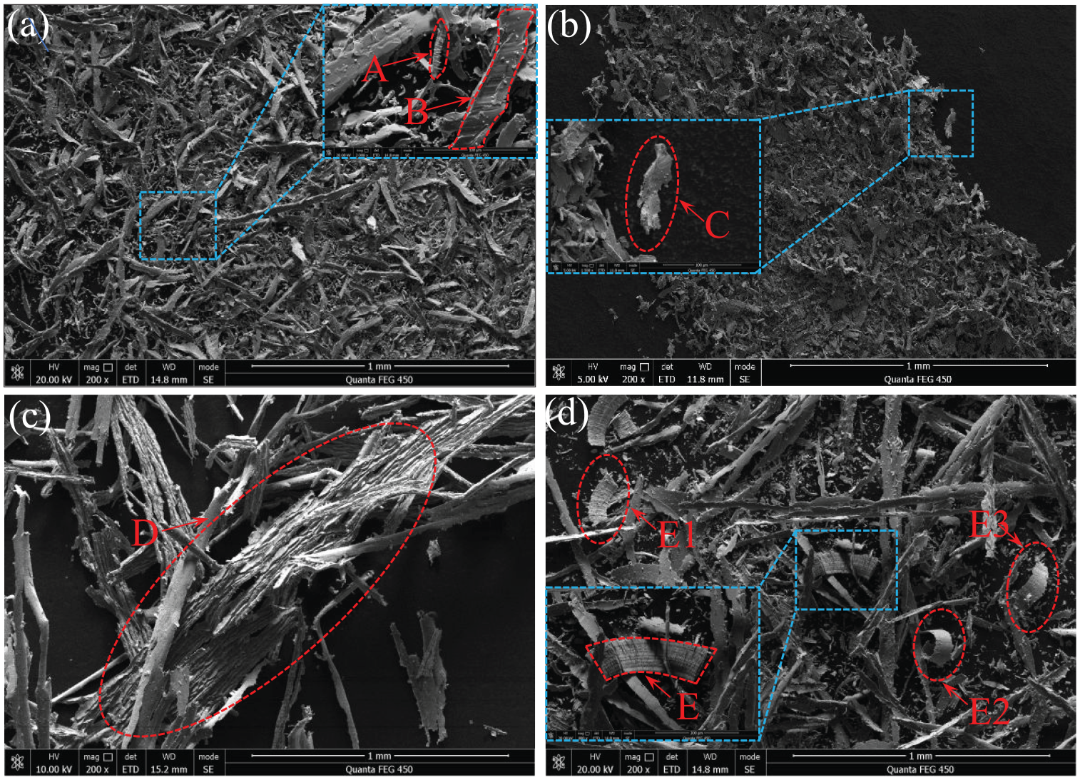
SEM images of the chip morphology within different MFs: (a) without MF, (b) NN-type MF, (c) NS-type MF and(d) circle-type MF.
In future analyses, as shown in Figure 10, the Lorentz force generated by the NS-type MF can be used to suppress the vibration in the oz and oy directions (axial and longitudinal vibrations, respectively). The Lorentz force generated by the circle-type MF can suppress the vibration in the ox and oy directions (lateral and longitudinal vibrations, respectively). The vibration during the machining process has a significant influence on the surface roughness and chip integrity. Therefore, the vibration suppression direction of the circle-type MF is conducive to machining high-quality surface and high-integrity chips. Thus, under the condition of minimum tool wear, the NS-type MF assisted the turning, whereas the best machined surface roughness and chip integrity cannot be obtained.
Conclusions
We evaluated the positive influence of MF on tool wear suppression in PCD turning ferrous materials and proposed a novel assisted scheme. The conclusions of this study can be summarised as follows.
The MF-assisted turning has a noticeable effect on the suppression of flank wear of PCD tools. The NS-type and circle-type MFs led to the most significant suppression of the flank wear of PCD tools, as shown by the experimental results, with reductions of 30.6% and 23.9%, respectively.
The d-electron spin polarisation had a dominant role in the mechanism of diamond tool wear suppression.
The Lorentz force acting on the xoy plane was larger than that acting on the xoz plane in suppressing the vibration of the machining system. This was the fundamental reason for the higher quality of the machined surface with the larger diamond tool flank wear under the circle-type MF.
The proposed method is among the first to introduce an MF into the suppression scheme of diamond tool wear in the turning of ferrous materials and consumes less energy than other assisted methods.
Footnotes
Declaration of conflicting interests
The author(s) declared no potential conflicts of interest with respect to the research, authorship, and/or publication of this article.
Funding
The author(s) disclosed receipt of the following financial support for the research, authorship, and/or publication of this article: The work described in this paper was supported by the National Natural Science Foundation of China (Grant No. U2013603, 5182 7901), the Shenzhen Natural Science Foundation University Stability Support Project (Grant No. 2020 0826160002001, 20200821110721002) and the Post-graduate Innovation Development Fund Project of Shenzhen University (Grant No. 315-0000470813).