
Abstract
The sintered alumina (Al2O3) ceramic materials featured with high temperature stability, excellent wear resistance, and high strength are highly in demand for various commercial applications. Alumina ceramics in the sintered state are difficult to machine owing to their high hardness. This research focuses on the study on the machinability of sintered alumina ceramic materials by using chemical vapor deposition diamond coating tools. Milling cutting tests are performed on a common 3-axis computer numerical control milling center. Four fluted tungsten carbide end mills with chemical vapor deposition diamond coating are utilized to machine alumina ceramics at different cutting speeds, feed rates, and widths of cut. The cutting process outcome is evaluated based on the machined surface’s finish, tool wear and life, the material removal rate, and the cutting force. It is found that the milling machining process for alumina ceramic materials using chemical vapor deposition diamond coating tools is feasible with adequate machining conditions, and the machining outcome largely depends on the cutting conditions. Two alumina ceramics parts are also fabricated to demonstrate the feasibility of proposed machining processes. The details of the machining experiments and the obtained results are presented in this article.
Keywords
Introduction
Alumina is a chemical compound of aluminum and oxygen with the chemical formula Al2O3, which commonly occurs in its crystalline polymorphic phase α-Al2O3. Sintered alumina (Al2O3) ceramics are one of the most widely used and studied advanced functional ceramic materials. It has many unique chemical, physical, and mechanical characteristics, including retention of strength and hardness at elevated temperatures. The major challenge of using the sintered alumina ceramics as functional industrial components is its difficulty of fabrication,; since sintered alumina ceramics are extremely difficult to cut.1,2
As it is known, alumina ceramics in its “green” state, or its pre-sintered state, can be machined into complicated geometric shapes with reasonable productivity by turning, drilling, and milling methods because of its relative “softness.” Usually, machined alumina ceramic components in the “green” state have to be sintered at a high temperature in order to achieve the desired mechanical, chemical, and electrical properties. However, up to 2% of the volume shrinkage and the geometric distortion of the ceramic components occur during its sintering. As a result, tight dimensional tolerances and high-quality surface finish are difficult to achieve. 3
Several machining methods such as ultrasonic machining, rotary ultrasonic machining, laser-assisted machining, and laser machining have been studied for sintered alumina ceramic materials. 4 The ultrasonic machining of ceramics uses the action of slurry, containing abrasive particles flowing between the workpiece and a tool vibrating at an ultrasonic frequency of 19–25 kHz, and an amplitude of 13–50 μm for hole making operation. 5 As the tool vibrates, the abrasive particles (grit) dispersed in the slurry strike the ceramic workpiece and remove small ceramic debris fracturing from the surface. Low machining accuracy and high tool wear are existing issues with this method. The rotary ultrasonic machining of ceramics is a hybrid process of grinding operation and the ultrasonic machining. It uses a drill tool, whose core is made of metal with its outer surface comprising bonded diamond grits. The tool rotates and simultaneously vibrates at an ultrasonic frequency to drill holes. As the tool is continuously fed and pressed at a load toward the ceramic workpiece, an abrasive action between the tool and workpiece takes place, which is more effective than conventional ultrasonic machining. 4
The laser-assisted machining of ceramics uses a relatively high power laser beam directed at the workpiece area located directly in front of the conventional cutting tool. Consequently, the laser beam heats and softens the ceramic material at the surface just prior to the cutting action. At an elevated temperature, the ceramics materials can be machined faster than in a cutting operation without laser assistance. 6 Laser machining of ceramics is the machining method conducted by a high power laser melting the material, which is blown away by a supersonic gas jet. It can perform drilling, groove making, and marking. The disadvantages include residual stresses, crack formation, and inaccuracy of the machined parts. 7
The most widely used conventional method of machining sintered alumina ceramics is grinding. Grinding operation involves a rotating abrasive wheel removing the material from the surface of the workpiece. When the ceramics material is ground, a thin layer of ceramic material on the surface to be machined is removed due to the local fracture in a brittle manner. Grinding operations have low material removal rates (MRRs), so, it is time-consuming and expensive. Furthermore, grinding operations can only create regular geometric shapes. 8
Researchers look into the cutting of alumina on the macroscopic scale by turning operation using a polycrystalline, diamond-tipped carbide insert.9,10 This research investigates the chip formation of the cutting process, by theoretically analyzing the fracture mechanics of the material, then comparing that model to empirically gathered data on the cutting force and chip shape. Turning is an uninterrupted machining process, whereby the forces applied to the material are constant, and only cylindrical geometrical features can be generated.11,12
There is not much research aiming at developing new knowledge of sintered ceramics machining characteristics by extending the turning process to the milling process. One reason is that the sintered alumina ceramic materials are much harder than most milling tools, which makes it impossible to employ conventional machining conditions and cutting tools to machine it. Another reason is that the milling process is an interrupted machining process; the cutting tool is more vulnerable to subject tool chipping damage than the turning process, due to the fact that the tool edge is intermittently in contact with the part to be machined. The cutting force on each of the cutting edge varies from zero to its maximum value or vice versa.
Cutting tool technology progresses rapidly due to the introduction of new tool materials and manufacturing technologies.13,14 Diamond is the hardest and most abrasion-resistant material found in nature. It is chemically inert with most materials. Diamond can be created using heat and pressure (as in nature) or heat and vacuum. Diamond coating has been increasingly used in cutting tool applications. A cutting tool with such a coating is the ideal candidate to machine non-ferrous materials because of its high hardness/strength, low friction coefficient, chemical stability, and so on.15–17
The chemical vapor deposition (CVD) process is a process that employs heat and vacuum to grow diamond crystals by feeding gases of hydrogen and methane on the outside surface of the core body. A temperature (up to approximately 2200 °C) element in the chamber causes the deposition process to take place, since the methane will be broken into carbon and hydrogen. The carbon atoms will nucleate and grow tiny crystals of diamond. In time, these tiny diamond crystallites will grow into a continuous diamond film.18,19 This method has been widely used in fabricating diamond-coated cutting tools. These tools have been used for non-ferrous metal turning operations or milling finishing operations.
It is known that computer numerical control (CNC) milling processes are able to create various geometric shapes by driving the cutting tool to move along the predetermined path, which is superior to grinding and turning processes. Manufacturing industries demand more machining knowledge of alumina ceramic materials using newly developed cutting tool technologies in order to fabricate geometrically more complicated alumina ceramics parts to widen its applications. The new knowledge will be useful to guide the machining practices of alumina ceramic materials.
The primary objective of this research is to investigate the machinability of alumina ceramics by milling operations on a common 3-axis CNC milling center. A number of tungsten carbide end mills with CVD diamond coatings are utilized to machine alumina ceramics with different speeds, feed rates, and widths of cut. The machining process is evaluated based on the machined surface’s finish, tool wear and life, and the MRR. Cutting forces are also analyzed. Two alumina ceramic parts are fabricated using the newly developed knowledge in this research. The details of cutting, experimental setup, machining conditions, and the obtained results are presented in the following.
Preliminary analyses for machining condition determination
Sintered alumina (Al2O3) ceramics material properties
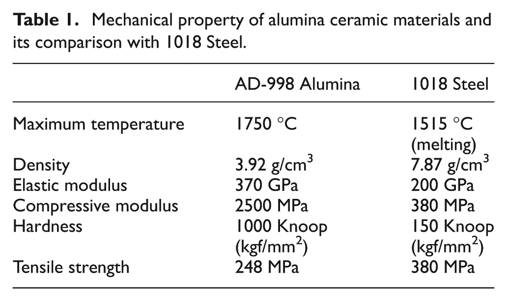
In general, an advanced ceramic material is created from the heating of power using the sintering processes. During sintering, atomic diffusion takes place. Microscopically, the sintering process is a result of both surface motion and grain boundary motion that minimizes the total sum of surface energy and grain boundary energy. Macroscopically, sintering is simply described as a densification, whereby the bulk density increases with a decrease in pore volume. After the sintering process, the hardness of the ceramic material increases drastically with a trade off in the ceramics’ ductility. The sintered alumina (Al2O3) ceramics studied in this research is a 99.8% alpha phase ceramics material manufactured by CoorsTek, Inc. Its mechanical properties are tabulated in Table 1. The atomic structure of alumina consists of planes of aluminum ions, interleaved with planes of oxygen maintaining charge neutrality of four
Mechanical property of alumina ceramic materials and its comparison with 1018 Steel.
Grain size and machining conditions determination
Clearly, it is impossible to use most conventional cutting tools to machine the aforementioned alumina ceramics, since it is much harder than the tool materials. Since diamond is the hardest material. The diamond-coated tools should have a good chance to machine the alumina ceramic materials if the machining conditions are well selected. Milling machining processes facilitate the material removal from a workpiece generally by chip formation. Chip formation occurs when a cutting tool imparts a force on the work material and causes a shear force along the slip plane in the atomic lattice; the dislocation of atomic lattice results in separation of materials; in this case, the material behaves in a ductile manner.20,21 Indentation on brittle materials shows that they can exert plastic deformations, while the depth of indentation is under some critical value. Plastic deformation of brittle materials can be obtained under the critical loads, if the brittle to ductile transition occurs. Many research results suggest that any material can be machined in a ductile manner as long as it is sufficiently scaled down to the grain size.22–24 It is necessary to obtain the knowledge of the grain size of the discussed alumina ceramics. The average size of grains is about 6 μm from the manufacturer of the alumina ceramics studied in this research. Since this piece of information is critical, it is verified as follows.
It is found that it is difficult to image the alpha phase of alumina ceramics, due to its high specularity as well as the inherent surface roughness on the outside surface. When imaging the alumina ceramic samples, they appear extremely bright and reflective under magnification. According to Richard Chinn’s research, 26 chemical etching can expose the grain boundaries of alumina ceramics material, so that during the imaging process, it is easier to discern the edges of the grain and the overall grain structure. Chemically, inert alumina is specifically known for its resistance to chemical attack, therefore an extreme environment is employed.
In this research, 85% phosphoric acid is first heated to its approximately 160 °C boiling point; then the alumina sample is immersed into the acid for 60–90 s to have the chemical etching take place, as shown in Figure 1. Once the etching operation is done, the sample is put into the boiling water to halt the chemical reaction. Then, the sample is taken out of the boiling water container and allowed to dry naturally. The etched sample is placed in a lapping machine for polishing before taking images. A 120-grit silicon carbide sand paper is used for grinding for about 30 min. The microstructure image was taken by an optical microscope (Olympus BX60M). It is found that the majority of grains have a size of larger than 6 μm. This knowledge is helpful when deciding the cutting parameters for experimental cutting tests. According to Shoichi Shimada’s research findings, 22 any material can be cut in a ductile manner as long as it is cut on the correct scale. It is postulated that if the alumina ceramic material was cut on a small enough scale, the fracture mechanism would change from a brittle fracture to a ductile fracture. Building directly from his research results, if it is possible to cut below the size of the grain, then the material will be more likely to slip along its slip planes as opposed to its fracture planes.26–28 So, it is desired to keep the feed below the grain size to realize the ductile regime machining for the alumina ceramic studied in this research.
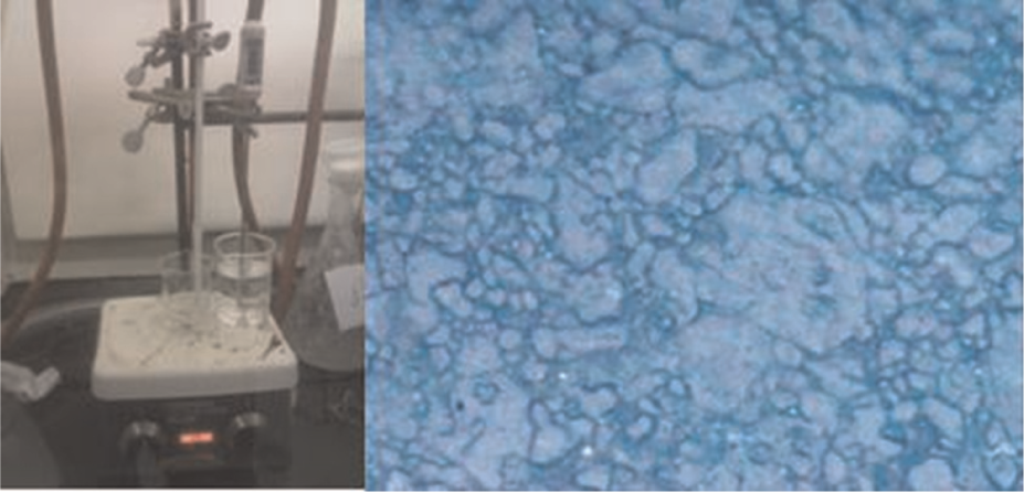
Alumina chemical etching process and etched surface’s microstructure image (1000×).
Experimental cutting tests
Cutting test setup and cutting tools
Milling cutting tests were conducted on a CNC vertical machining center (model VF-1) made by Haas Automation. The machine’s strokes are 508, 406, and 508 mm in the X, Y, and Z direction, respectively. Other technical specification features include a 40 taper tool holder, a 22.4-kW vector drive spindle with a maximum speed of 10,000 r/min, and a 20-station carousel tool changer. The feed drive’s rapid speed is 25.4 m/min. Its minimum motion resolution of 2 μm is particularly important for this research. Figure 2 shows the cutting experiment setup. The alumina ceramic samples made by CoorsTek, Inc., were cut into 6.35-mm-thick, 12.7-mm-wide, and 101.6-mm-long rectangular blocks. It is clamped by a high precision vise. The vise is mounted on top of a customized support plate; the plate is attached on top of the dynamometer for cutting force measurement. A Kistler piezoelectric force sensor (model 9367C) was used to measure the cutting forces in the X, Y, and Z directions. The assembly is mounted onto the machine’s table. There was no coolant applied for the experimental cutting tests. Note that the workpiece setting and the part zero locating need to be very precise and are very time-consuming.
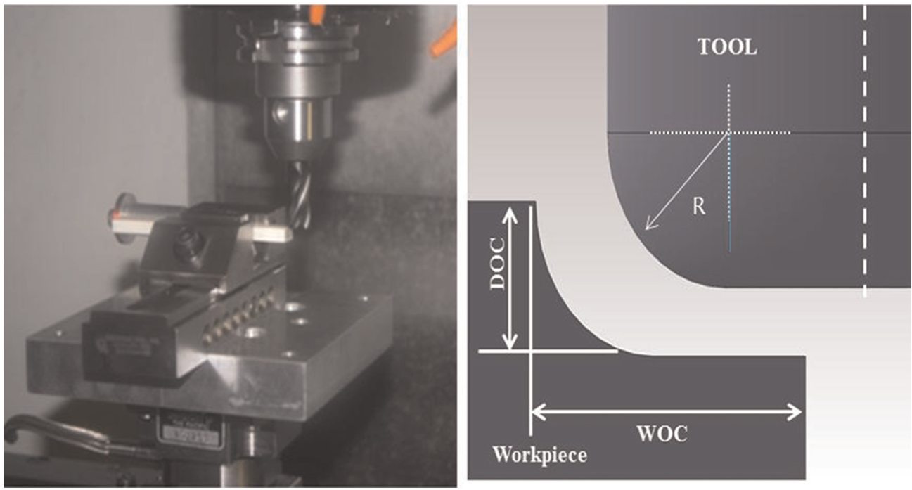
Cutting experiment setup and illustration of depth of cut (DOC) and width of cut (WOC).
In this research, the cutting tools are purchased from sp3 Inc. A total of four flutes of 12.7 mm diameter and CVD end mills of 6.35 mm diameter were used. Figure 3 shows the cutting tool images taken at different angles. The thickness of diamond coating is 10–15 μm. These tools have a primary angle of 10°, a secondary angle of 20°, a rake angle of 12°, and a helix of 30°. The corner radius (R) of the tool is 1.57 mm. WOC stands for width of cut; DOC stands for depth of cut as illustrated in Figure 2.
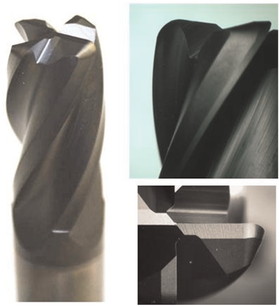
Cutting tool images (end view and side view).
Cutting test set I
Achievable MRR
There is no existing data that can be referenced to decide the cutting condition parameters. The primary guideline considered here is that the feed per revolution should be less than the average grain size of alumina ceramics, which is approximately 6 μm. The first set of cutting tests was done by using 6.35 mm diameter end mills from sp3 Inc. The cutting tool core’s material is tungsten carbide steel; the diamond coating is 10–15 μm thick. The tool’s corner is rounded to a radius of 1.57 mm. As illustrated in Figure 2, side milling operations are performed with a tool rotation speed of 6000 r/min, which corresponds to a linear cutting speed of 119.68 m/min. The DOC measured in the Z-axis direction is set to be 0.254 mm; the WOC varies from 0.25 to 3.81 mm as indicated in Table 2.
Cutting parameters versus surface roughness and material removal rate (MRR) (tool diameter: 6.35 mm, cutting speed: 119 m/min, and depth of cut (DOC): 0.254 mm).
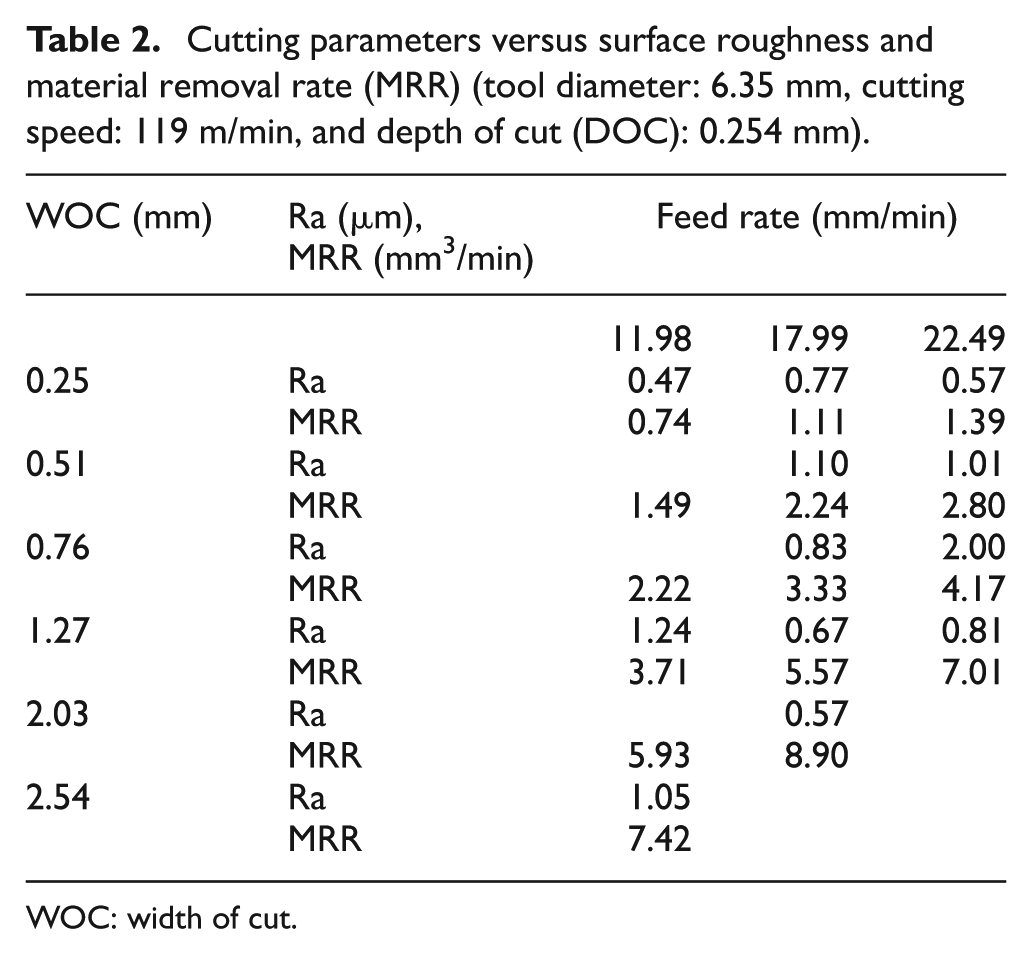
WOC: width of cut.
Table 2 also lists the measured surface roughness of machined surface and estimated MRRs with different machining conditions. The MRR is a composite parameter, which is calculated from all machining condition parameters. The MRR reflects the productivity of the machining process. The cutting length is set at 2000 mm length. The feed rates are 11.98, 17.99, and 22.49 mm/min, and the corresponding feeds are 2.00, 3.00, and 3.75 μm per revolution.
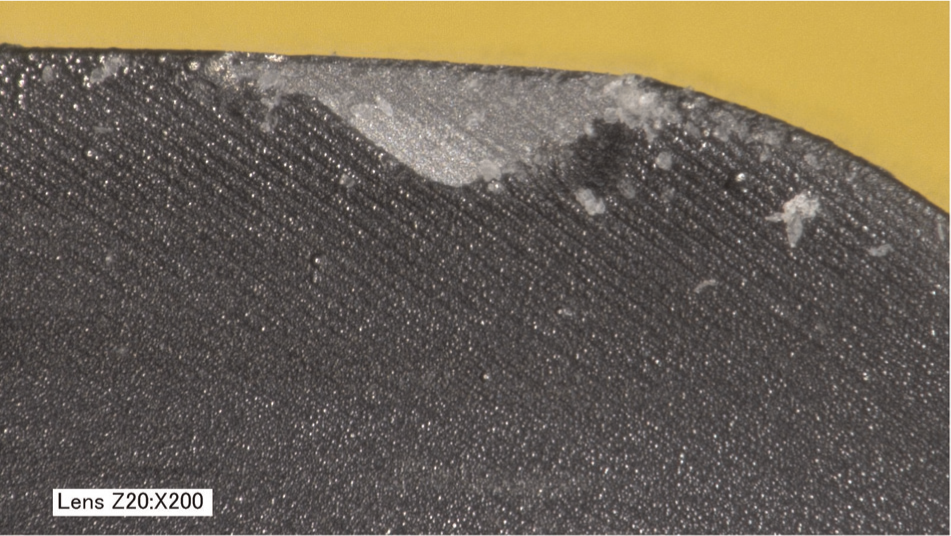
As seen from Table 2, a MRR of 7.42 mm3/min can be achieved under the condition of WOC 2.54 mm and a feed rate of 11.98 mm/min. When the WOC increases to 3.81 mm, it was noticed that abnormal cutting noise was heard when cutting starts and the cutting tool failed immediately. The cutting tests were also conducted at the feed rates of 17.99 and 22.49 mm/min, with maximum MRRs at 8.90 and 7.01 mm3/min. Figure 4(a) shows the machined surface with the machining condition of WOC 0.25 mm and a feed rate of 17.99 mm/min. The quality of the entire machined surface is very good and satisfactory. Figure 4(b) shows the machined surface with the machining condition of WOC 2.03 mm and a feed rate of 17.99 mm/min. The image is taken at the exit area of the machined surface. It is found that there are some “scratch” dark marks at the exit area, as shown in Figure 4(b). An abnormal noise was also observed at the end of the machining operation. Figure 4(c) shows the measured surface at the machining condition of WOC 2.54 mm and the feed rate of 17.99 mm/min. It is found that there is no alumina ceramic materials removed under this set of machining conditions; the tool failed catastrophically. The surface area that the tool contacted has a metallic dark color, which means that the diamond coating is gone; the substrate core is exposed. The core (base) material rubs the alumina ceramic without removing the material. Figure 5 shows an obtained scanning electron microscope (SEM) image of a worn tool from the cutting test. Apparently, the diamond coating was partially delaminated and peeled off.
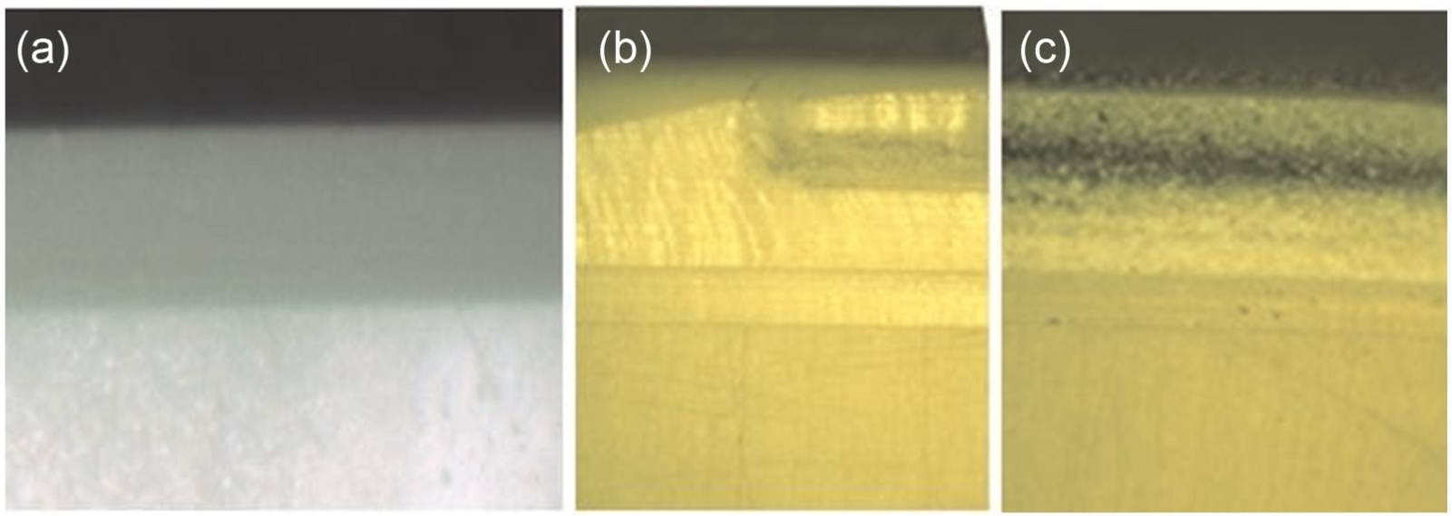
Machined alumina ceramics surface under different cutting conditions.
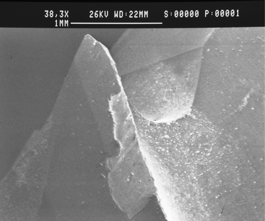
SEM image of worn tool tip area.
Based on the experimental cutting tests, it is found that it is also true for the alumina ceramic material machining with CVD diamond-coated tools, that the cutting tool wear and tool life are directly associated with the MRRs. The MRR is associated with cutting forces exerted on the tools, which affects the tool life. The machining conditions must be well selected in order to maintain the reasonable tool life. A 7 mm3/min MRR can be obtained from this set of cutting tests. It is concluded that the alumina ceramic material is “cuttable” by using CVD diamond coating tools and that a reasonable MRR can be achieved.
Machined surface roughness analysis
The machined surface roughness is measured using a stylus contact surface profilometer made by Mitutoyo Corporation for the machined alumina ceramic surfaces. The surface roughness is represented by the parameter Ra. Ra is the arithmetic average of the absolute values of sampling point heights. The measurement cutoff length is 0.8 mm; the sampling interval is 8.68 μm; and a number of 9216 data are acquired for each measurement. The roughness value shown in Table 2 is the average value obtained from three locations of the machined surface for each cutting test. Figure 6 illustrates an example of part of the measured surface profile, which is different from both a typical milled surface profile and a ground surface profile for metallic materials.
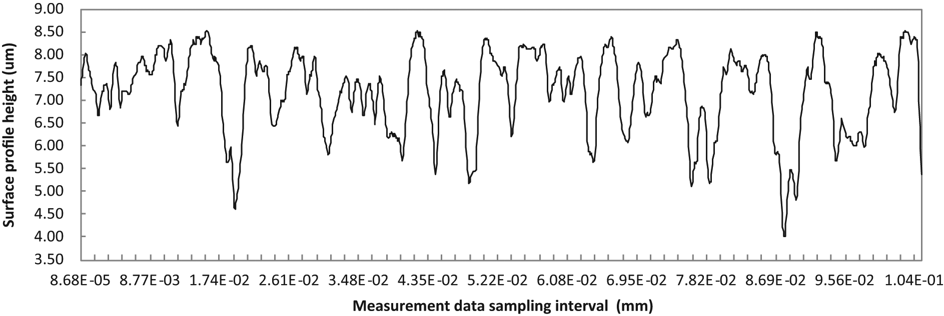
Measured surface profile for surface roughness parameter (Ra) estimation.
A obtained from Table 2, the surface roughness values are 0.47, 0.77, and 0.57 μm, respectively, under the different feed rates of 11.98, 17.99, and 22.49 mm/min. This fact shows the surface roughness does not increase with the increase in the feed rates. It is known that a large feed rate will result in a large surface roughness for a conventional cutting process. Therefore, the material removal mechanism of studied ceramic milling process differs from a traditional material removal mechanism. It is also found that the surface roughness is of a larger value when the MRR is about 4 mm3/min.
Figure 7 shows an image of a cutting edge surface obtained by using a three-dimensional (3D) digital microscope (Keyence VHX2000), which is capable of 3D surface analysis. It is clear that the surface of the tool’s core prior to coating is not a “smooth” or “flat” surface. It has a texture with micro grooves oriented in a certain direction. This texture is normally used to enhance the adhesion strength between the diamond coating and the substrate to prevent diamond coating delamination during the machining. This inherent surface micro texture has more influence on the machined surface. So, if the thickness of the deposit diamond coating around the cutting edge area is less than the depth of the substrate micro groove, the substrate texture will influence the machined surface finish. It is also found that there is a light area in the tool wear image as shown in Figure 7. The diamond coating located in this area was chipped away deliberately. The surface roughness Ra is less than 1.56 μm for all machined surfaces. If a better surface finish is required, the thickness of the coated layer must be larger than the depth of the micro groove on the tool’s core.
Diamond-coated tool surface texture image.
Cutting test set II
More cutting tests have been done by using 12.7 mm diameter tools. The tool’s geometric shape, tool’s core material, and coating, are the same as the tools discussed in “Cutting test set I” section. The machining conditions and obtained results are listed in Tables 3 and 4.
Cutting parameters versus surface roughness and material removal rate (MRR) (tool diameter: 12.70 mm, cutting speed: 119 m/min, and depth of cut (DOC): 0.254 mm).
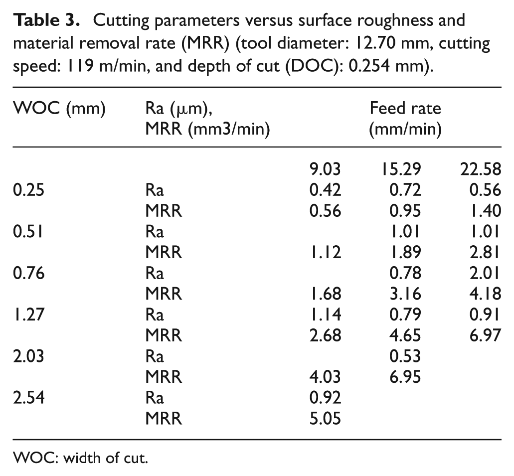
WOC: width of cut.
Cutting parameters versus surface roughness and material removal rate (MRR) (tool diameter: 12.70 mm, cutting speed: 159 m/min, and depth of cut (DOC): 0.254 mm)
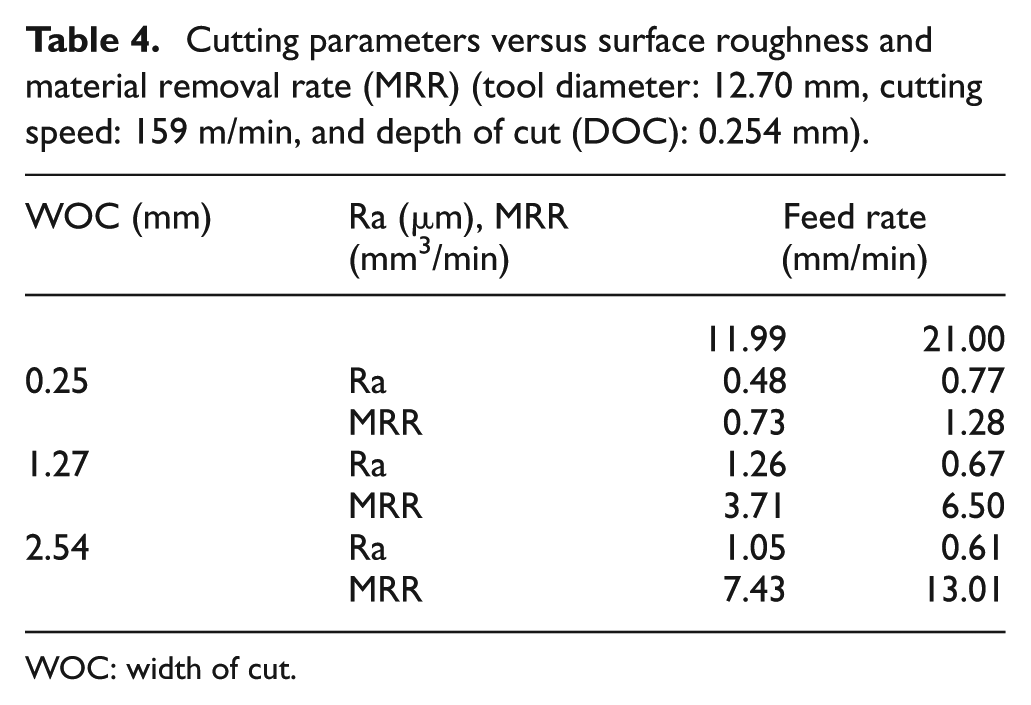
WOC: width of cut.
For the tests listed in Table 3, the spindle’s rotational speed is 3000 r/min and the cutting speed is 119.01 m/min; for the tests listed in Table 4, the spindle’s rotational speed is 4000 r/min and the cutting speed is 159.51 m/min. The measured surface roughness results listed in Tables 3 and 4 show that the machined surface is relatively rough when the MRR is about 4 mm3/min. These results are also consistent with the results listed in Table 2. It is noticed that the surface roughness at a relatively large MRR of 8.99 mm3/min is about the same as the surface roughness at a relatively small MRR of 1.39 mm3/min. It is found that a MRR of approximately 5 mm3/min can be achieved in the case of a spindle speed of 3000 r/min. In a case with a cutting speed of 4000 r/min, the maximum MRR is 7.435 mm3/min when the feed rate is 11.99 mm/min. When the feed rate increases to 21.00 mm/min, the MRR is 13.01 mm3/min. However, it was observed that the tool’s vibration dramatically increases at the end of the machining process. Figure 8 shows the tool wear area size measured after the machining. When machining at a condition of WOC 2.54 mm and a feed rate of 11.9 mm/min, the wear area size on the flank face was 0.00645 mm2 as illustrated in Figure 8(a); when the feed rate increased to 21.00 mm/min, the tool wear area size increased to 0.0323 mm2. The cutting tool suffers a severe damage at the feed rate of 21.00 mm/min, which deteriorates the machined surface finish and leads the tool to the end of its life. It is not recommended to conduct the machining processes under this set of cutting parameters. Based on results obtained in Tables 3 and 4, a conclusion can be drawn that the MRR should be limited to 5–6 mm3/min in order to conduct a normal machining process with a reasonable tool life.
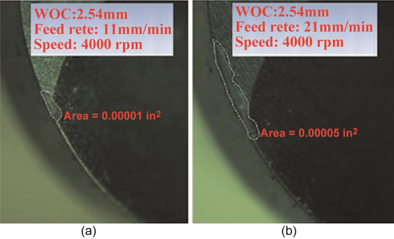
Tool wear area size measurement results.
Cutting force analysis
Cutting forces were measured by using Kistler piezoelectric force sensors (model 9257C; Kistler Group) for all cutting tests. The sensor setup is addressed in the previous section as shown in Figure 2. Figure 9 shows the measured forces under the machining conditions of the feed rate 11.9 mm/min, the spindle rotational speed at 3000 r/min, and the DOC 0.254 mm (0.01 in). Figure 9(a) shows the cutting forces Fx, Fy, and Fz measured in three directions at the WOC 0.254 mm. It is found that the cutting force’s variation is stable. The cutting force Fy is less than 5 N. Figure 9(b) shows the measured cutting forces at the machining conditions of the WOC 2.54 mm. It can be found that the cutting forces become much larger, and their peak’s variation is unstable as the cutting time progresses. An unstable fluctuation of cutting force is indicative of impending tool life. Figure 9(c) is the measured cutting forces at the conditions of WOC 3.81 mm. It is observed that a high pitch abnormal noise was generated when the cutting starts, which indicates that the tool failed immediately. Figure 10(a) is the image of the cutting edge of a brand new tool. The damaged tool was imaged as shown in Figure 10(b). The tool’s tip is chipped away due to the excessive impact cutting force when the tool edge first engages with the workpiece. So, it is impossible to carry out a normal machining operation under this set of machining conditions. The average cutting forces are estimated as shown in Figure 11. The average forces in the X, Y, and Z direction are approximately 1.5, 3.3, and 17 N, respectively, at the WOC of 0.254 mm and the cutting speed of 3000 r/min. These forces that are applied are direct results of the amount of material removed.
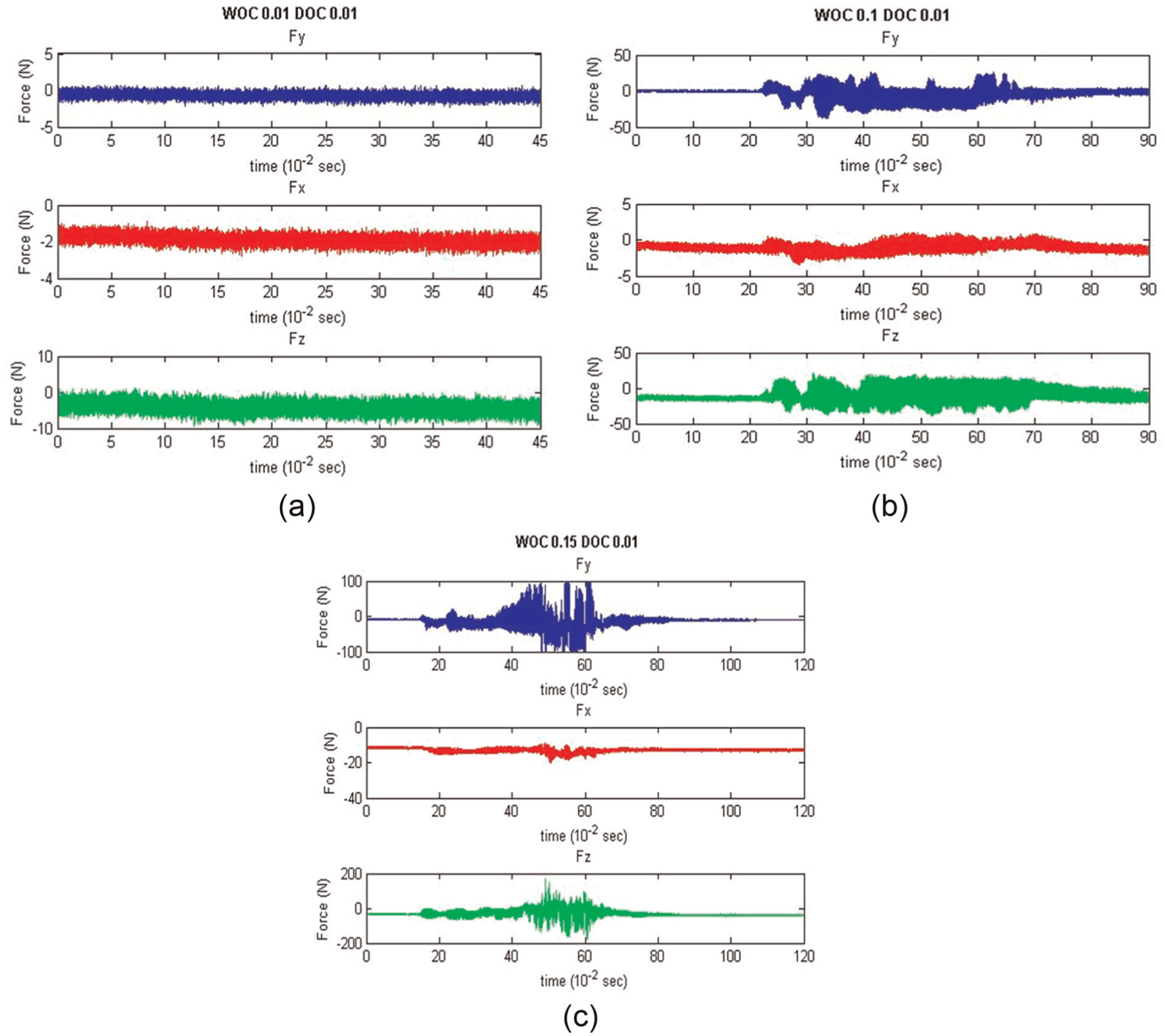
Measured cutting forces in X, Y, and Z directions at different width of cut (WOC): (a) 0.254 mm, (b) 2.54 mm, and (c) 3.81 mm.
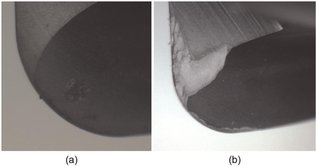
(a) New tool tip and (b) chipped tool tip.
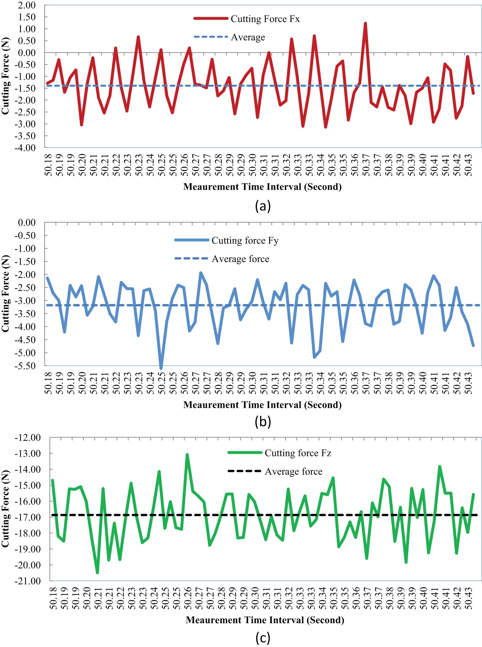
Average values of cutting forces in X, Y, and Z directions: (a) Fx, (b) Fy, and (c) Fz.
Figures 12 and 13 show the peak values of the cutting forces in the Y direction, and the MRRs with different WOC and the cutting speeds of 119 and 159 m/min, respectively. Clearly, the cutting force’s variation is correlated with the MRR. A larger MRR corresponds to a larger cutting force measured in the Y direction. From both figures, when the cutting forces in the Y direction reach approximately 100 N, the tool fails. It is observed that when a rapid and sudden undulation in the force graphs occurs, the tool failure occurs. These results are meaningful when deciding the machining conditions for alumina ceramic materials using CVD diamond coating tools.
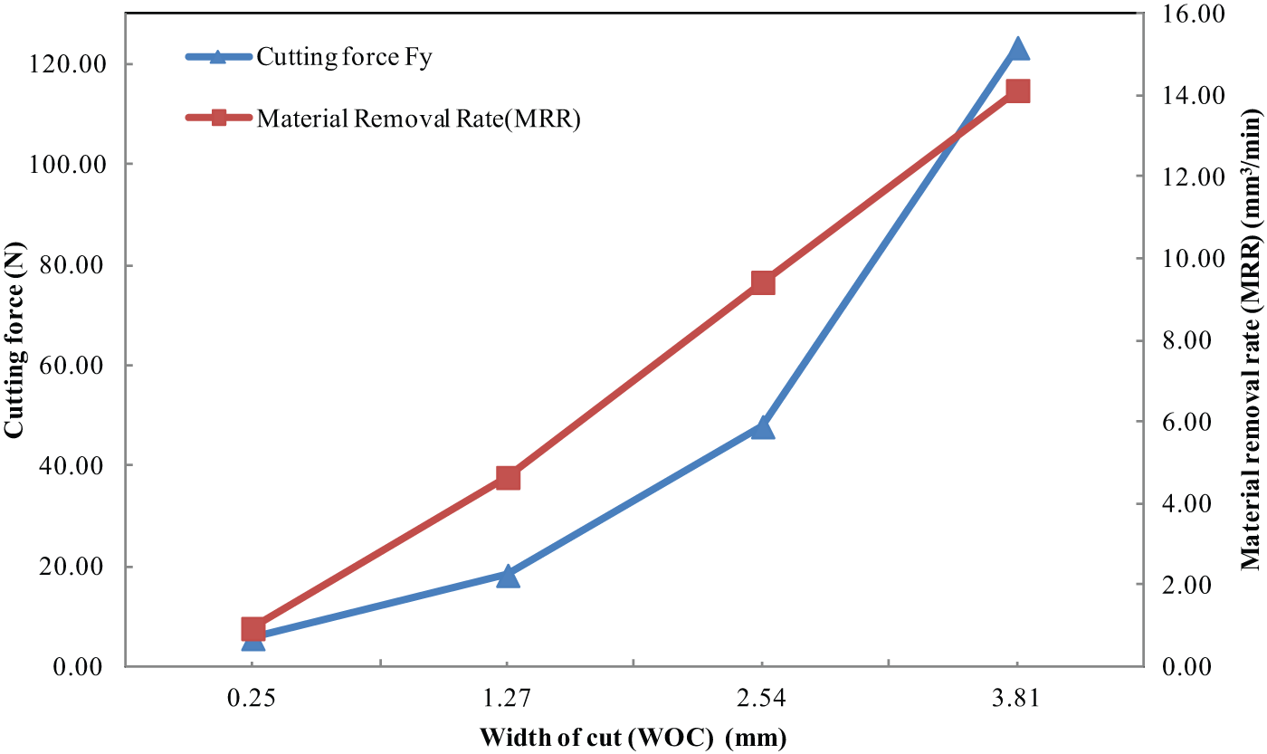
Cutting forces in Y direction versus different width of cut (cutting speed: 119 m/min).
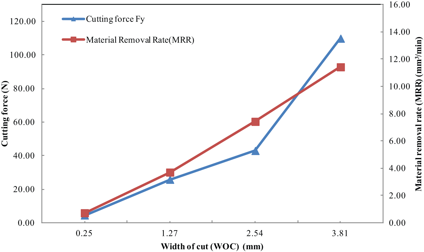
Cutting forces in Y direction versus different width of cut (cutting speed: 159 m/min).
In this research, two alumina parts shown in Figure 14 are designed and fabricated to verify the obtained results. Based on the obtained experimental results, the cutting parameters for machining these two parts were determined as follows: cutting speed of 3000 r/min, tool diameter of 12.7 mm, DOC of 2.54 mm, and WOC of 0.254 mm. In Figure 14, the parts with white color are machined alumina ceramic parts. Note that the parts with dark color are aluminum parts, which is used to display the details of the part, since the alumina part’s images are not easily viewable. The cutting process was successfully conducted without changing the tool.
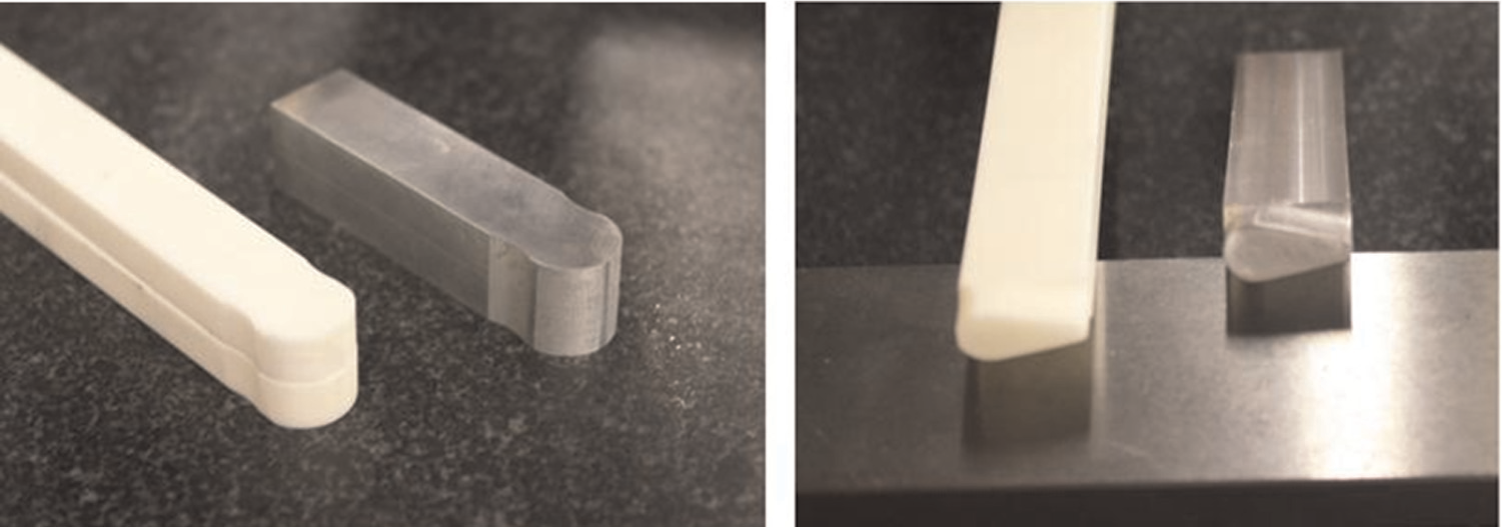
Machined alumina ceramics parts (white color) based on the research results.
Conclusion
In order to investigate the machinability of alumina (Al2O3) ceramic materials, machining tests with CVD diamond coating milling tools were conducted under various machining conditions on a common 3-axis CNC milling center in this research. The findings from experimental tests are summarized as follows:
Alumina (Al2O3) ceramic is “cuttable” with CVD diamond coating tools as long as a set of appropriate machining conditions can be chosen.
The machining outcome largely depends on the cutting conditions, including the cutting speed, the feed rates, and the WOC. A MRR of 5–6 mm3/min is achievable, which is significant.
The diamond coating on the surface of the tool is volatile and tends to crack, and chip once the MRR reaches a threshold value.
The machined surface finish is influenced by the substrates’ micro texture, if the diamond coating is not thick enough to cover the inherent texture.
A sudden undulation in the cutting force variation is indicative of tool failure; the tool wear status can also be monitored by observing the machined surface’s color.
Footnotes
Acknowledgements
The authors are grateful to all study participants for their contributions and to Adrian Avila and Brian Weick for their great technical support.
Declaration of conflicting interests
The authors declare that there is no conflict of interest.
Funding
This research received no specific grant from any funding agency in the public, commercial, or not-for-profit sectors.