
Abstract
Electrodes made of graphite material are widely used for electro discharge machining. The performance of physical vapor deposition AlTiN and chemical vapor deposition diamond-coated carbide end-milling tools in dry high-speed milling of electro discharge machining graphite was investigated, also adopting an uncoated one as a comparison. The quality of as-deposited diamond film was evaluated by Raman spectroscopy. The adhesion between the coating and the substrate was assessed by indentation test. The tool life and wear mechanism of the milling tools, the cutting forces during tests, as well as the roughness of processed surfaces were systematically studied. It is found that the diamond coating has lower adhesion than the AlTiN coating under the same load. Coating delamination and chipping, irregularly zigzag side flank wear, concave structure on the cutting edge are primary wear patterns for the diamond-coated tool. While different primary wear patterns, including uniform polishing abrasive flank wear and crater rake wear, are observed on the AlTiN-coated tool. Besides, the total cutting force of the diamond-coated tool is larger than that of the AlTiN-coated tool when the diamond-coated tool side flank wear value reaches 0.06 mm, attributed to the different wear patterns. Another notable result is clarified that the chipping of the diamond coating can cause significant increment in the feed force, radial force and worked surface roughness.
Keywords
Introduction
The homogeneous graphite electrode, owing to its lower wear, quicker electro discharge machining (EDM) speed, higher heat resistance and better machining precision compared with the copper electrode, has been gradually substituted for the latter in EDM applications. It is believed that the machining mechanism of the graphite is different from that of the metal. The graphite structure undergoes localized fractures rather than plastic deformation and chip formation during machining. 1 For graphite, high-speed machining is the dominant machining method. A mass of small fragments and chips will accumulate on flank and rake surfaces of cutting tools together with workpiece surfaces when high-speed machining graphite. Consequently, cutting tools will suffer friction and impact effects caused by the workpiece and chips, while workpiece surfaces will suffer impact and crush effects, which results in uneven processed surface and a shortened tool life for tools without coating. Moreover, the EDM graphite is used in mold industry. The machining EDM graphite should be clearly divided into roughing and finishing stages of processing to ensure accuracy. The cutting tool should have longer lifetime and little tool wear to meet the request of machining EDM graphite. Furthermore, higher processing efficiency and lower manufacturing cost are the goal of manufacturing industry. Therefore, cutting tool with excellent performance and well-processed surface quality is the goal for researchers and manufacturing firms to pursue when high-speed milling of EDM graphite.
TiAlN-based coating with higher hardness and excellent oxidation resistance is widely applied in cutting tool for metal machining.2,3 The TiAlN-coated tool adopted for milling industrial graphite electrodes was studied by Schroeter et al. 4 The cutting length was only 12–16 m until flank wear value reached 0.1 mm at 200 and 400 m/min. The chemical vapor deposition (CVD) diamond-coated tool has the most extreme properties such as excellent tribological properties and superior wear resistance, which has been applied for machining Al2O3 ceramics material, carbon fiber–reinforced plastics (CFRP), Al alloy and monocrystalline silicon.5–9 The CVD diamond-coated tool also has distinct advantage over other coated tool during machining graphite. It is found that the tool life of the diamond-coated driller was six times of the TiAlN-coated one when micro-drilling of the graphite. 10 Kanda et al. 11 reported that CVD diamond-coated cemented carbide tools had 10 times tool life than uncoated ones in milling of graphite. According to some statistics, the manufacturing cost will decrease 15% when the cutting efficiency improves 20%. The cost of the cutting tool is only 2%–4% of manufacturing cost. However, the performance of cutting tool directly determines the cutting speed and feed. Besides, replacing and re-installing cutting tool will expand 10%–15% of effective processing time. CVD diamond-coated tool could work under higher cutting speed and longer lifetime compared with AlTiN-coated tool. The manufacturing cost will be decreased although the cost of CVD diamond-coated tool is times over than that of AlTiN-coated tool. Thus, the development of diamond-coated tool with excellent performances is not only science research but also an economic goal.
Micro- and nano-crystalline CVD diamond coatings were deposited on Si3N4 ceramic tools. 12 Both of Micro- and nano-crystalline CVD diamond-coated tools have similar cutting force (<20 N) in the turning of the EDM graphite. The smoother nano-crystalline coating allowed for obtaining a better workpiece surface roughness than the microcrystalline one. In one another research, the SiC film was deposited on the WC-6% Co cemented carbide as interlayer for diamond-coated insert to further extend the tool life. 13 The dry turning graphite test showed that multilayer (SiC + diamond) coatings exhibited the longest tool life, compared with commercially sintered diamond (polycrystalline diamond (PCD)) inserts and diamond-coated inserts with no interlayer. Cabral et al. 1 developed time-modulated chemical vapor deposition (TMCVD) process. The turning graphite tests showed that the TMCVD diamond-coated inserts exhibit a better wear resistance with respect to inserts coated with conventional diamond coating, PCD and bare WC–Co inserts.
The wear mechanism of AlTiN-coated tool in high-speed milling of graphite was studied by Zhou et al. 14 The result showed that coating delamination and edge micro-chipping occurred in the initial stage, and then, worn areas increased almost linearly with tool displacement in the steady wear stage; the flank wear was the dominant wear pattern, and abrasive and erosion wear mechanisms functioned in the steady wear stage. Flank wear, crater wear and nothing are the main wear modes for flat diamond coated inserts in turning of graphite.1,15 Lei et al. 10 found that the main wear types of AlTiN- and diamond-coated microdrills were flank wear, chipping and coating delamination.
Above research results showed that the failure mechanism primarily originated from the coating delamination and micro-chipping for AlTiN-coated tools in milling of graphite while flank and crater wear, chipping and coating delamination for diamond-coated tools in turning and drilling of graphite. Nevertheless, the wear mechanism of the diamond-coated tool in high-speed milling of graphite needs further study. The changes in the cutting force and the worked workpiece surface roughness after spalling of diamond coaitng for diamond coated tool have not been studied. In this study, AlTiN and diamond coating were deposited on WC–Co solid carbide tools by the cathodic arc evaporation and hot filament chemical vapor deposition (HFCVD), respectively. Variations in the tool life, wear mechanism, cutting force and roughness of processed graphite on the coating spalling and tool wear were investigated for AlTiN-coated, diamond-coated and uncoated WC tools.
Experimental procedures
WC-6% Co solid carbide cutters (D6*24*60) were used as substrates for depositing different films and subsequent milling tests. WC-6% Co solid carbide bars (D6*60) with two parallel surfaces were utilized to deposit coatings for measuring mechanical properties. The AlTiN coating was deposited by a commercial cathodic arc coating machine. N2 gas pressure, substrate temperature and substrate bias were kept at 1.8 Pa, 723–772 K and −80 V, respectively. Diamond coating was deposited by the conventional HFCVD technique. Pretreatments were done before diamond coating deposition. The substrates were chemical etched for 5 min in Murakami solution (10 g K3 (Fe (CN)6) + 10 g KOH + 100 mL H2O) with ultrasonic wave field and then etched for 15 min in HNO3:HCl:H2O = 1:1:10 in an ultrasonic bath to wash surface cobalt out. During the deposition process of the diamond film, the working pressure, carbon–hydrogen ratio and filament temperature were kept at 300 mbar, 1 vol.% and 2273–2573 K, respectively. The coating thickness of the AlTiN and diamond coating on the tool side flank face was 2–3 and 6–8 µm, respectively. The adhesive strength of AlTiN and diamond coating with the substrate was assessed by the Rockwell A indentation test (HRA) with loadings at 588 N. The hardness of AlTiN coating was measured by CSM nano-hardness tester. Diamond coating was characterized by micro-Raman measurements (equipped with a 632 nm He-Ne laser). The as-deposited coating morphology and the worn tools were studied by scanning electron microscope (SEM)/energy dispersive spectroscopy (EDS).
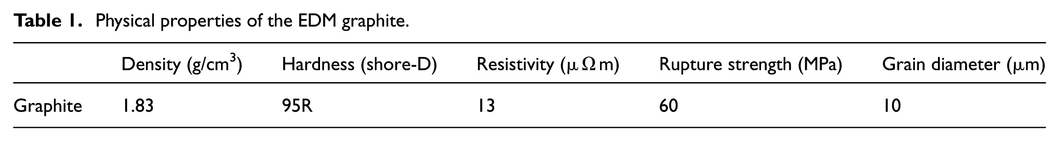
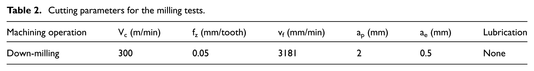
During the cutting tests, different tool specimens are employed for end-milling the EDM graphite, without lubrication. Physical properties of adopted EDM graphite are shown in Table 1. Cutting parameters, determined according to the industrial processing technology, are presented in Table 2. Two to three rounds of cutting tests were carried out to ensure the repeatability of the results. Tool wear measurements were carried out at each regular machined length. The tool-life tests, according to the Norm ISO 8688-2, were related to end-milling, where the tool edge is predominantly used. The choice of “end-life” criteria for the analyses was the width of the side flank wear land VB = 0.1 mm according to the necessities of this study. The flank wear of the coated tool was measured as illustrated in Figure 1(b) by a digital microscope VHX-600. Cutting forces were measured with a Kistler three-component dynamometer, a multi-channel charge amplifier and a computer data acquisition system. The surface roughness of machined graphite was tested by SJ301 surface roughometer. The flow diagram of the experimental procedures and the main experimental setup and materials are shown in Figure 2.
Physical properties of the EDM graphite.
Cutting parameters for the milling tests.
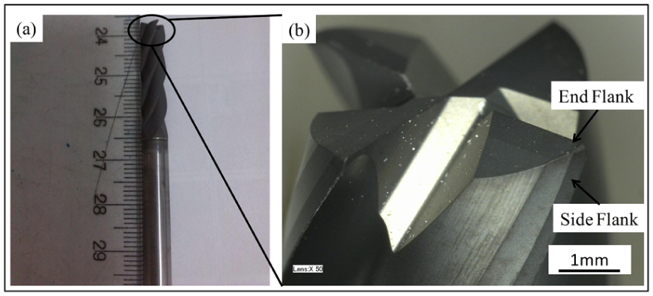
(a) The test tool and (b) tool wear measured areas.
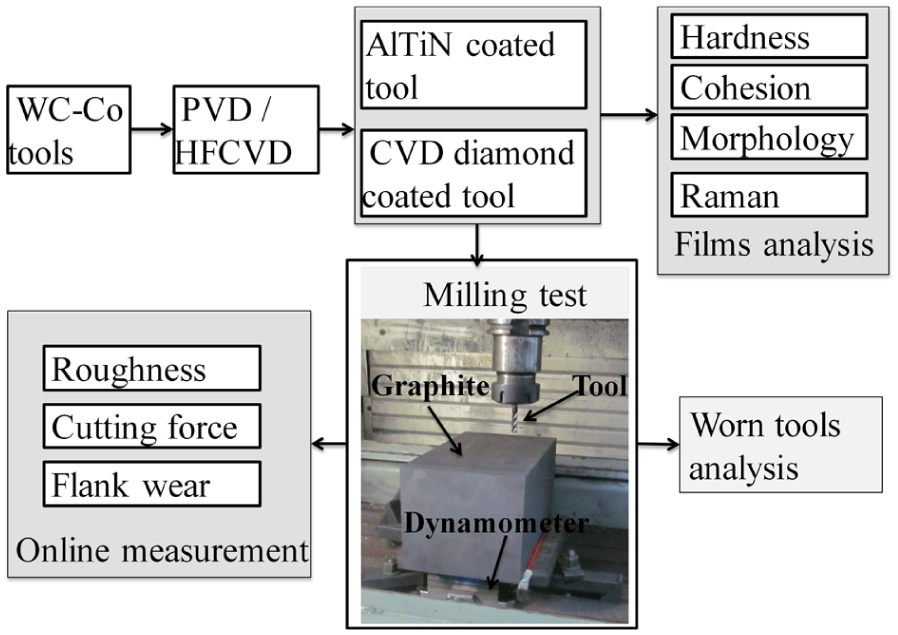
The flow diagram of experimental procedures and main experimental setup and materials.
Results and discussion
Film characterization
Figure 3 shows surface morphologies of the AlTiN and diamond coatings deposited on the tool side flank face. Macro-particles with different sizes are observable on the surface of the AlTiN coating. The largest diameter of the macro-particles is about 2 µm. The relative composition of AlTiN coating was determined by EDS. Al/Ti atomic ratio is approximately 0.66:0.34. The diamond coating is a microcrystalline structure and the largest grain size is about 2–3 µm. Many nano-crystals also exist on grain boundaries between micro-crystals. The hardness and elastic modulus of AlTiN coating are 27.22 ± 2 and 346.97 ± 30 GPa, respectively. The hardness and elastic modulus of diamond coating were estimated by other studies, demonstrating that the hardness of microcrystalline and nano-crystalline/micro-crystalline composited diamond coatings was in the range of 72–129 and 84–110 GPa, respectively. 16 The hardness and elastic modulus values of the diamond coating with 1–2 µm grains were about 105 and 1147 GPa, respectively. 17 Some other hardness (121 ± 25 GPa) and elastic modulus (1036 ± 163 GPa) were achieved on nano-crystalline diamond coating with a deposition temperature of 926 K. 15 In consequence, it is supposed that the hardness and elastic modulus of the diamond coating in this work should be in the range of 70–129 and 870–1200 GPa, respectively.
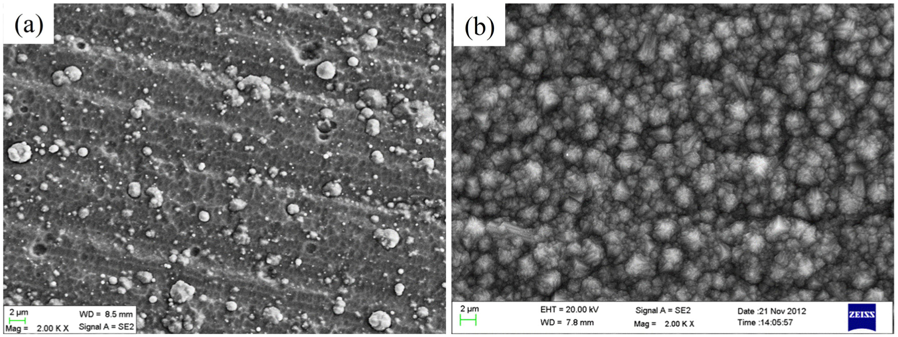
The as-deposited morphology of (a) AlTiN and (b) diamond coating on the tool side flank.
The adhesive strength between the substrate and the coating is an important factor characterizing the quality of the coating. The indentation morphologies of coated cemented carbides under a load of 588 N are presented in Figure 4. The load applied on the diamond-coated cemented carbide causes crack propagation and delamination at the edge of the indentation contact region as shown in Figure 4(b). Meanwhile, only severe micro-cracks are observed around the imprint of the AlTiN-coated cemented carbide. The results demonstrate that cracks and delamination are easier to form for the CVD diamond-coated cemented carbide than for the AlTiN-coated cemented carbide, indicating that the CVD diamond coating has lower adhesion with the substrate than the AlTiN coating.
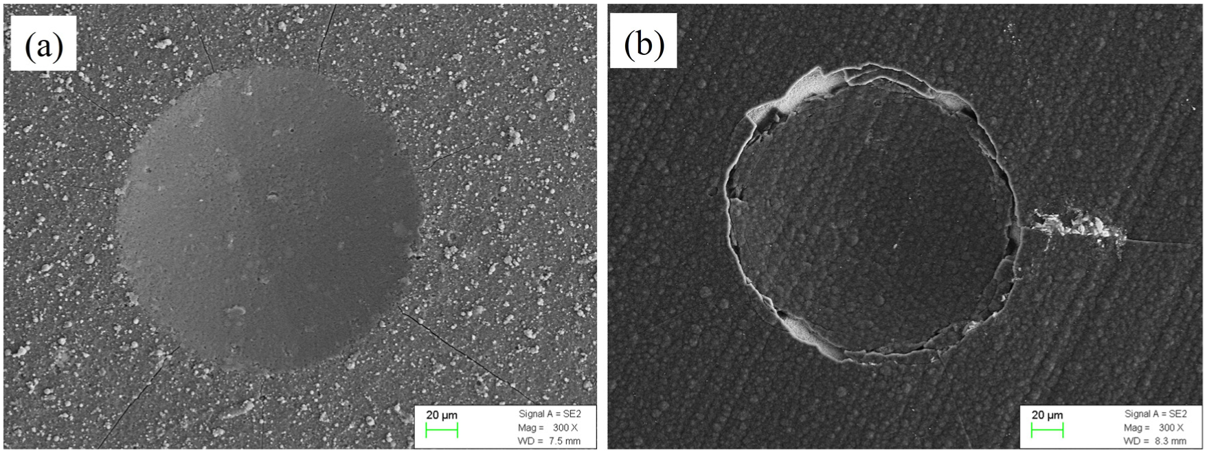
Indentation morphology of (a) AlTiN- and (b) diamond-coated cemented carbides with loadings at 588 N.
H3/E*2 is proportional to the resistance to the plastic deformation. 18 E* = E/(1 − v2), where E is the elastic modulus and v is the Poisson ratio (0.25). 19 Higher H3/E*2 value of coating suggests that it has better wear resistance and stronger capability of resistance to plastic deformation. H3/E*2 value of the diamond coating is in the range of 0.57–1.31. However, that of the AlTiN coating is only 0.15. The results indicate that the diamond coating has better wear resistance and worse plastic deformation ability.
Micro-Raman spectroscopy is employed to assess the quality of the diamond coating, as shown in Figure 5. In addition to the characteristic first-order diamond Raman band, the typical sharp peak at about 1336 cm−1, the spectrum also displays extra features centered around 1139, 1366, 1490 and 1551 cm−1. It is recognized that disordered graphite corresponds to two fairly sharp modes in the Raman spectrum: G band centered around 1580 cm−1 and D band centered around 1350 cm−1. Peaks centered at ∼1551 and ∼1366 cm−1 are attributed to the corresponding graphite bands. The origin of peaks at ∼1140 and ∼1470 cm−1 has no uniform viewpoint so far. The ∼1140 cm−1 Raman feature is often invoked as a signifier of a nano-crystalline diamond phase in grown CVD samples.20,21 Ferrari and Robertson 22 pointed that the peaks at ∼1140 and ∼1470 cm−1 were expected for sp2 bonded configurations, which were assigned to transpolyacetylene segments at grain boundaries and surface. Wei et al. 23 established the A1355/A1575 and A1140/A1470 pair correlations, comparing with the relative areas of one feature from each pair in each of the Raman spectra. He deemed the ∼1140 and ∼1470 cm−1 features to sp2 carbon base structures. In this work, the peak at ∼1139 cm−1 may be nano-crystalline diamond phase (as shown in Figure 3) and the peak at ∼1490 cm−1 may not be diamond phase, regarded as amorphous or sp2 carbon base structures.
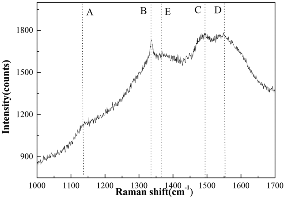
Raman spectra of diamond coating.
Tool life and tool wear
In Figures 6 and 7, side flank wear and end flank wear of coated and uncoated tools in high-speed milling of graphite are shown. The AlTiN coating improves 30%–40% tool lifetime when side flank wear value reaches to 0.1 mm compared with the uncoated tool. The diamond coating increases the tool lifetime nearly 10 times compared with the AlTiN coating. Delamination and chipping break out when the cutting length is at 450–600 m for the diamond-coated tool. Triangular wear area was present on the end flank face for all the tools. AlTiN-coated tool shows the same end flank wear value as uncoated tool.
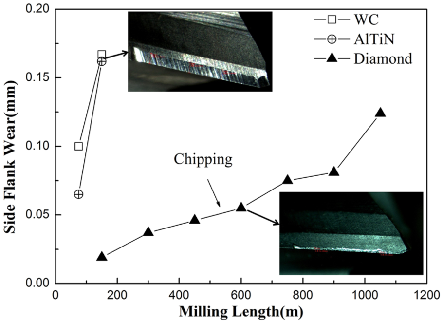
Graphical representation of the side flank wears versus the milling length.
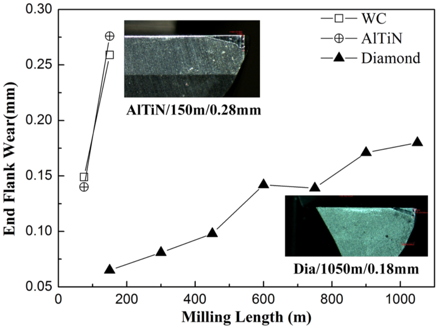
Graphical representation of the end flank wears versus the milling length.
Figure 8 shows worn morphologies of the AlTiN-coated tool after high-speed milling of graphite. Flank and crater wear are the principal wear patterns. Furrows and smooth surface on the cutting edge and flank face of the worn tool, respectively, are shown in Figure 8(a). They are the forms of “Micro-cutting” and “polishing” abrasive wear in the high-speed milling of graphite. 14 “Micro-cutting” and “polishing” abrasive wear appear on the impact zone and slippage zone, which are formed on the cutting edge and flank face of the tools during cutting of graphite. 24 The cutting tool suffers high impact and compressive stresses in the impact zone. At the same time, the relative slippage action of graphite chips superimposes a small compression on the tool surfaces in the slippage zone. Therefore, furrows and smooth surface are on the impact and slippage zones, respectively. A smooth and uniform grinding trace was noticed on the side and end flank face after milling test, as shown in Figures 6–8. That results from the “polishing” abrasive wear. Schroeter et al. 4 found the same wear phenomenon and classified it as “uniform flank deterioration phenomenon.” The chemical composition of areas 1, 2, 3 and 4 in Figure 8(b) is analyzed by EDS. The detailed data are given in Table 3. The results show that graphite is only in the vicinity of the wear land and no graphite is on the wear land. The similar element distribution was on the end flank wear area. It can be concluded that the graphitic carbon does not diffuse into the tool. Therefore, diffusion and adhesive wear may have little influence on tool wear and abrasive wear is the main wear mechanism for AlTiN-coated tool on the wear land.
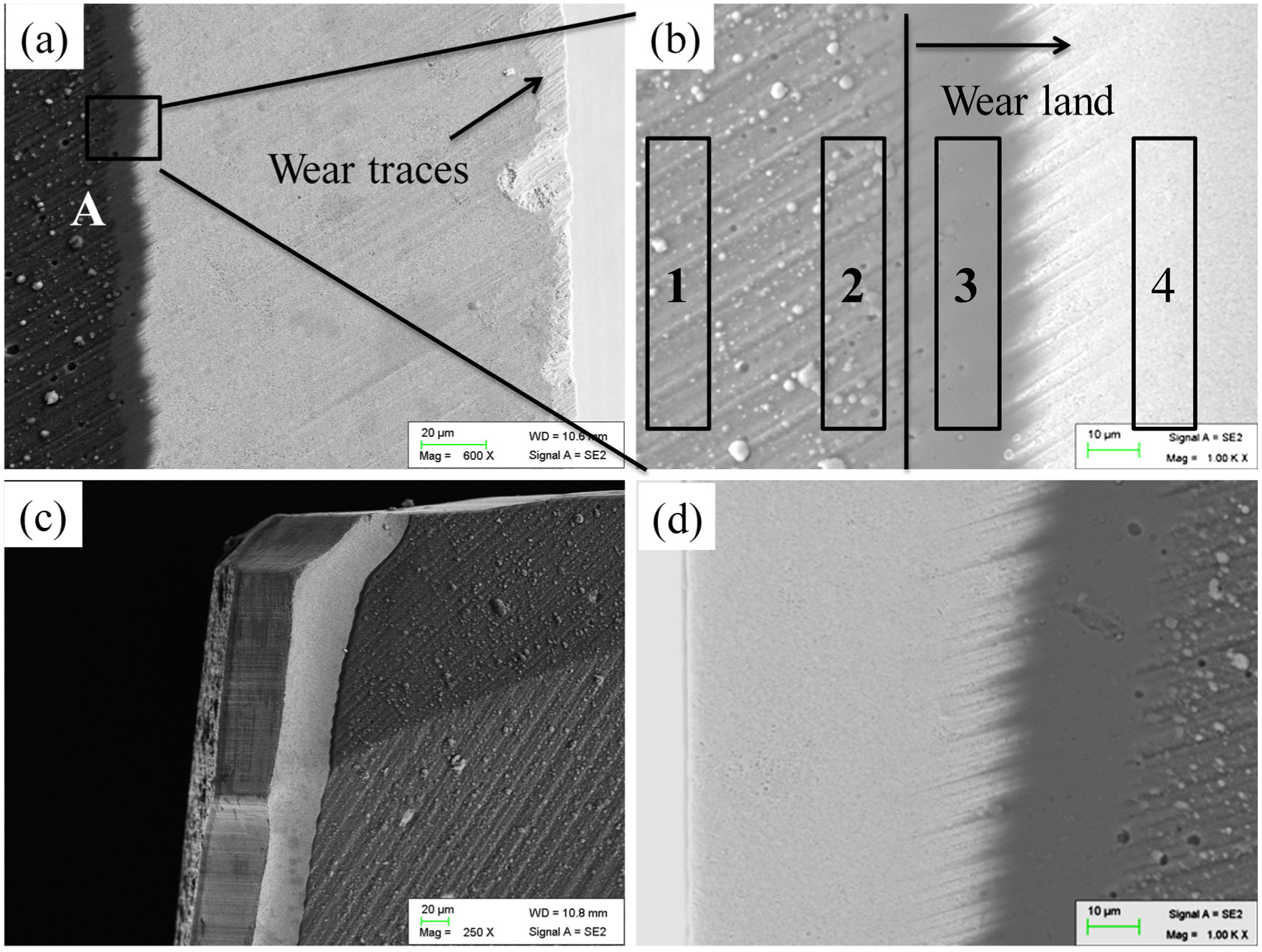
Worn morphology of AlTiN-coated tool after milling graphite for 150 m: (a) side flank, (b) enlargement of region A in (a), (c) rake and (d) end flank.
The chemical composition of areas 1, 2, 3 and 4 in Figure 7(b) (wt%).
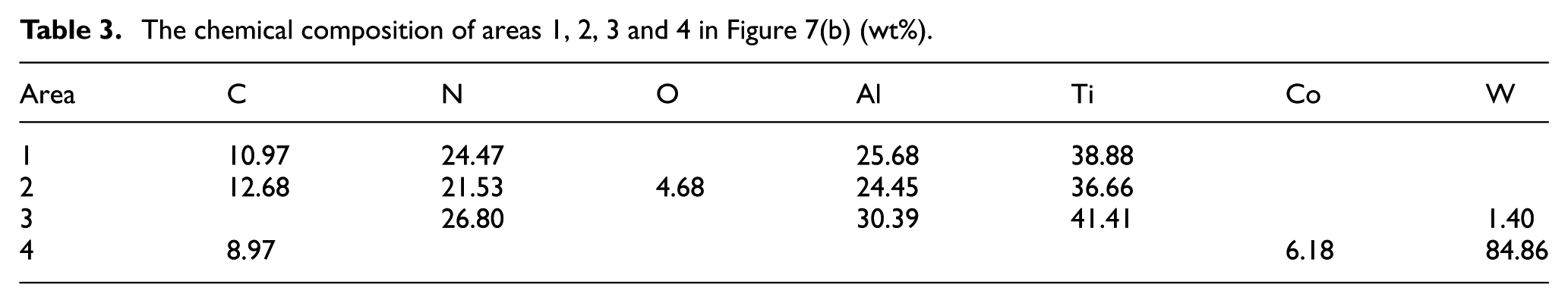
Figure 9 displays the worn morphologies of the diamond-coated tool after high-speed milling graphite. Coating delamination and chipping appeared on the side flank face, concave structure showed up on the cutting edge after spalling of diamond coating and irregularly zigzag wear pattern presented on the side flank face. Slightly uniform wear pattern was on the rake face resulting from the “polishing” abrasive wear. Tiny wear traces were at the edge of wear land resulting from the “micro-cutting” abrasive wear, as shown in Figure 9(b) and (d). In addition, dark graphite was filled in the diamond intergranular space near the wear land.
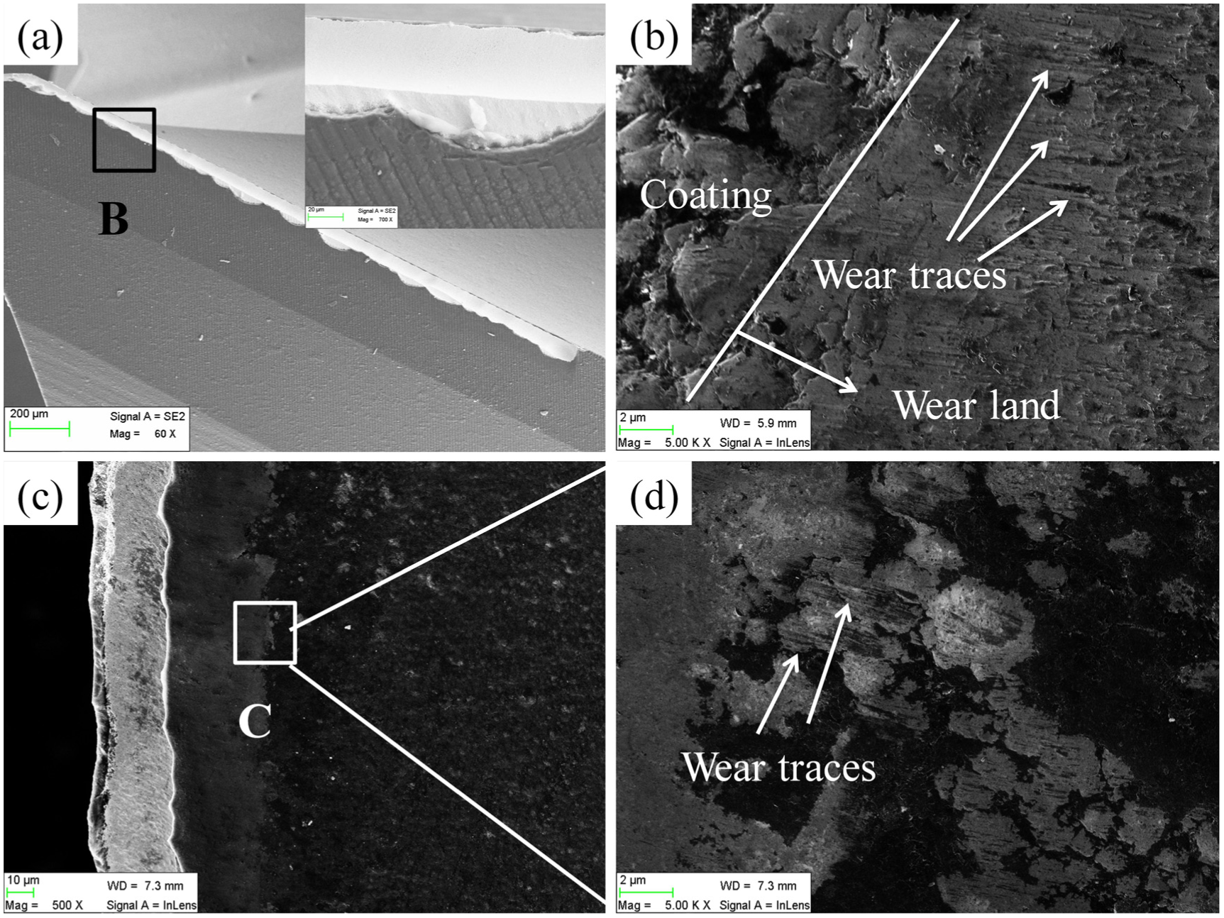
Worn morphology of diamond-coated tool after milling graphite for 1050 m: (a) flank, (b) enlargement of region B in (a), (c) rake and (d) enlargement of region C in (c).
Graphite is a slice layer structure mixed crystal, with carbon atoms in a covalent bond in each layer and combination by Van der Waals force between different layers. It has high friction coefficient (µ = 0.3) when oriented at certain angles to the sliding surface. 25 Fractured craters and residual flake chips on the surface of the workpiece together with graphite chips on the flank and rake faces can result in serious tool abrasive wear during high-speed milling, especially to break carbon atoms with covalent bond. Besides, fatigue produced by the stress and strain distribution changes repeatedly at the tool shaft during machining. Fatigue-related breakage may happened if the cutting force and the stress at the tool shaft increase as a result of tool wear and then stay at that level for an extended period of time. The tool will be broken immediately if the stress is above the endurance limit of the tool, which leads to the coating delamination and chipping. 25
AlTiN and diamond coatings suffer alternation stresses during milling. Cracks, delamination and chipping will be formed during milling. The AlTiN coating is easier to plastic deformation. Therefore, polishing abrasive wear is the primary wear form for the AlTiN-coated tool after chipping of the coating. The diamond coating with higher H3/E*2 value and better resistance of abrasive wear than the AlTiN coating significantly improves tool lifetime. As milling time extension, delamination and chipping occur on diamond coating when suffered stress exceeding coating tolerance. The existence of graphite phase in diamond coating is another reason for diamond coating delamination and chipping. Under the action of impact wear, irregularly zigzag wear pattern appears on the side flank face after delamination and chipping of diamond coating. The rake face mainly suffers compressive stress and friction force from workpiece and chips, respectively. Therefore, relatively uniform wear pattern is on the rake face with the action of “polishing” abrasive wear, as shown in Figure 9.
Cutting force
The cutting forces were monitored during the cutting tests. Cutting force components, Fx, Fy and Fz in the direction of feeding, radial and thrusting, respectively, were measured by a Kistler 3D dynamometer. The average absolute values of Fx, Fy and Fz cutting forces are shown in Figure 10. The three-component forces of the WC tool increase linearly as the milling length extends. For the AlTiN-coated tool, the feeding force increases linearly as the milling length extends and there is no change in the radial and thrusting forces. For the diamond-coated tool, the feeding and radial forces remain within a narrow range when the milling length was less than 425 m and increase when the milling length reached 525 m. The radial force increases linearly as the milling length extends, while the feeding force changes little. The thrust force changes in a narrow range during the whole milling process.
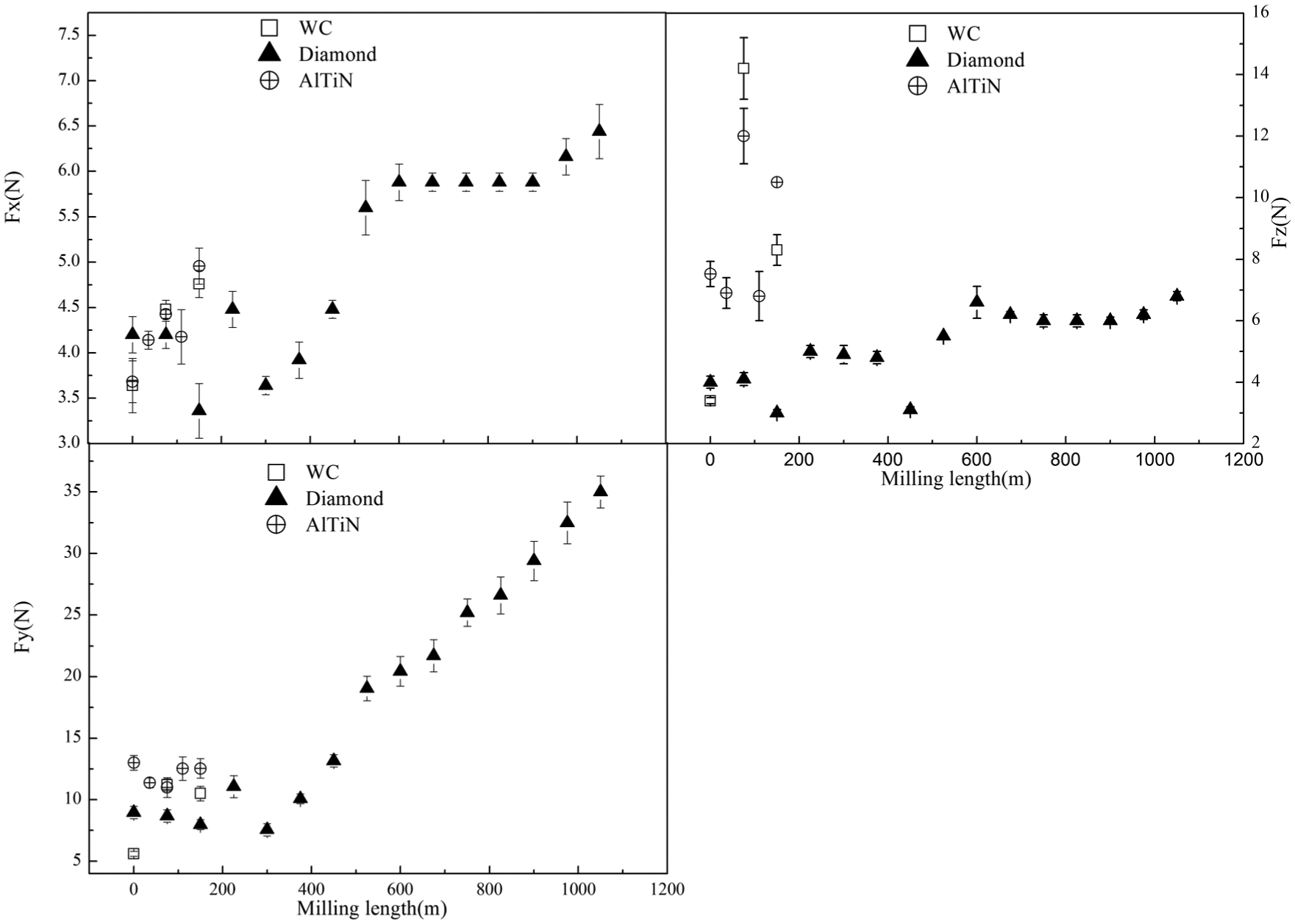
Cutting forces measured during machining.
The flank wear increases when the milling length extends, as shown in Figures 6 and 7. New faces produced on the uncoated and AlTiN-coated tool side flank face increase the contact area of the tool with a machined surface, which increases the cutting forces linearly. The first chipping of diamond coating appears at milling length between 450 and 600 m. The feeding and radial forces increase rapidly at the same time. Whereafter, the WC substrate plays a role in milling directly and wear quickly. Larger concave structure forms on the cutting edges as the milling length extends. This leads to the linear increase in the radial force. Therefore, the chipping of diamond coating induces the rapid increase in cutting force and the formation of concave structure on the cutting edges.
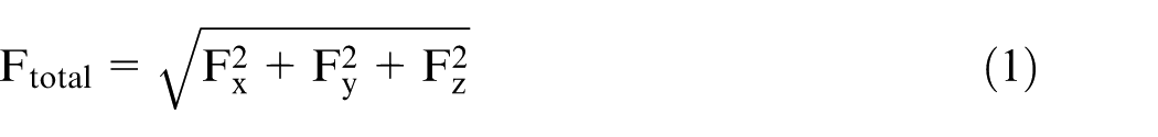
Figure 11 shows the variation trend of the total cutting force with the tool side flank wear. The relationship of Ftotal with Fx, Fy and Fz is shown as formula (1). The total cutting force of the AlTiN-coated tool is higher than that of the diamond-coated tool at the beginning of the machining. This may be attributed to the higher friction coefficient of the AlTiN coating than the diamond coating 10 with graphite and macro-particles on the AlTiN coating surface, as shown in Figure 3. Inversely, the total cutting force of the diamond-coated tool is larger than that of the AlTiN-coated tool after side flank wear value more than 0.06 mm, which is attributed to chipping and concave structure formed on the cutting edge
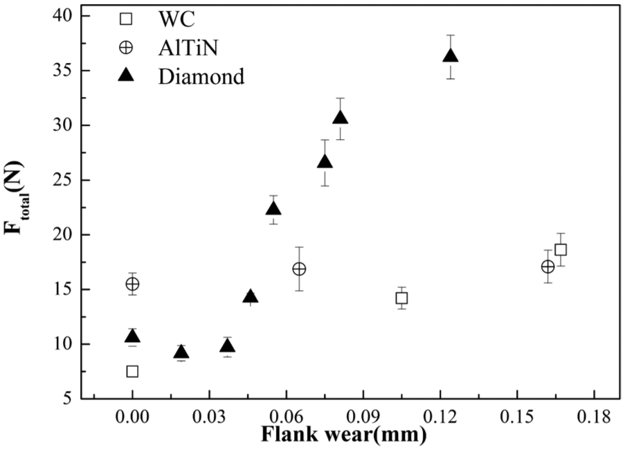
The total cutting force of the coated tools versus the tool side flank wear.
Processed surface roughness
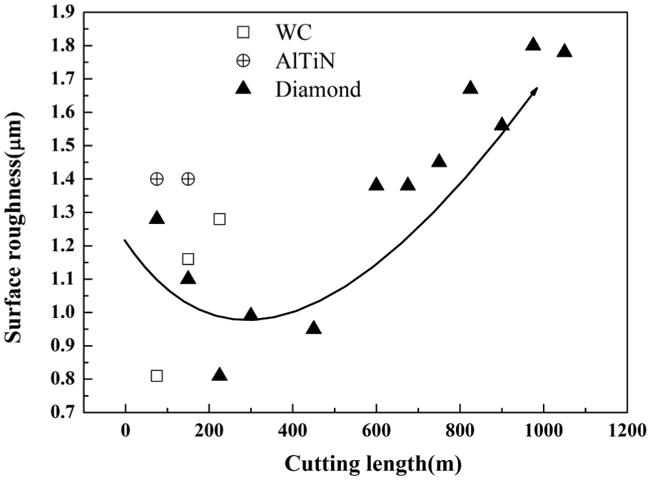
Variations in surface roughness values of graphite workpieces machined by uncoated, AlTiN- and diamond-coated tools on the milling length are shown in Figure 12. Processed graphite surface roughness increases linearly as the milling length extends when machining with WC tool and remains invariable with AlTiN-coated tool. For diamond-coated tool, the surface roughness decreases first and then increases as the milling length extends. A sharp increase is presented when the milling length is 450 and 600 m.
The worked graphite surface roughness values with extended milling length.
Tool wear (Figures 6 and 7) and cutting forces (Figures 10 and 11) increase as the milling length extends. The increase in the cutting forces creates large tool deflections and workpiece geometric accuracy. 26 Identical variation trends between surface roughness and radial force, as shown in Figures 10 and 12, suggest that the radial force is the dominant factor for the increase in worked surface roughness in this study.
The diamond coating surface becomes smoother as it wears with graphite in the earlier stage. The worked graphite surface roughness also decreases in the earlier stage. A sharp increase in the surface roughness value occurs after chipping of diamond coating. Therefore, the chipping of diamond coating not only results in rapid increase in the cutting force but also leads to sharp increase in the worked surface roughness.
Conclusion
AlTiN and diamond coatings were deposited on WC–Co substrates using physical vapor deposition (PVD) and HFCVD reactor. Adhesive strength of both the coating–substrate systems was assessed by indentation test. The machining performance of uncoated, AlTiN- and diamond-coated carbide end-milling tools was evaluated by high-speed milling of EDM graphite. The key conclusions of this work are as follows:
The diamond coating is easier to delaminate and performs lower adhesion than the AlTiN coating under the same load. However, the diamond coating can improve the tool life nearly 10 times compared with AlTiN coating when high-speed milling of EDM graphite.
Delamination and chipping of diamond coating are the chief reasons for the diamond-coated tool quick wear, which leads to rapid increase in the feeding and radial forces as well as the worked surface roughness.
Concave structure on the cutting edges and irregularly zigzag wear are the primary wear patterns on the side flank face for the diamond-coated worn tool. The AlTiN-coated worn tool expresses uniform polishing abrasive wear on the flank face and crater wear on the rake face. The different wear pattern results in the cutting forces exhibiting different variation trend for AlTiN- and diamond-coated tool.
Footnotes
Declaration of conflicting interests
The author(s) declared no potential conflicts of interest with respect to the research, authorship and/or publication of this article.
Funding
The author(s) disclosed receipt of the following financial support for the research, authorship, and/or publication of this article: This work was supported in part by the major national science and technology projects of china (No. 2014ZX04012011) and the major research equipment development projects of National Natural Science Foundation of China (Grant No. 51327902).