
Abstract
In this study, attempts were made to resolve the problem of unstable discharge at the start of electrical discharge machining using the external superimposition method. In general, electrical discharge machining (EDM), the frontal gap distance is controlled by detecting the working voltage. Electrical discharge machining experiments were thus conducted to compare conventional power supplies for electrical discharge machining machines, which superimpose high voltage on the detected working voltage (internal superimposition) with a power supply that superimposes high voltage externally so that no superimposed voltage is added to the detected working voltage (external superimposition). Differences in abnormal discharge rate, discharge frequency, frontal gap distance, and machining characteristics between the two superimposition methods were also investigated. The results showed that external superimposition is better than internal superimposition in that it widens the frontal gap distance immediately after the start of electrical discharge machining, which decreases the abnormal discharge rate to more or less 0 and increases the discharge frequency in a very short time, and that machining characteristics are better with the external superimposition method. Consequently, the effects of the superimposed voltage level on the machining characteristics of electrical discharge machining applying external superimposition were also investigated. It was found that (1) the discharge frequency increases with increasing superimposition voltage, thereby improving the machining rate; (2) the frontal gap distance increases and the surface roughness of the machined surface improves with increasing superimposition voltage; and (3) the tool electrode wear ratio is the smallest when superimposition voltage is around 200 V.
Keywords
Introduction
In electrical discharge machining (EDM), the frontal gap distance is very narrow immediately after the start of machining because the dielectric liquid in the machining gap is very clean. For this reason, the EDM state is prone to become unstable due to short-circuiting, and concentrated discharge occurs very frequently. 1 This poses a huge problem for manufacturing sites. In this article, short-circuiting and concentrated discharge are treated as abnormal discharge. The state of unstable discharge continues for a long time when small discharges are applied because the frontal gap distance is narrow. These problems not only slow down the machining rate extensively but also adversely affect the machined surface properties.2,3 To prevent these problems, modern EDM machines are equipped with high-tech Z axial feed mechanisms that control the frontal gap by monitoring the machining gap conditions. 4 But most manufacturing sites do not have such state-of-the-art EDM machines and are required to resolve those problems using approaches convenient to them. One effective method for improving unstable discharge is minimizing abnormal discharge by widening the frontal gap distance between the tool electrode and workpiece immediately after the start of machining. Some methods of widening the frontal gap distance include increasing the servo voltage or implementing high-voltage superimposition using conventional power supply for EDM machines (hereafter called internal superimposition).5,6 Some have attempted to control the electric discharge position during EDM by applying high-voltage superimposition locally. 7 However, all these studies only investigate the effects of applying the working voltage quite some time after the start of EDM, and there have been no studies on the effects of the working voltage applied immediately after the start of machining and voltage application methods on machining.
Frontal gap distance is controlled by detecting the working voltage during machining and controlling the average working voltage to the preset servo voltage. As described in “Effects of differences in working voltage detection method on frontal gap distance control,” the average working voltage fluctuates immediately after the start of machining because abnormal discharge occurs very frequently. In internal superimposition, the average working voltage fluctuates intensely due to the high-voltage superimposition added to the detected working voltage, which most likely contributes to unstable discharge at the start of machining. On the other hand, in external superimposition, the Z-axis controls the frontal gap so that the average working voltage fluctuates less than internal superimposition. This suggests that external superimposition may reduce abnormal discharge.
The discharge state is estimated by the discharge frequency and abnormal discharge rate. Immediately after the start of machining, the discharge frequency is small, and it then increases with increasing debris concentration in the frontal gap and remains steady at a certain value in the machined area. 8 The frontal gap distance expands due to the debris concentration in the frontal gap with increasing discharge frequency, 9 preventing abnormal discharge from occurring. This means that the discharge state can be assumed to be good if the frontal gap distance expands and the abnormal discharge rate decreases immediately after the start of machining, as these conditions realize a constant discharge frequency in a very short time.
This article investigates the influence of adding and not adding the detected working voltage to the superimposition voltage at the start of machining on die-sink EDM. First, the effects of applying superimposition voltage and the differences between internal and external superimposition were investigated by comparing the changes in discharge frequency, abnormal discharge rate, and frontal gap distance with time from the start of machining. Moreover, machining characteristics such as machining rate, tool electrode wear ratio, and machined surface roughness were also compared. Next, the effects of the superimposition voltage level in external superimposition on machining characteristics were reviewed.
Effects of differences in working voltage detection method on frontal gap distance control
Figure 1 shows the discharge waveform. The discharge voltage waveform equation consists of open voltage ui, ignition delay time td, discharge voltage ue, discharge duration te, pulse interval to, and the voltage of pulse interval uo (more or less 0 V) applied. The average working voltage U can be calculated using equation (1) for comparing the servo voltage. In addition, generally the control speed of the Z-axis of the EDM machine (hereafter called Z-axis) increases when the difference between the set servo voltage and average working voltage is greater. For this reason, the controlled state of the Z-axis becomes unstable when the frontal gap distance is smaller. If the dielectric liquid is very clean immediately after the start of machining, discharge does not occur if the frontal gap distance is more than 4 μm, 8 but occurs when the frontal gap distance is narrow less than 4 μm. Consequently, as the frontal gap distance at the start of machining is narrow less than 4 μm, this is thought to cause frequent abnormal discharge. Frequent abnormal discharge causes open voltage, ignition delay time, and discharge voltage to become low,10,11 resulting in low average working voltage, as shown in equation (1). To prevent this, the frontal gap distance is increased, but because the debris concentration at the start of machining is low, even the slightest rise of the Z-axis will disable discharge. 12 For this reason, the EDM machine is controlled so that the average machining voltage rises suddenly and the frontal gap distance becomes narrow rapidly. However, if the machining gap condition does not change, discharge will not take place. In addition, abnormal discharge occurs frequently unless the frontal gap distance is decreased to that before the Z-axis was raised
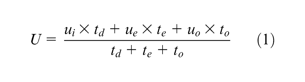
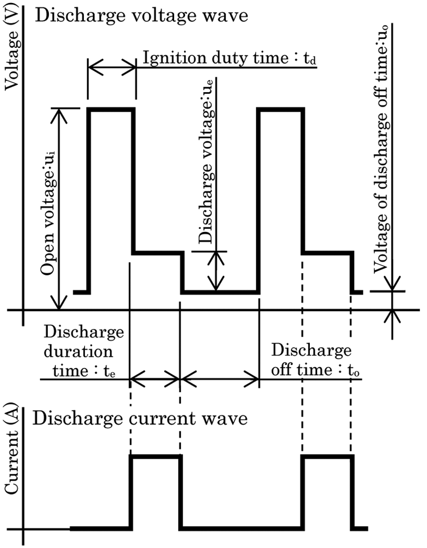
Illustration of discharge voltage and current wave.
where U is the average working gap voltage.
Figure 2 shows the discharge voltage waveform measured between the tool electrode and workpiece for internal and external superimpositions. It can be seen that open voltage rises to nearly 200 V with both methods. Figure 3(a)–(c) shows the average working voltage of internal superimposition, external superimposition, and no superimposition, respectively. They also show the change, from 0.5 s after the start of machining, in the average working voltage of internal superimposition, external superimposition, and no superimposition obtained by 0.2 ms sampling the discharge voltage measured at the detecting point of the EDM power supply for controlling the frontal gap distance, as shown in Figure 4(a). The tool electrode is a φ8-mm copper rod, the superimposed voltage is 280 V for both methods, and the servo voltage is 40 V. With external superimposition (Figure 3(b)), it can be seen that no high voltage superimposed by the external power supply is detected, and the maximum average working voltage is 120 V, which is the open voltage set on the EDM machine. Moreover, it is can be seen in Figure 3(b) that the average working voltage is stable at the servo voltage (40 V), and fluctuation of the average working voltage is the smallest and moderate in the case of external superimposition. In contrast, the average working voltage of internal superimposition is very large and it fluctuates intensely from 0 to 250 V. Without superimposition, the average working voltage fluctuates more than that of the external superimposition and does not stabilize near the servo voltage. As mentioned earlier, immediately after machining starts, the movement of the Z-axis fluctuates intensely, causing the unstable discharge state to continue. On the other hand, with external superimposition, the fluctuation of the average working voltage is smaller than that in internal superimposition. Thus, the fluctuation of the movement of the Z-axis is thought to be small and moderate in external superimposition compared to internal superimposition, resulting in a more rapid improvement in the unstable discharge state immediately after the start of machining.
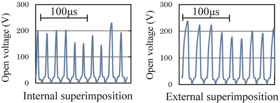
Comparison of detected discharge voltage.
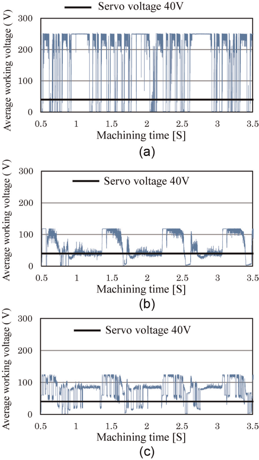
Fluctuation of the average working voltage: (a) internal superimposition, (b) external superimposition, and (c) without superimposition.
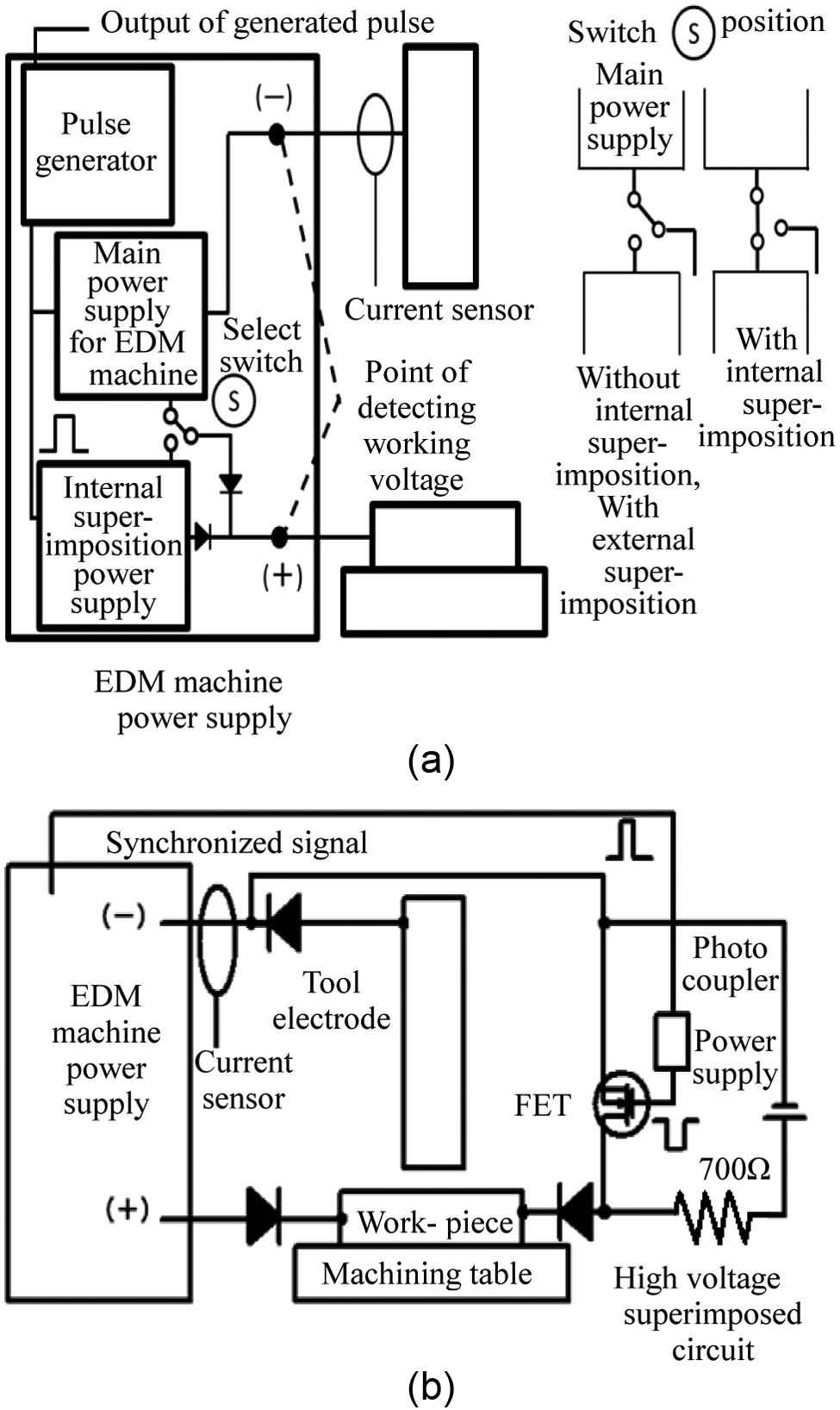
Outline of superimposed open voltage circuit: (a) with internal superimposition and view of EDM machine power supply and (b) with external superimposition.
Experimental system
High-voltage superimposition circuit
Figure 4 shows the high-voltage superimposition circuits used for internal and external superimpositions. For internal superimposition, the EDM power supply shown in Figure 4(a) is used. The power supply consists of a main power supply and superimposition power supply for applying high voltage. There is a switch connected to the superimposition power supply for selecting whether or not to use the superimposition power supply, as shown in Figure 4(a). The superimposition power supply is not used when not applying superimposition and in the case of external superimposition. The working voltage for frontal gap distance control detected at the point voltage is output from the EDM power supply in Figure 4(a). For this reason, in internal superimposition, the applied superimposition voltage is included in the detected working voltage.
In external superimposition, this circuit is connected via diodes to the power supply of the EDM machine to apply superimposition voltage to the machining gap, as shown in Figure 4(b). Due to the use of the diodes, the detected working voltage for controlling the frontal gap distance is not reflected in the superimposed high voltage of the external power supply. Superimposition voltage is applied by synchronizing it with the discharge pulse using the gate signal of the EDM machine’s power supply. A constant voltage constant current DC power supply, which can be continuously varied between 0 and 600 V, was used. To prevent the effects of current from the high-voltage superimposition circuit on machining, a 700-Ω resistor was inserted in the high-voltage superimposition circuit to reduce the current flowing from the superimposed side of the circuit to less than 0.03 A during discharge.
Measurement of abnormal discharge rate
It has been reported that the voltage waveform of the abnormal discharge does not rise to the preset open voltage, 10 as shown in Figure 5(a), thereby enabling differentiation between normal and abnormal discharge because the discharge voltage of abnormal discharge is lower than that of the normal discharge. 11 Thus, in preliminary experiments, the discharge voltage waveforms of abnormal discharge and normal discharge were compared. The results revealed that for abnormal discharge, the discharge voltage is less than 19 V, lower than that of normal discharge, which is 22 V (Figure 5(a)). Based on these results, a circuit discharging abnormal discharge voltage less than 20 V (Figure 5(b)) was built in this study. As shown in Figure 5(c), the abnormal discharge frequency is calculated by counting the AND output of the abnormal discharge signal and discharge current waveform, and the abnormal discharge frequency by dividing the number of abnormal discharges with the machining time. When the discharge voltage is less than 20 V, as signals are output as abnormal discharge, short-circuiting without discharge voltage is also counted as abnormal discharge. The discharge is calculated by counting the signal of the current sensor and the discharge frequency by dividing the number of discharges with the machining time. The abnormal discharge rate is defined as the percentage of abnormal discharge frequency making up the discharge frequency.
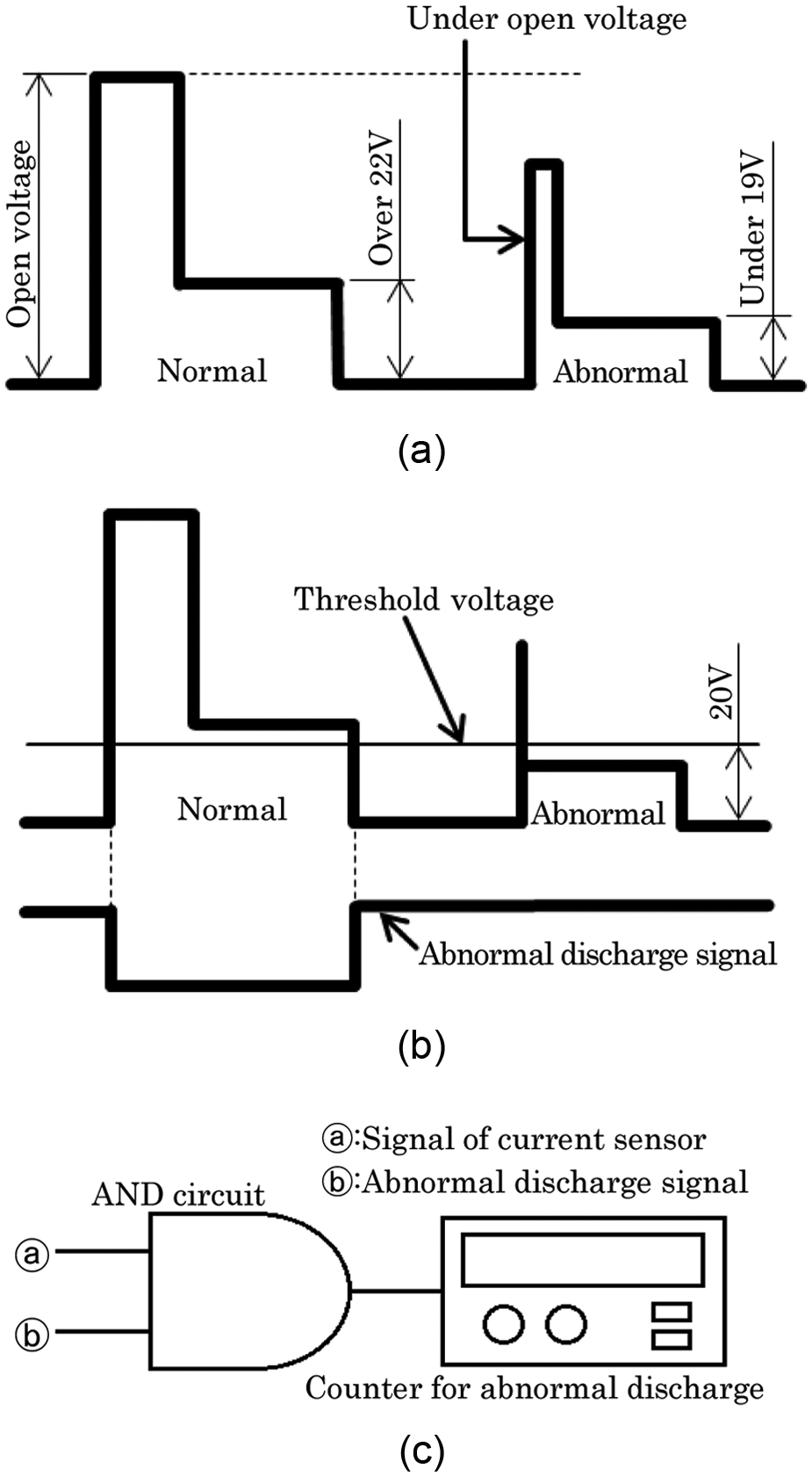
Method of abnormal discharge count: (a) comparison of normal and abnormal discharge voltage wave, (b) abnormal discharge signal, and (c) abnormal discharge count.
Measurement of frontal gap distance
The frontal gap distance during machining, thought to be strongly related to the generated abnormal discharge, was also measured. Figure 6 outlines the method for measuring the frontal gap distance. The movable part of the Z-axis was attached with a measuring plate for measuring the frontal gap distance, and the Z-axis column was attached with an electric micrometer probe. The part of the measuring plate touching the probe was pasted with an insulating sheet to prevent the current from flowing to the micrometer during EDM. The probe (Mitutoyo, MCHP-341) of the electric micrometer (Mitutoyo, M400) used had a measuring resolution and linearity of 0.1 μm and ±2 mm, respectively. Measurement could be carried out sufficiently even at the micrometer order in this study. Due to the risk of the measuring accuracy deteriorating as a result of discharge noise, the enhanced resolution function of a digital oscilloscope was used to measure the movement of the tool electrode. This function is able to reduce specified waveform noises to improve the measuring resolution.
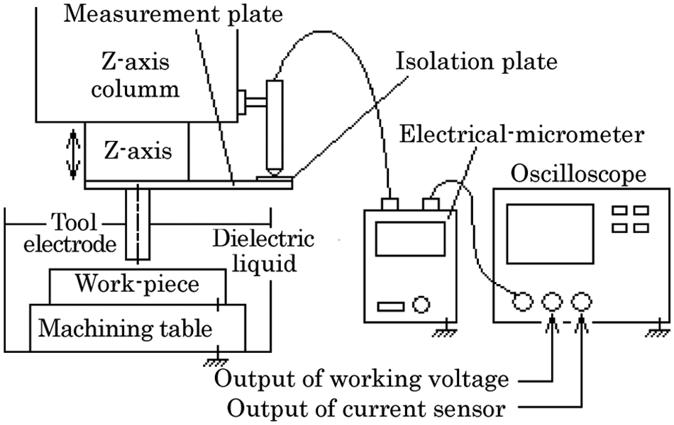
Illustration of measurement method of gap width.
Figure 7 shows an example of the results of measuring the actual frontal gap distance. Figure 8 shows the results of investigating the relation between the servo voltage and frontal gap distance to verify the reproducibility of the frontal gap distance using this method and the measuring accuracy. It can be seen that the variability of the frontal gap distance is about 1 μm for each servo voltage. These results demonstrate the reproducibility of this measurement method and confirm that the measurement of frontal gap distance is highly accurate.
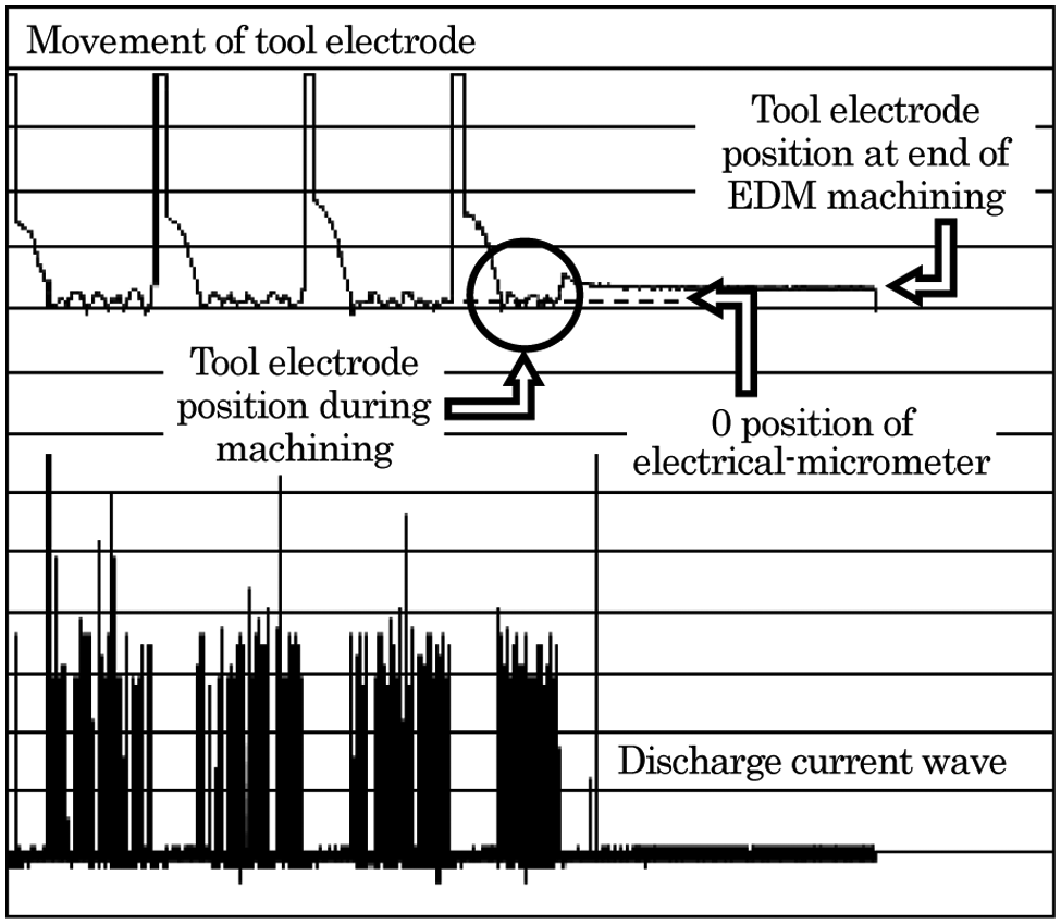
Moving Z-axis and discharge current wave (after removal of discharge noise).
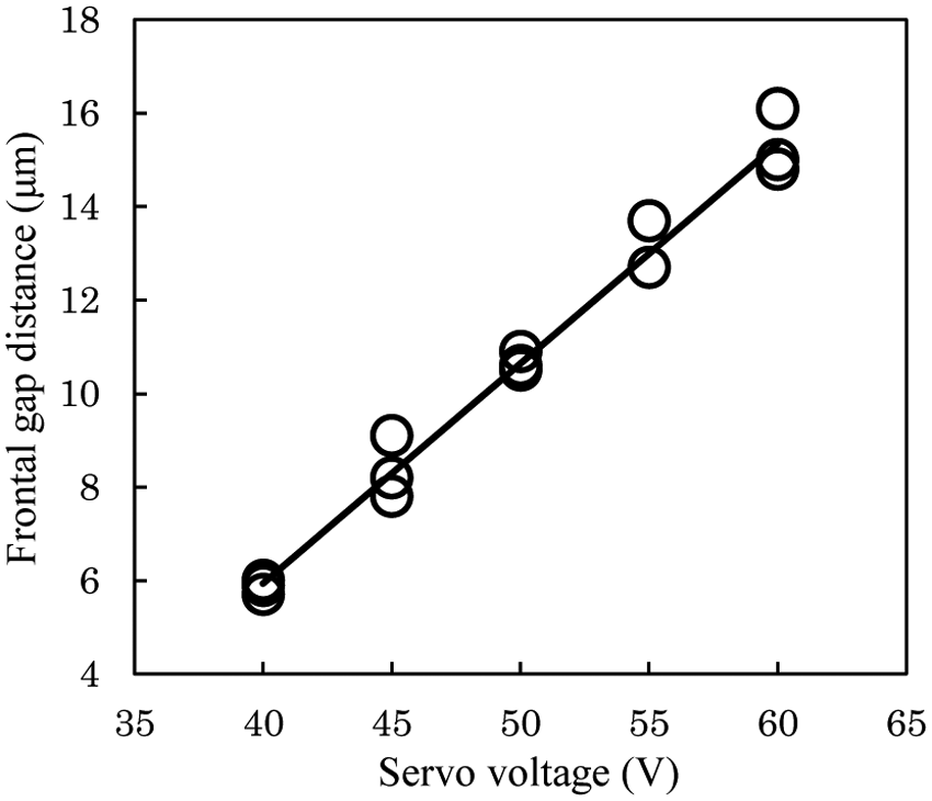
Influence of servo voltage on frontal gap distance.
Comparison of internal and external superimpositions
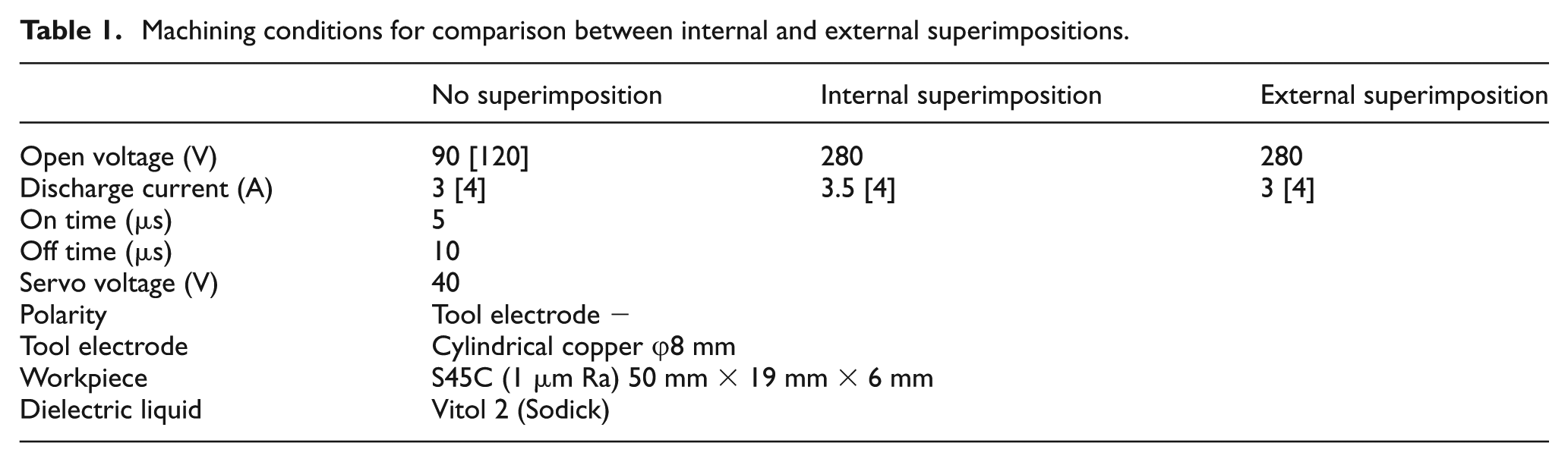
Table 1 shows the experimental conditions. A φ8-mm copper rod was used for the tool electrode and a length of about 50 mm × 22 mm × 6 mm steel sheet (S45C) was used for the workpiece. The edges of the tool electrode were finished using a lathe in each machining process to eliminate the effects of the preprocesses. Both sides of the workpiece were ground to the surface paralleime, flatness, and surface roughness of less than 1 μm Ra to enhance the experiment accuracy. The superimposition voltage was set at 280 V in both internal and external superimpositions. The die-sinking EDM machine used was the Sodick AQ-35LR. Experiments were carried out with the tool electrode and workpiece facing each other in the dielectric liquid, as shown in Figure 4. Machining was performed for 15 min with the tool electrode moved down along the Z-axis. The tool electrode was set as the cathode and the workpiece as the anode. In the comparison of machining characteristics, the machining conditions shown in brackets [ ] in Table 1 were used to obtain the same discharge current, and machining was carried out for 30 min. As shown in Table 1, the machining current was made 0.5 A greater in internal superimposition than external superimposition. This is because in the machining power supply circuit of the EDM machine, a current of at least 0.5 A was added when superimposition voltage was added. The effects of the difference in this current are discussed later.
Machining conditions for comparison between internal and external superimpositions.
Comparison of stable discharge
As mentioned, the discharge stability can be evaluated by investigating the changes in discharge frequency and abnormal discharge rate with time from the start of machining. Figure 9 shows the changes in discharge frequency with time from the start of machining for when no superimposition voltage is applied and for when internal or external superimposition is applied. With no superimposition, the discharge frequency is between 1/10 and 1/20 for both superimpositions at all machining times. This confirms that the superimposed voltage added to the machining gap effectively increases the discharge frequency. Without superimposition, the discharge frequency becomes constant at 1000 times/s 30 s after the start of machining, after which the discharge frequency gently increases. Next, internal and external superimpositions were compared. For both superimpositions, the discharge frequency number did not differ 1 s after the start of machining, and the discharge frequency became stable at 20,000 times/s eventually. The difference in discharge frequency was large between internal and external superimpositions by 100 s after the start of machining. In internal superimposition, the discharge frequency became stable at 20,000 times/s 120 s later. On the other hand, with external superimposition, the discharge frequency became stable less than 6 s later. As mentioned earlier, when discharge becomes stable, the discharge frequency becomes stable at a certain value depending on the machined area and frontal gap distance. 8
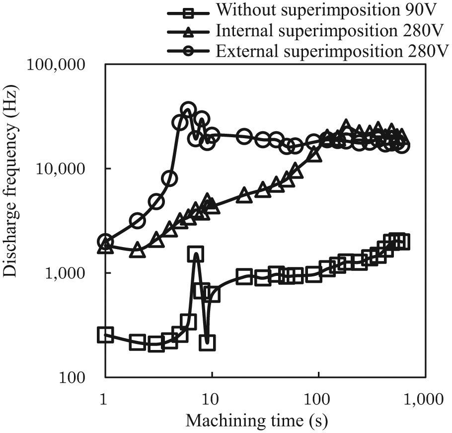
Transition of discharge frequency.
Next, the changes in abnormal discharge rate with time from the start of machining were investigated for when no superimposition voltage is applied, and for when internal or external superimposition is applied. Figure 10 shows the results. When there is no superimposition voltage, the abnormal discharge rate becomes very large, at over 90%, about 4 s after the start of machining. Around 7 s from the start of machining, it fluctuates intensely between 28% and 90%, suggesting extremely unstable discharge conditions. Eventually, the abnormal discharge rate gently decreases after 30 s from the start of machining. Next, internal and external superimpositions were compared. For both methods, the abnormal discharge rate was about 22% 1 s after the start of machining, and the discharge frequency was the same. Consequently, it is thought that machining gap conditions are the same in both internal and external superimpositions. Although mentioned later, frontal gap distance of under 4 μm could be achieved using both superimposition methods. But the difference occurred after 100 s from the start of machining. Specifically, with internal superimposition, the abnormal discharge rate becomes more or less 0 more than 100 s later. On the other hand, with external superimposition, the abnormal discharge rate becomes more or less 0 6 s later. These findings clarify that discharge is more stable in external superimposition than in internal superimposition immediately after the start of machining.
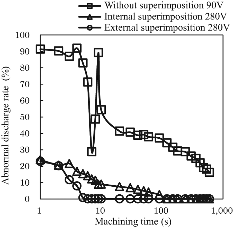
Transition of abnormal discharge rate.
Comparison of frontal gap distance
The changes in frontal gap distance with time from the start of machining were investigated, and it was found that the control of the frontal gap distance of the Z-axis fluctuates very frequently and minutely 5 s from the start of machining. In particular, fluctuation in internal superimposition was large because the Z-axis was moving violently. This may be due to the conspicuous changes in the average working voltage as described in Figure 3(a). Figure 11 shows the changes in the frontal gap distance 5 s after the start of machining for when no superimposed voltage is applied, and for internal and external superimpositions. From Figure 11, it can be seen that the frontal gap distance is about 4 μm 5 s after the start of machining in all the machining experiments, suggesting that the frontal gap distance is less than 4 μm at the start of machining. With no superimposition, 5 s after the start of machining, a small increase was seen, but no major changes were seen until 600 s later. This suggests that machining continues consistently when the frontal gap is 6 μm. Next, internal and external superimpositions were compared. Ten seconds after the start of machining, the frontal gap distance in internal superimposition was about 5 μm versus 15 μm in external superimposition, clarifying that superimposing high voltage has a huge influence on the frontal gap distance.
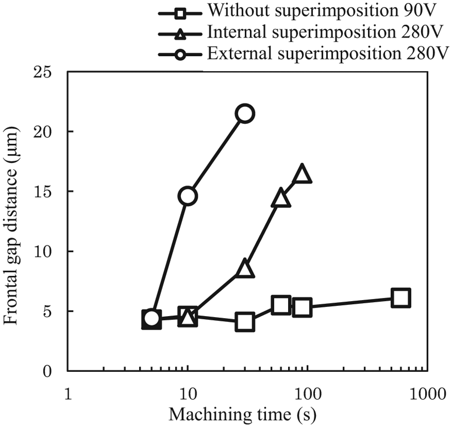
Transition of frontal gap distance.
Next, Figures 10 and 11 review the controlled state of the frontal gap distance of the Z-axis 5 s from the start of machining. The frontal gap distance in internal superimposition does not increase even if high voltage is superimposed, due to the small rate of decrease in the abnormal discharge rate, as shown in Figure 10. In addition, as shown in Figure 11, the frontal gap distance does not change 5–10 s after the start of machining, confirming that the frontal gap distance has not widened. On the other hand, in external superimposition, the frontal gap distance widens quickly due to the rapid decrease in the abnormal discharge rate 2 s after the start of machining (Figure 10), and the frontal gap distance rapidly increases 5 s after the start of machining, as shown in Figure 11, suggesting that the frontal gap distance increases 2 s after the start of machining. Because the fluctuation in the average working voltage in external superimposition is smaller than that in internal superimposition as described in Figure 3(a) and (b). Therefore, the movement of the Z-axis is small and moderate with external superimposition. As a result, the discharge frequency increases immediately after the start of machining, leading also to the increase in the concentration of the debris in the frontal gap. This may be because the abnormal discharge rate decreases quickly due to the widening of the frontal gap distance, supporting the results of Figures 3 and 9–11. These results confirm that the state of unstable discharge improves rapidly in external superimposition than that in internal superimposition.
Next, the influence of the frontal gap distance on the abnormal discharge rate is reviewed in Figures 10 and 11. The abnormal discharge rate becomes 0 more than 100 s after the start of machining in internal superimposition and 6 s after the start of machining in external superimposition (Figure 10). Figure 11 shows that the frontal gap distance at these times is about 16 μm in internal superimposition and about 14 μm in external superimposition. It was found that under these experimental conditions, the frontal gap distance needs to be over 15 μm for the abnormal discharge rate to become 0.
As mentioned earlier in Table 1, the discharge current of internal superimposition is greater than that of external superimposition, and the greater the discharge current, the greater is the machined volume per discharge. As considerable machining debris is generated in internal superimposition, the concentration of machining debris in the frontal gap tends to increase easily. This causes the frontal gap distance to increase, allowing stable EDM. The 0.5 A difference seen is comparatively large at 17% compared to 3 A, indicating that internal superimposition is more advantageous for realizing stable discharge. However, the discharge state becomes stable immediately after the start of machining, confirming that external superimposition is effective for stabilizing discharge at the start of machining.
Comparison of machining rate
As discussed, EDM stability improves by applying superimposition, with stability improving immediately after the start of machining in the case of external superimposition than internal superimposition. This is thought to also influence machining characteristics such as machining rate, tool electrode wear ratio, and machined surface roughness. For this reason, the effects of adding high superimposed voltage and superimposition method on machining characteristics were investigated. As mentioned earlier, the experimental conditions shown in brackets [ ] in Table 1 were used to obtain the same discharge current.
First, Figure 12 shows the results of comparing the machining rate. The machining rate increases when superimposed voltage is applied. In the case of external superimposition, the machining rate increased by 1.2 times and about 3 times compared to internal superimposition and without superimposition, respectively. This may be because with external superimposition, the discharge frequency increases and the abnormal discharge ratio decreases immediately after the start of machining, as shown in Figures 9 and 10.
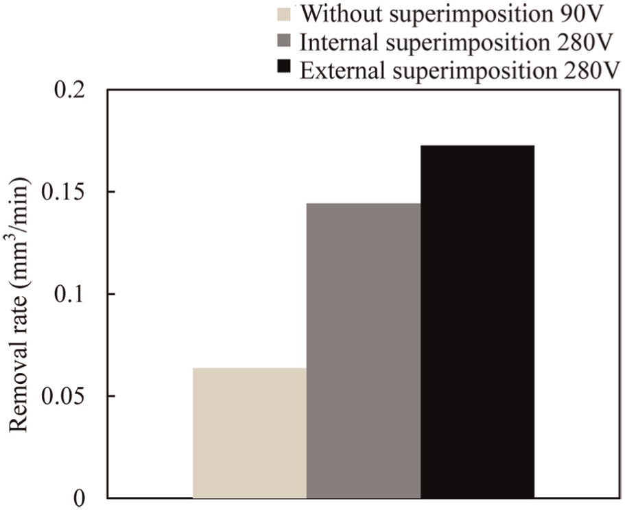
Comparison of machining rate.
Comparison of tool electrode wear ratio
Figure 13 compares the tool electrode wear ratio between external and internal superimpositions. It can be seen that tool electrode wear ratio is smallest with external superimposition. This is because, as shown in Figure 10, abnormal discharge frequency decreases immediately after the start of machining and the degree of which is larger in external superimposition than in internal superimposition.
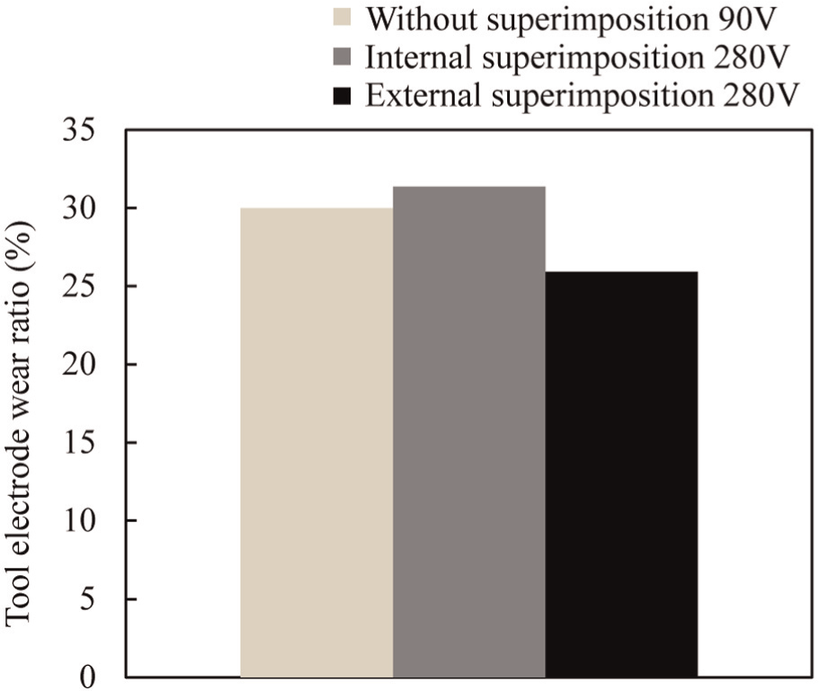
Comparison of tool electrode wear ratio.
Comparison of machined surface roughness
Figure 14 shows the comparison of the machined surface roughness. As shown in Figure 14, the surface roughness tends to improve with high-voltage superimposition, and it improves more with external superimposition compared to internal superimposition. These results confirm the predominance of the external superimposition method as it stabilizes machining conditions immediately after the start of machining.
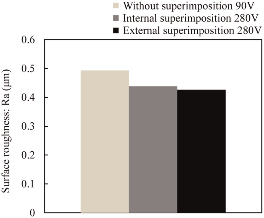
Comparison of surface roughness.
Effects of superimposed voltage level on machining characteristics
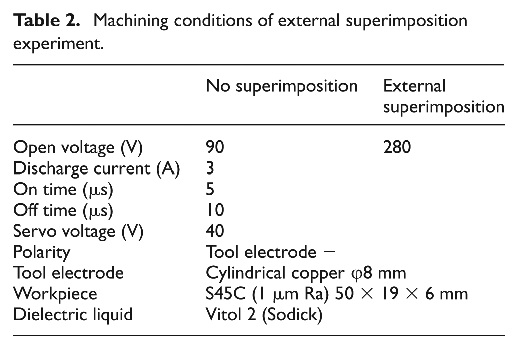
Next, the effects of the externally superimposed voltage value on machining characteristics were studied. Table 2 shows the experimental conditions. The discharge current is 3 A. Three superimposed voltages were used: 200, 300, and 400 V. When no superimposed voltage was applied, an open voltage of 90 V of the EDM machine power supply was applied to the frontal gap. The servo voltage was set at 40 V. Although a copper rod was used as the tool electrode, two types of electrodes (φ8 mm and φ16 mm) were used to determine the effects of the difference in the tool electrode area on machining characteristics. The workpiece surface was also ground in this experiment, and the edges of tool electrode were finished with a lathe after each preprocess to eliminate the effects of the preprocesses. The tool electrode was set as the cathode and the workpiece as the anode.
Machining conditions of external superimposition experiment.
Machining rate
Figure 15 shows the effects of superimposed voltage on machining rate. It can be seen that the machining rate increases with increasing superimposition voltage regardless of the tool electrode area. In particular, this can be conspicuously seen with the φ16-mm tool electrode. At the superimposition voltage of 400 V, machining rate was found to improve by 14 times compared to machining without applying superimposition voltage. Figure 16 shows the effects of superimposition voltage on the discharge frequency. It can be seen that the discharge frequency increases with increasing superimposition voltage, and this increase resembles the increase in the machining rate in Figure 15. As shown in Figure 10, with external superimposition, the abnormal discharge rate decreases to more or less 0% 6 s after the start of machining. These results were obtained for machining carried out for 30 min. In Figure 15, there is more or less no influence of abnormal discharge, and the increase in machining rate is due to the increase in discharge frequency.
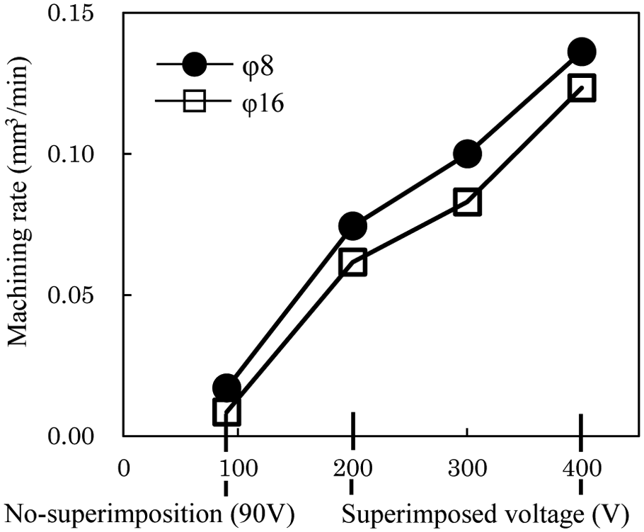
Influence of superimposed voltage level on machining rate.
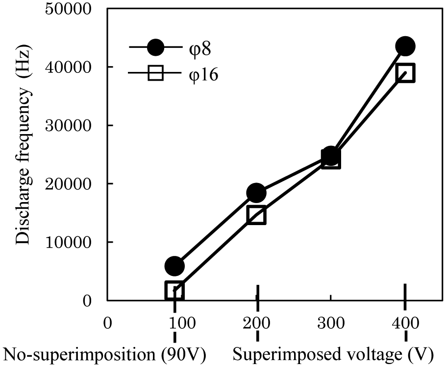
Influence of superimposed voltage level on discharge frequency.
Frontal gap distance
Figure 17 shows the effects of superimposition voltage on frontal gap distance. It can be seen that regardless of the tool electrode area, the frontal gap distance increases with increasing superimposition voltage. Because the debris concentration in the machining gap increases with increasing discharge frequency, discharge becomes stable when the superimposed voltage is higher.
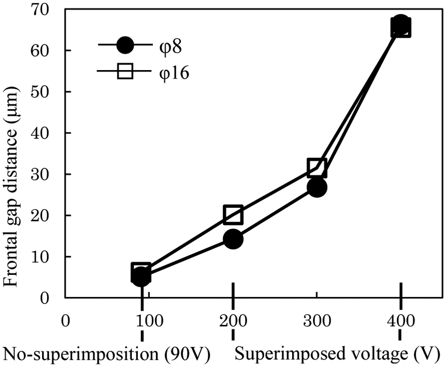
Influence of superimposed voltage level on frontal gap distance.
Surface roughness
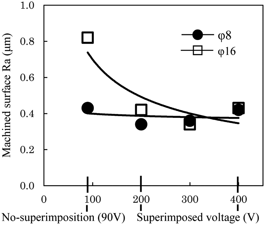
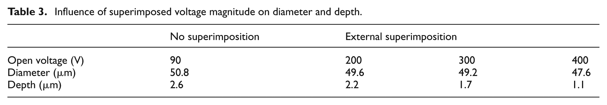
Figure 18 shows the effects of superimposition voltage on surface roughness. It can be seen that with the φ8-mm tool electrode, when the superimposition voltage increases, the surface roughness tends to improve. On the other hand, with the φ16-mm tool electrode, the surface roughness is poor if no superimposition voltage is applied. However, when the superimposition voltage is above 200 V, the surface roughness improves to less than half of that when superimposition voltage is not applied. The deterioration in surface roughness when no superimposition voltage is applied may be due to the frequent occurrence of abnormal discharge resulting from the short frontal gap distance, as shown in Figure 17. One of the reasons why surface roughness improves when superimposition voltage is applied may be as follows: Table 3 shows the average depth and diameter of the discharge crater for 30 single-pulse discharge craters generated using various superimposition voltages with a φ8-mm tool electrode. Figure 19 shows photographs of craters caused by single-pulse discharge at each high-voltage condition The craters were measured using a high magnification rate microscope (Mitutoyo, MF-UA10-10THD) and measurement along the depth was carried out using the depth of focus method. As shown in Table 3, these values indicate that increasing the superimposition voltage decreases the diameter of the single-pulse discharge craters, indicating a tendency for the depth to decrease. It is known that the wider the frontal gap distance, the shallower13–15 and smaller 16 will single-pulse discharge craters be. Hayakawa et al. 15 reported that increasing the frontal gap decreases the plasma current density due to which the plasma diameter of the arc column will be increased, resulting in shallow single-pulse discharge craters. Kojima et al. 16 found through observation of the plasma of the arc that increasing the frontal gap increases the plasma diameter, and as the thermal flux flowing between the electrodes decreases, the wear area of the electrode decreases. The results of Table 3 support these findings.
Influence of superimposed voltage level on machined surface.
Influence of superimposed voltage magnitude on diameter and depth.
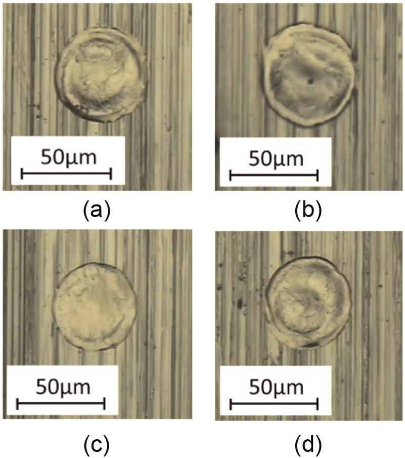
Single-pulse discharge craters: (a) 90, (b) 200, (c) 300, and (d) 400 V.
Tool electrode wear rate
The effects of superimposition voltage on the tool electrode wear rate for φ8-mm and φ16-mm tool electrodes were investigated. Figure 20 shows the results. At the superimposition voltage of around 200 V, wear became minimum regardless of the tool electrode area. However, when the superimposition voltage was high, there was a tendency for wear to increase. Ueide and Hashiguthi 17 reported that increasing the frontal gap distance decreases the discharge energy distributed to the positive and negative electrodes, but the degree of distribution is greater in the positive electrode than the negative electrode. Consequently, when the frontal gap distance increases, it means the negative electrode is machined more than the positive electrode. In other words, the tool electrode is machined more. Figure 20 shows the results supporting this. When superimposition voltage is not applied, the φ16-mm tool electrode wear is especially bad, probably because the frontal gap distance is short, causing abnormal discharge to occur more frequently. It is also known that the wear of the tool electrode increases with increasing thermal flux flowing to the tool electrode in intensive discharge.
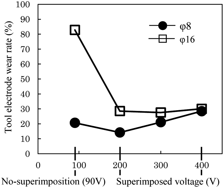
Influence of superimposed voltage level on tool electrode wear ratio.
Summary
In this study, first the effects of applying superimposition voltage and the difference between internal and external superimpositions on discharge frequency, abnormal discharge rate, and frontal gap distance were investigated. The results showed that abnormal discharge rate decreases and the discharge frequency rapidly increases from an early stage after machining starts when superimposition voltage is applied. This decrease is conspicuously faster with external superimposition than internal superimposition, because the frontal gap distance increases faster with external superimposition. This means that discharge and machining characteristics are more stable with external superimposition. Furthermore, machining characteristics such as machining rate, tool electrode wear ratio, and machined surface roughness were compared, and the following results were obtained:
The machining rate increases with superimposition and is faster with external superimposition than internal superimposition.
The tool electrode wear ratio is smallest with the external superimposition.
The machined surface roughness tends to improve when the superimposed voltage increases. In addition, surface roughness is better with external superimposition than internal superimposition.
EDM by external superimposition was thus carried out to investigate the effects of superimposition voltage on machining characteristics and the following were clarified:
The machining rate increases with increasing superimposition voltage regardless of the tool electrode area. Particularly with the φ16-mm tool electrode, the machining rate was 14 times faster with 400-V high-voltage superimposition than when no superimposition voltage was applied.
The discharge frequency increases with increasing superimposition voltage.
The frontal gap distance has a direct relation with superimposition voltage, where the frontal gap distance increases with increasing superimposition voltage.
For both the φ8-mm and φ16-mm tool electrodes, the surface roughness improved with increasing superimposition voltage. In particular, with the φ16-mm tool electrode, surface roughness improved to below half that without superimposed voltage.
Tool electrode wear was minimum regardless of the tool electrode area at the high superimposition voltage of around 200 V. When above 300 V, there was a tendency for wear to increase.
Footnotes
Acknowledgements
The authors would like to express their heartfelt appreciation to Mr Tomohiko Kitamura of the Lubricants Research Laboratory of Idemitsu Kosan Co., Ltd, for his extensive support in this study.
Declaration of conflicting interests
The authors declare that there is no conflict of interest.
Funding
This study was partly financial supported by a study donation from Idemitsu Kousan Co., Ltd.