
Abstract
High-speed face milling of hardened steel was conducted to investigate the effects of cutting parameters on chip morphology and tool wear. It was found that the tool–chip contact length decreased substantially as the cutting speed increased over 2000 m/min. The adiabatic shear theory is more suitable for describing the formation of individual saw-tooth obtained in the present study. When the cutting speed was relatively low, relatively long tool life can be obtained at large radial depth of cut. On the contrary, when the cutting speed was relatively high, smaller radial depth of cut was beneficial for the acquisition of longer tool life. When the cutting speed was relatively low, due to relatively high mechanical load at relatively small radial depth of cut, large flaked region arose on the tool rake face and the main wear mechanisms of the tool flank face was fracture. However, when the radial depth of cut was relatively large, because of the relatively low mechanical load, there was no flaking on the tool rake face. There existed thermal crack perpendicular to the cutting edge due to the relatively high cutting temperature. When the cutting speed was relatively high, due to the drastically reduced tool–chip contact length, there was very small area of coating delamination near the cutting edge (at relatively small radial depth of cut) or no wear near the cutting edge (at relatively large radial depth of cut).
Introduction
Increasing the chip cross section and increasing the cutting speed are the two ways of enhancing efficiency. However, increasing the cross section is limited because of the stability constraints. For the purpose of enhancing machining efficiency and reducing the costs, high-speed cutting (HSC) technology has been widely used in the field of manufacturing. Many valuable researches1–5 have been conducted in the field of high-speed milling (HSM). With the development of rigid machine tools and tool materials, HSM technology has been applied in hard milling. It was found that hard milling can be an alternative for the grinding process.6,7 According to the work by Siller et al.,
8
the machining operations of molds and dies can be classified into sculptured surface milling (ae≈ap), profile milling (
The saw-tooth chip was frequently observed in high-speed machining process. There exist two theories for the saw-tooth chip formation, namely adiabatic shear theory9,10 and cyclic crack theory.11,12 There have been numerous studies13–16 on the formation mechanism of saw-tooth chip in HSM of hardened steel. However, few of these previous studies were conducted with cutting speed above 2000 m/min. A ball-nose end mill was used by Ning et al. 13 to investigate the chip formation in milling AISI H13 hardened steel. It was found that formation mechanisms of saw-tooth chip were a combination of “crack theory” and “adiabatic shear theory.” Cutting speed ranging from 50 to 1500 m/min were applied by Dolinšek et al. 14 in HSM of hardened tool steel. The experimental results showed that there was a close relationship between the chip parameters, especially in high-speed machining. Wang et al. 15 studied the process of chip formation and the change in chip morphology in HSM of hardened steel. The results indicated that increasing the cutting speed not only strengthened the material’s hardness but also increased the local temperature of the shear band. Experimental investigation of chip formation in high-speed ball-nose end milling AISI H13 hardened steel was conducted by Ning et al. 16 It was found that “adiabatic shear” did not occur in chip formation in the study.
There are many researches on tool wear in the field of HSM of hardened steel. Most of these researches concentrated on sculptured surface milling and profile milling.17–23 Scant studies24,25 have been performed to investigate tool wear in high-speed face milling of hardened steel. HSM of hardened steel was performed by Fallböhmer et al. 17 to identify the cutting tool performance and determine the recommended cutting parameters. Different combinations of cutting parameters were adopted by Ghani et al. 18 in order to study the wear mechanisms of coated and uncoated carbide tools in high-speed end milling of hardened steel. Research was conducted by Urbanski et al. 19 to investigate tool wear in high-speed ball-end milling of hardened steel. Toh 20 investigated different cutting path orientations in HSM of hardened steel. Research results revealed that when a vertical downward orientation was applied, the longest tool life can be obtained. Okada et al. 21 experimentally studied the cutting performance of Polycrystalline Cubic Boron Nitride (PCBN) tool in high-speed end milling of hardened steel. The experimental results showed that the PCBN tools could be used in the field of high-speed hard milling. High-speed end milling of AISI D2 hardened tool steel was performed by Koshy et al. 22 in order to investigate surface roughness and tool wear. Chipping, adhesion and attrition were considered to be the main wear mechanisms of the tool flank face. Pu and Singh 23 experimentally investigated the cutting performance of PCBN tools and coated tungsten carbide in high-speed ball-nose end milling of hardened tool steel. High-speed face milling of AISI H13 hardened steel with PCBN tools used was conducted by Cui et al. 24 to investigate the effects of cutting speed on tool wear. Ultra-high-speed face milling of AISI 1045 hardened carbon steel was performed by Liu et al. 25 to investigate the tool wear patterns and wear mechanisms. It was found that high heat resistance, wear resistance and chemical stability were important for the performance of the cutting tools.
Previous studies provided valuable information about chip morphology and tool wear in HSM of hardened steel. However, it can be found that scant studies on chip formation were carried out with cutting speeds above 2000 m/min. It was also found that relatively few researches on tool wear had been conducted in the field of high-speed face milling. With the development of tool materials and rigid machine tools, increasingly high cutting speed has been adopted in the industries in order to enhance machining efficiency and maintain competitiveness. Cutting speed affects the tool–work interaction greatly. New experimental phenomenon, for example, new type of chip morphology, is expected to arise when higher cutting speed is used. For the purpose of having thorough understanding of the tool wear mechanisms in high-speed face milling, it is essential to investigate the effects of the new phenomenon on tool wear. Since radial depth of cut determines the heating and cooling time of the cutting tool, it affects the tool temperature in face milling process greatly. Tool temperature affects tool wear substantially. However, it can be found from these previous studies that few researches have been performed to investigate the effects of radial depth of cut on tool wear.
Due to the great high-temperature strength and wear resistance, AISI H13 tool steel has been widely applied in extrusion, hot forging and pressure die casting. In the present work, high-speed face milling of hardened AISI H13 steel is conducted to investigate the effects of cutting speed and radial depth of cut on chip morphology and tool wear. In the present study, cutting speeds ranging from 400 to 2400 m/min are used. New type of chip morphology induced by higher cutting speed is identified and analyzed. The effects of new experimental phenomenon on tool wear mechanisms are investigated. The optimum choice of radial depth of cut was also identified for tools tested at relatively low and high cutting speed in terms of tool life. The present work is expected to increase the current understanding of chip formation mechanisms and tool wear mechanisms in high-speed face milling of hardened steel. The present study is conducted to provide valuable information for the engineers who are committed to enhance the cutting tools performance and machining efficiency in high-speed face milling of hardened steels.
Experimental procedures
Workpiece and cutting tool
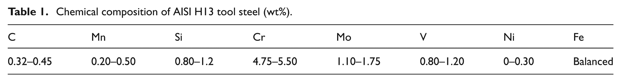
In the present study, AISI H13 hardened steel (46–47 HRC) was used in the milling tests. A block of steel was designed and manufactured, as shown in Figure 1, in order to perform the cutting tests. The chemical composition of the work material was tested prior to the cutting tests. The chemical composition of the steel under consideration was shown in Table 1.
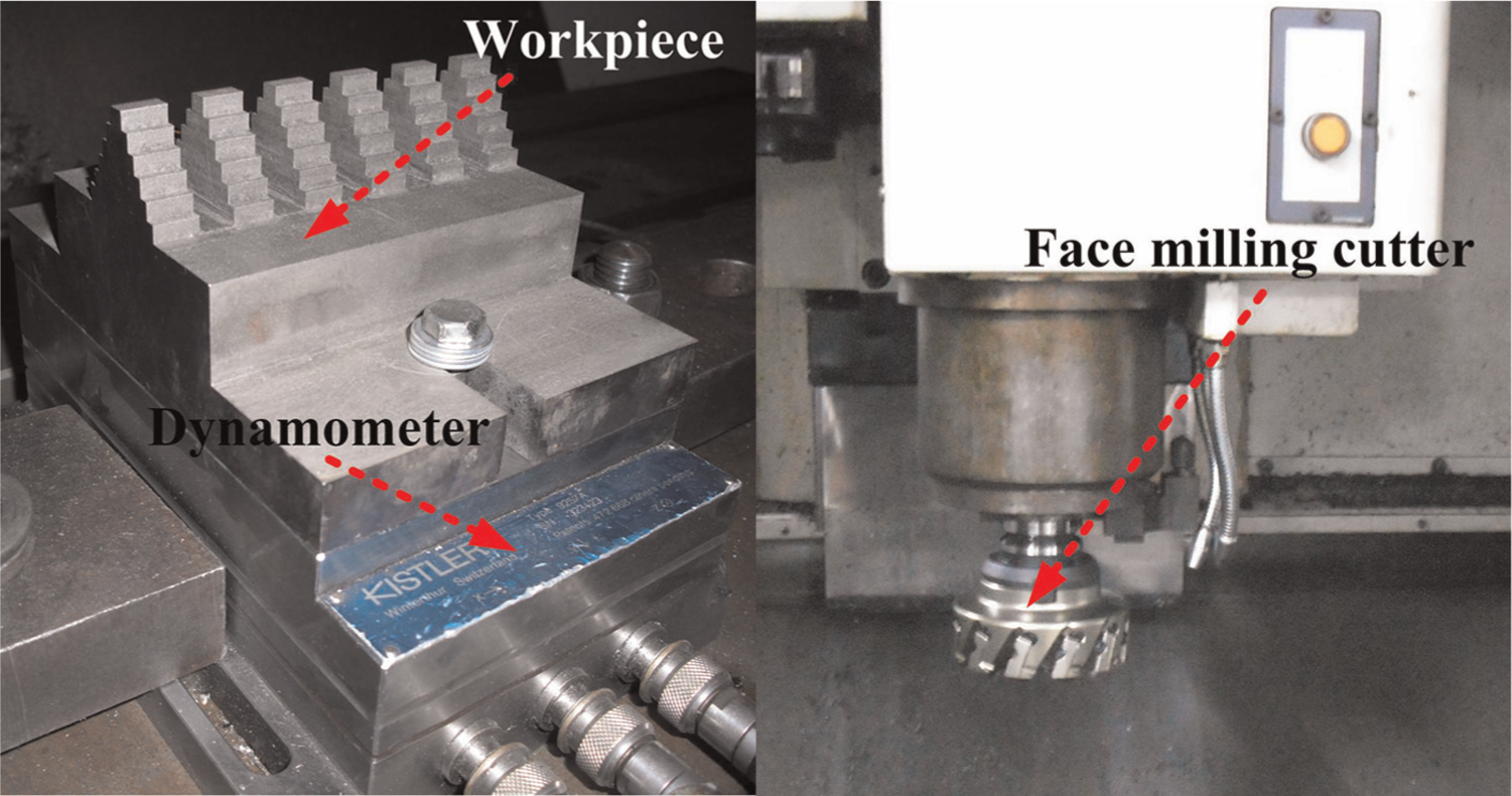
Experimental setup.
Chemical composition of AISI H13 tool steel (wt%).
The tungsten carbide inserts have been applied extensively in machining hardened steel. The inserts recommended by the tool company were used in the present study. Tungsten carbide inserts SEEX 09T3AFTN-D09 (Seco Tool Company) coated with Ti(C, N)–Al2O3 were applied in the milling tests. The tool holder (Seco R220.53-0125-09-8C) had a tool diameter of 125 mm. It is capable of carrying eight inserts. The major cutting edge angle, axial rake angle and radial rake angle of the tool holder were 45°, 20° and -5°, respectively. In each test, only one of the teeth was used to preclude the effects caused by small differences between the teeth. All the milling tests were performed on a vertical computer numerically controlled machining center DAEWOO ACE-V500. The machining center had a maximum spindle rotation speed of 10,000 r/min and a 15 kW drive motor.
Cutting tests
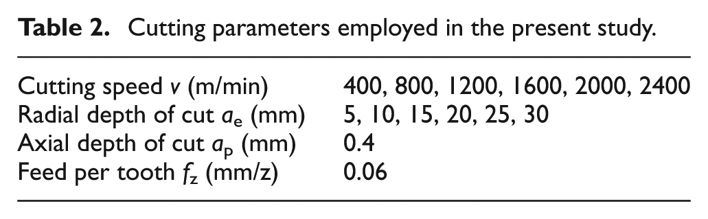
The milling cutter was positioned at the center line of the workpiece. For the purpose of avoiding rapid tool wear, radial depth of cut ae in the range of 5–30 mm at an interval of 5 mm was applied in the present study. Cutting speeds v ranging from 400 to 2400 m/min were used for each value of ae. Axial depth of cut ap and feed per tooth fz were fixed to be 0.4 mm and 0.06 mm/z, respectively. Table 2 shows the cutting parameters employed in the present study.
Cutting parameters employed in the present study.
Each test was repeated three times for given cutting conditions. A Kistler piezoelectric dynamometer (type 9257B) was used to measure the cutting forces in the cutting process. The dynamometer was installed on the machine table, as shown in Figure 1. A multichannel charge amplifier was used to amplify the charge which generated at the dynamometer. The force sensor was filtered to eliminate noises induced by the process variables. The sampling frequency was set to be 10000 Hz. A digital microscope (IMPC, China) was used to examine the tool flank wear periodically. Tool life was recorded as the tool flank wear reached or increased over 0.3 mm. The worn tools were analyzed by means of scanning electron microscopy (SEM) (JSM-6510LV, Japan) and energy-dispersive X-ray spectroscopy (EDS) (JSM-6510LV, Japan) after the cutting tests. The chip was analyzed using digital microscope, SEM and EDS.
Results and discussion
Chip morphology
Figure 2 shows the chip morphologies obtained under different combinations of cutting parameters. It can be seen from Figure 2 that the chip morphology evolved similarly as the cutting speed increased in spite of the variation of radial depth of cut. When the radial depth of cut was below 20 mm, arc-shaped chip formed at the cutting speed of 400 m/min. However, when the radial depth of cut was above 20 mm, long strip of chip appeared at the same cutting speed. Despite the difference of radial of depth, as the cutting speed increased from 800 to 2400 m/min, the chip morphologies changed in the following order: long strip of chip (800 and 1200 m/min) and powder-shaped chip (1600, 2000 and 2400 m/min).
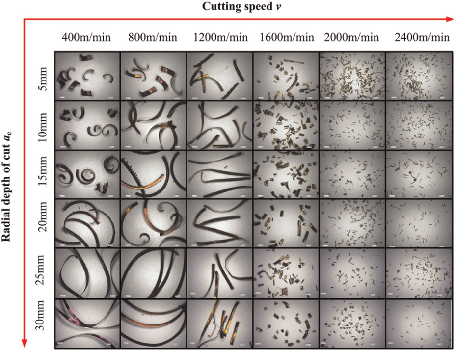
Chip morphologies obtained under different combinations of cutting parameters.
Magnified images of typical chip morphologies obtained at different cutting speeds are shown in Figure 3. Figure 3 shows that serrated chip appeared at the cutting speed of 400 m/min. The serrated chip was divided into separated segments at the cutting speeds of 2000 and 2400 m/min. Taking the formation of individual saw-tooth into consideration, it can be deduced that the tool–chip contact length became very small as the cutting speed surpassed 2000 m/min.
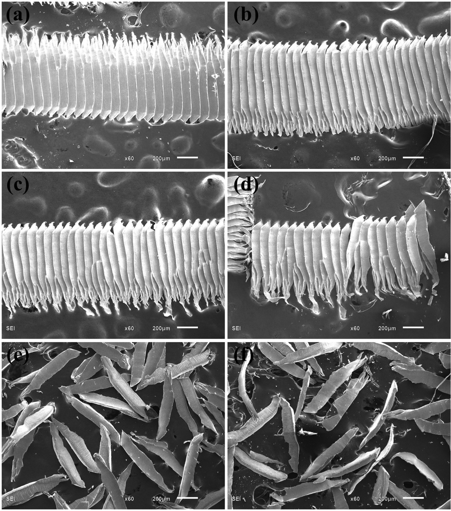
Magnified images of typical chip morphologies obtained at different cutting speeds (ae = 20 mm, fz = 0.06 mm/z, ap = 0.4 mm): (a) v = 400 m/min, (b) v = 800 m/min, (c) v = 1200 m/min, (d) v = 1600 m/min, (e) v = 2000 m/min and (f) v = 2400 m/min.
Figure 4 shows the schematic of the serrated chip, which was divided into separated segments and magnified images of the individual saw-tooth. Two view directions a and b are defined, as shown in Figure 4(a). Chip ends 1 and 2 are also denoted in Figure 4(a). The image shown in Figure 4(b) was captured in view direction a. Figure 4(b) shows the free surface of the chip. It can be seen that the free surface was relatively smooth. Images shown in Figure 4(c)–(g) were obtained in view direction b. It can be seen from Figure 4(d)–(g) that compared with chip end 1, chip end 2 exhibited the characteristics of irregular edge. Sphere-like workpiece material appeared near chip end 2. The sphere-like material and the blue color of chip end 2 indicated that the temperature at chip end 2 was higher than that at end 1 during the formation process of individual saw-tooth. The higher temperature can be attributed to the fierce plastic deformation and friction between the chip and cutting tool. It can be seen from Figure 4(f) and (g) that the softening effects caused by the high temperature at chip end 2 were very important for the formation of individual saw-tooth. The softened workpiece material at chip end 2 was torn by the external loads, leading to the formation of individual saw-tooth. It has been discussed that there are two theories, namely adiabatic shear theory9,10 and cyclic crack theory,11,12 for the saw-tooth chip formation. The first one suggests that the saw-tooth chip is caused by repeated thermoplastic instability, which happened in the primary shear zone. It is believed that when the thermal softening induced by plastic work overcomes the work hardening of the material, repeated thermoplastic instability will happen. 26 The second one states that saw-tooth chip results from the periodic crack initiate on the free surface of workpiece. It seems that the adiabatic shear theory is more suitable for describing the formation of individual saw-tooth obtained in this work.
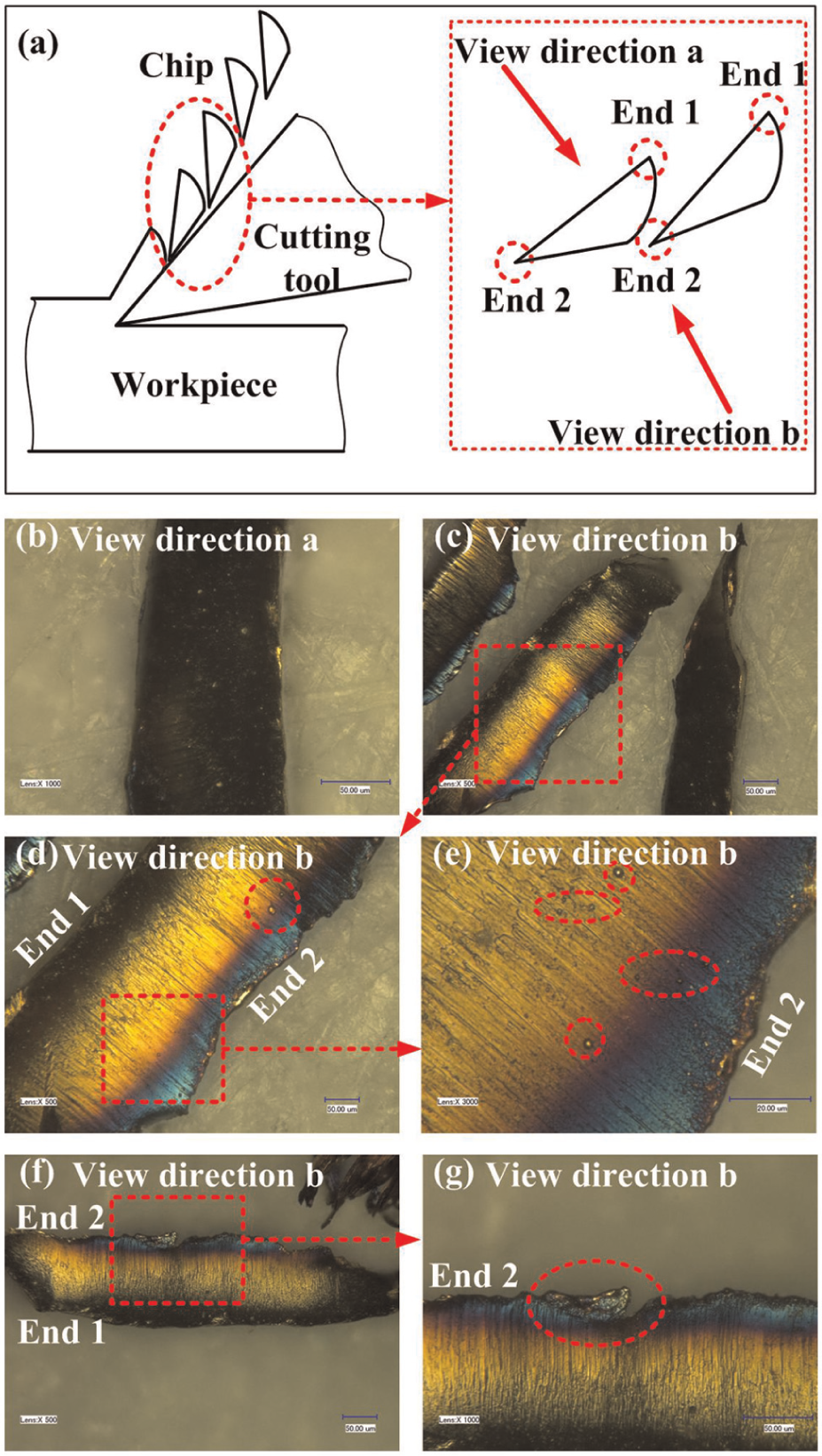
Schematic of the serrated chip, which was divided into separated segments and magnified images of the individual saw-tooth: (a) schematic of the serrated chip, (b) image obtained from view direction a, (c)image obtained from view direction b, (d) image obtained from view direction b, (e) image obtained from view direction b, (f) image obtained from view direction b and (g) image obtained from view direction b.
Figure 5 shows the line distribution of element O on the individual saw-tooth surface. Figure 5(b) indicates that the amount of element O was relatively large at chip ends 1 and 2. Moreover, there was larger amount of element O at chip end 2 than that at chip end 1. This was caused by the higher temperature at chip end 2. The higher temperature accelerated the chemical reaction between the workpiece material and oxygen from the air.
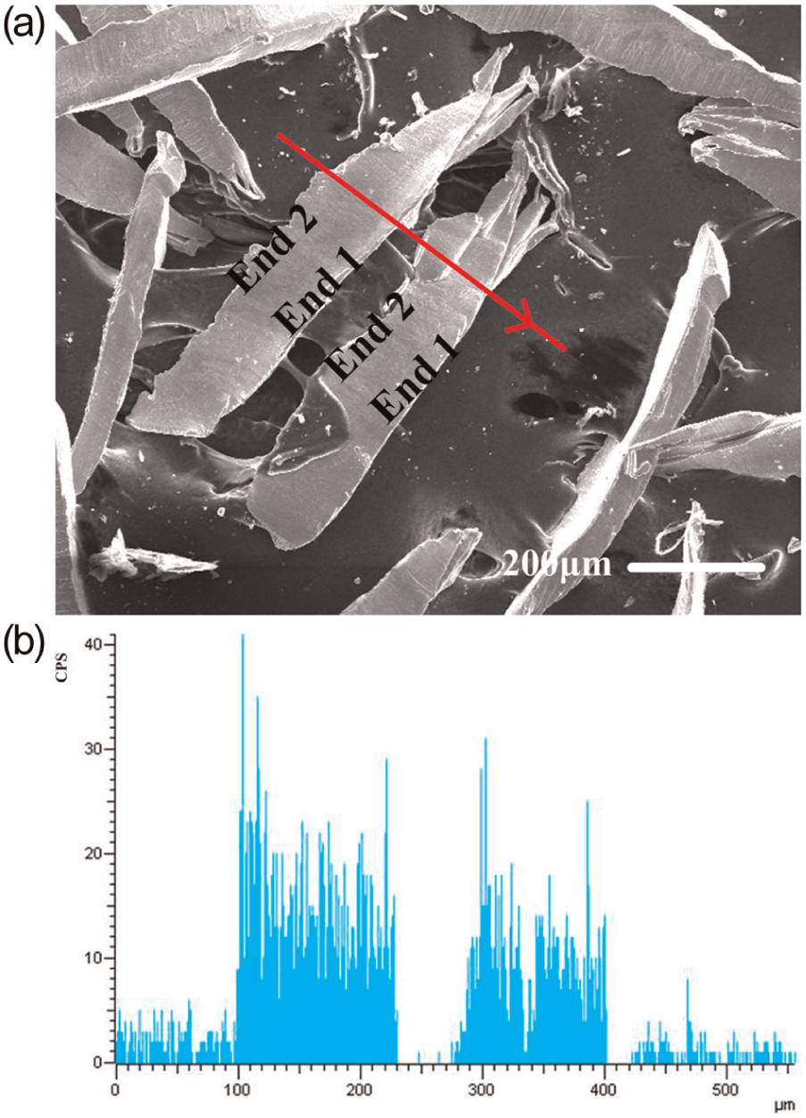
Line distribution of element O on the chip surface: (a) the position where EDS line scan was conducted and (b) line distribution of element O.
Tool wear
Even though the time of cut is shorter, there is a possibility that larger volume of material is removed at a higher cutting speed. Taking this into account, the volume V of material removed instead of the time of cut was used in the present study to express the tool life. The fitted curved surface for tool lives obtained under different combinations of cutting parameters is shown in Figure 6. Figure 6 shows that tool life decreased as the cutting speed increased. It was found that tool life increased with increasing radial depth of cut at the cutting speed of 400 m/min. When the other cutting speeds were used, tool life increased first and then decreased as radial depth of cut increased.
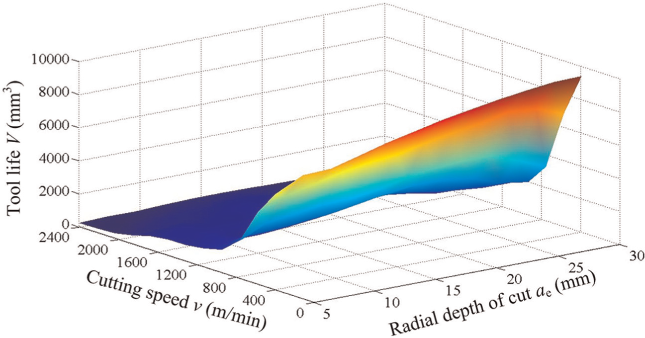
Fitted curved surface for tool lives obtained under different combinations of cutting parameters.
Tool lives obtained in the milling process were compared and analyzed for different combinations of cutting parameters. The analysis results showed that when different values of cutting speed were adopted, relatively long tool life was obtained at different values of radial depth of cut. The longest tool life can be obtained at the radial depth of cut of 30 mm when the cutting speed was 400 m/min. When the cutting speed was 2400 m/min, the longest tool life appeared at the radial depth of cut of 10 mm. Radial depth of cut at which relatively long tool life arose decreased as the cutting speed increased.
Considering the given cutting conditions, 10 and 25 mm were chosen to represent relatively small and large radial depth of cut, respectively. Analysis of tool life and tool wear mechanisms focused on the cutting tools tested at radial depth of cut of 10 and 25 mm. It can be seen from Figure 7(a) that when the cutting speed was below 1600 m/min, relatively long tool life can be obtained at relatively large radial depth of cut (25 mm). However, relatively long tool life arose at relatively small radial depth of cut (10 mm) as the cutting speed surpassed 1600 m/min.
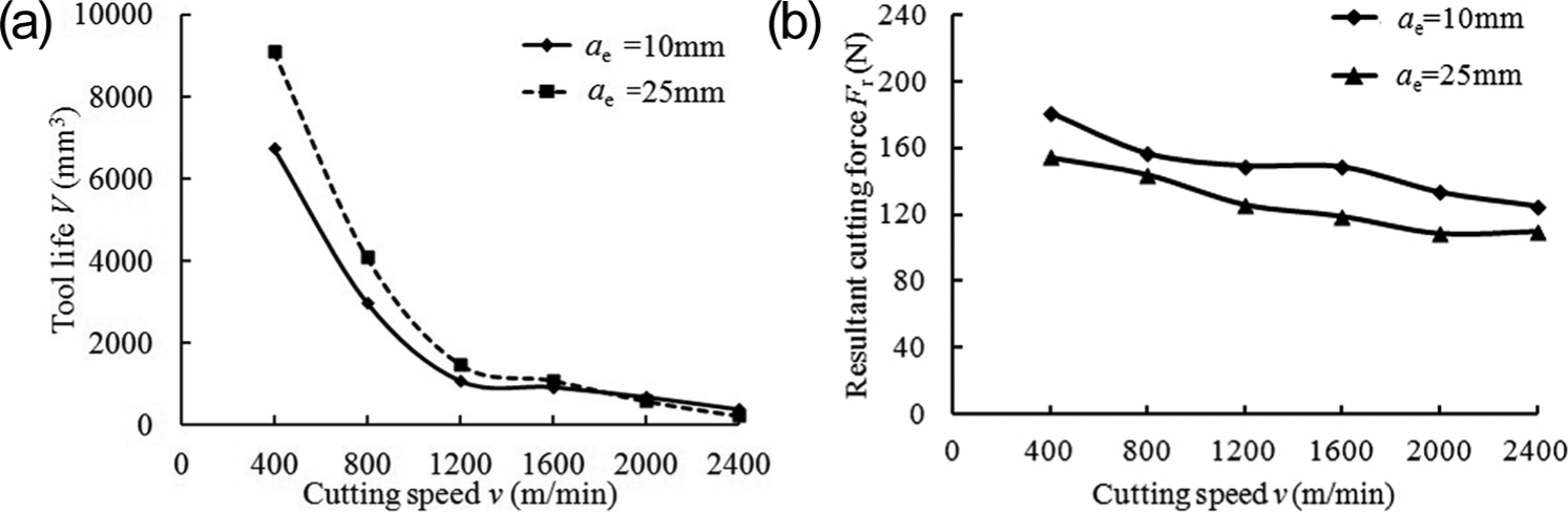
Tool life versus cutting speed and cutting forces versus cutting speed when the radial depth of cut ae were 10 and 25 mm: (a) tool life versus cutting speed and (b) cutting forces versus cutting speed.
In the milling process, cutting cycles consisted of cutting periods and non-cutting periods. For each test, three cutting periods were picked. The values of the resultant cutting forces were calculated from the recorded data points of cutting forces in different directions. Figure 7(b) shows the average values of the resultant cutting forces Fr obtained under different combinations of cutting parameters. It can be observed from Figure 7(b) that the cutting forces decreased with increasing cutting speed. The decreasing trends of cutting force were mainly caused by the softening effects induced by high cutting temperature. For each cutting speed, the cutting force obtained at the radial depth of cut of 10 mm was higher than that obtained at the radial depth of cut of 25 mm. In the present study, the milling cutter was positioned at the center line of the workpiece. The axial depth of cut and feed per tooth were fixed in this work. Taking these into account, Figure 8 shows the schematic of the milling process at relatively small and large values of radial depth of cut. Since the axial depth of cut was fixed, it can be inferred from Figure 8 that the average area of the chip cross section at the radial depth of cut of 10 mm was larger than that at the radial depth of cut of 25 mm. The calculated average value of the resultant cutting force was influenced greatly by the average area of the chip cross section. The larger average area of the chip cross section should be the main reason why the cutting force obtained at the radial depth of cut of 10 mm was higher for each cutting speed.
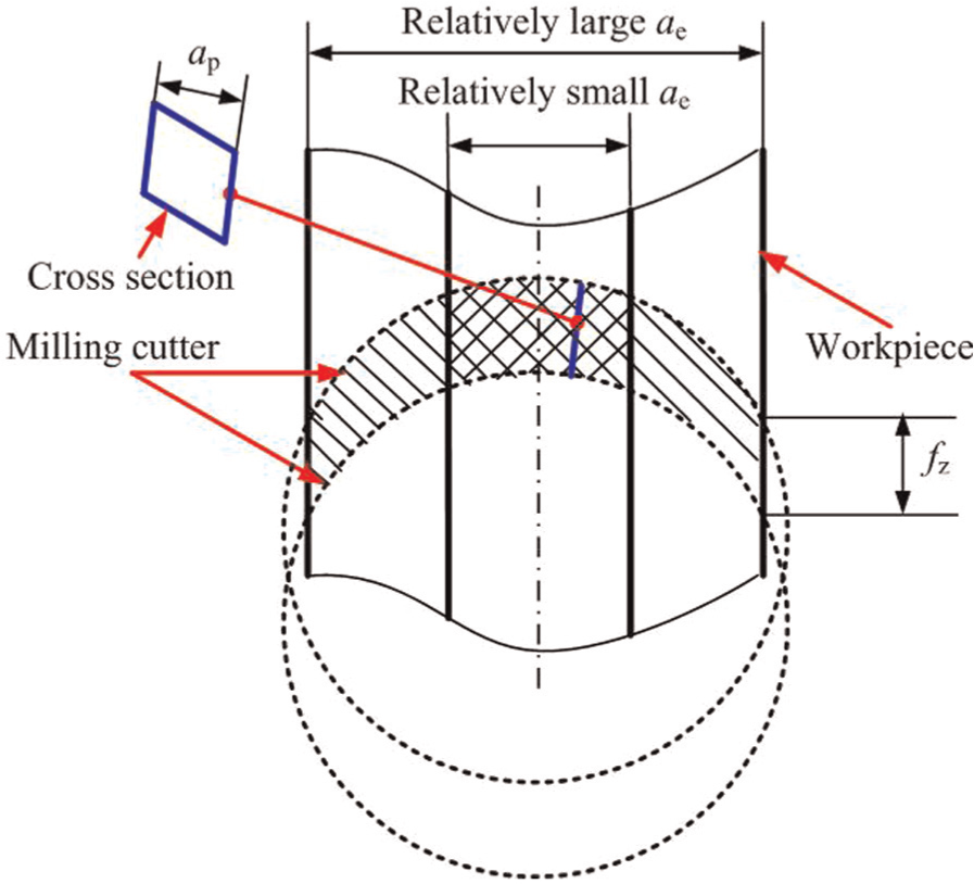
Schematic of the milling process at different values of radial depth of cut.
It can also be deduced from Figure 8 that the heating period (cutting period) at a relatively small radial depth of cut (10 mm) was shorter than that at a relatively large radial depth of cut (25 mm). Moreover, the cooling period (non-cutting period) was longer when a relatively small radial depth of cut was adopted. It can be deduced that when the same cutting speed was adopted, the cutting temperature arose at relatively small radial depth of cut (10 mm) was lower than that arose at relatively large radial depth of cut (25 mm). Taking the thermal softening effects into consideration, the higher cutting temperature at relatively large radial depth of cut (25 mm) also contributed the lower resultant cutting force to some extent.
The relatively low mechanical load should be the main reason why relatively long tool life arose at the radial depth of cut of 25 mm when the cutting speed was below 1600 m/min, as shown in Figure 7(a). When the cutting speed surpassed 1600 m/min, it seemed that the cutting temperature had greater effect on tool life than cutting force did. Due to the lower cutting temperature, longer tool life can be obtained at relatively small radial depth of cut (10 mm) as the cutting speed increased over 1600 m/min.
The analysis of tool wear mechanisms concentrated on cutting tools tested at relatively low (400 m/min) and high (2400 m/min) cutting speeds. When the cutting speed was 400 m/min and the radial depth of cut was 10 mm, SEM images of the typical worn tool can be obtained, as shown in Figure 9. It can be seen from Figure 9(a) and (b) that large flaked region and serious chipping appeared on the tool rake face and cutting edge, respectively. The appearance of large flaked region and serious chipping can be attributed to the relatively high mechanical load, as shown in Figure 7(b). Delamination of tool coatings and substrate can be clearly seen in Figure 9(d). Figure 9(a) and (c) indicates that fracture was the main wear mechanism of the tool flank face. EDS analysis of point 1 denoted in Figure 9(c) was performed. Large amount of elements W (47.88 wt%) from the tool substrate was found at point 1. The amount of element Fe was 17.62 wt%, indicating that adhesion also contributed to the tool flank wear to some extent.
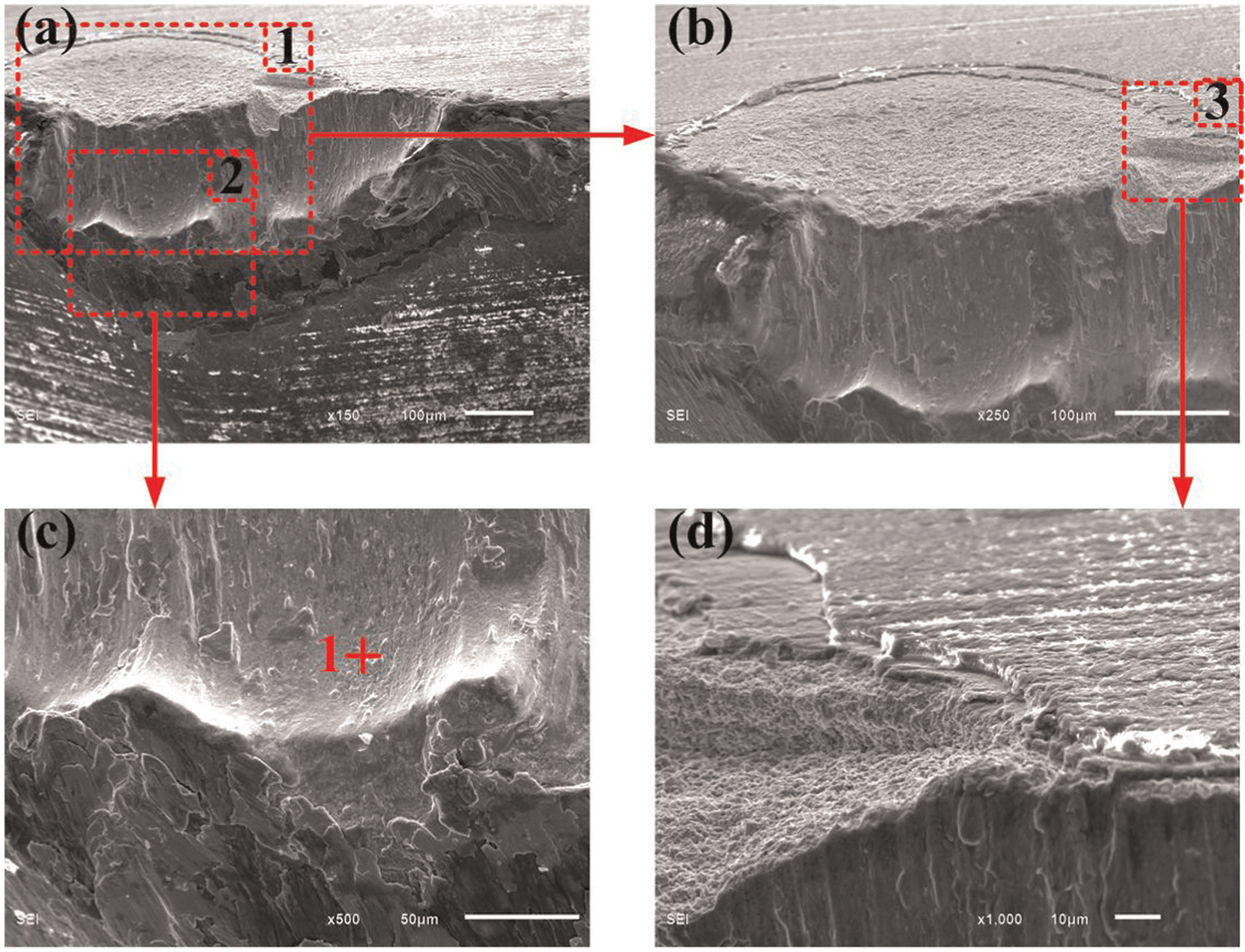
SEM images of the typical worn tool (v = 400 m/min, ae = 10 mm, ap = 0.4 mm, fz = 0.06 mm/z): (a) magnified image of the worn tool, (b) magnified image of region 1, (c) magnified image of region 2 and (d) magnified image of region 3.
Figure 10 shows the SEM images of the typical worn tool, which was obtained when the cutting speed was 400 m/min and the radial depth cut was 25 mm. It can be observed from Figure 10 that due to the relatively low cutting force shown in Figure 7(b), there was no flaked region on the tool rake face. However, chippings arose on the tool cutting edge. It can be deduced from the chip shown in Figure 10(b) and (d) that the fractured region acted as cutting edge during the milling process. Thermal crack perpendicular to the cutting edge was observed, as shown in Figure 10(c). This was not encountered when the radial depth of cut was 10 mm. It has been discussed that when the same cutting speed was adopted, higher cutting temperature arose at larger radial depth of cut. The appearance of thermal crack was mainly caused by the relatively high cutting temperature. It can be seen from Figure 10(b) and (d) that obvious scratches appeared on the tool flank face. It is inferred that abrasion affected the tool flank wear greatly. EDS analysis of point 2 in Figure 10(b) was conducted. The EDS analysis revealed large amount (46.33 wt%) of element Fe from the workpiece. The larger amount of element Fe at point 2 indicated that adhesion had greater effect on the tool flank wear at the radial depth of cut of 25 mm than it did when the radial depth of cut was 10 mm.
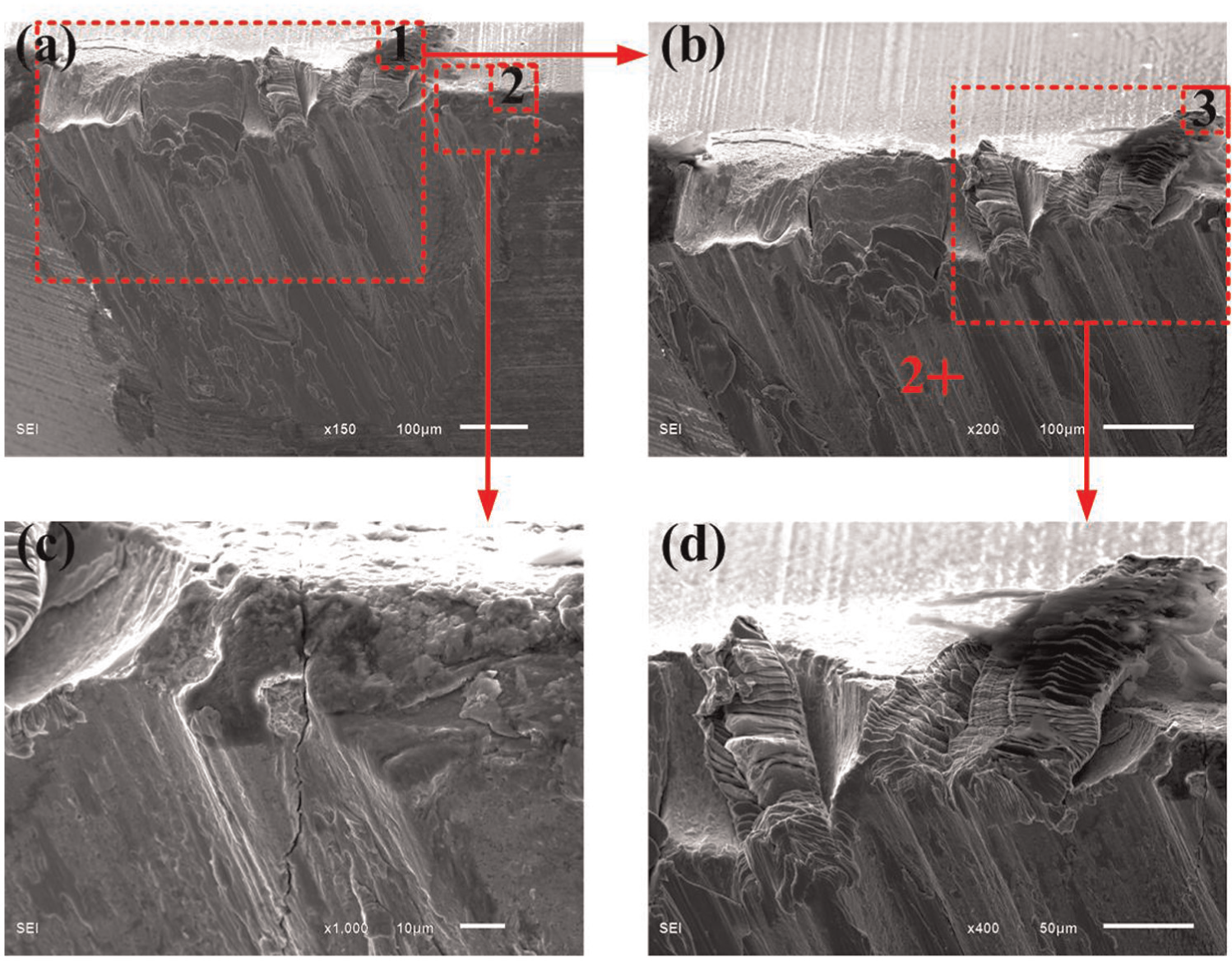
SEM images of the typical worn tool (v = 400 m/min, ae = 25 mm, ap = 0.4 mm, fz = 0.06 mm/z): (a) magnified image of the worn tool, (b) magnified image of region 1, (c) magnified image of region 2 and (d) magnified image of region 3.
Figure 11 shows the SEM images of the typical worn tool tested at cutting speed of 2400 m/min and radial depth of cut of 10 mm. Compared with the images shown in Figure 9 (v = 400 m/min, ae = 10 mm), there was no flaking on the tool rake face. This was mainly caused by the relatively low mechanical load shown in Figure 7(b). Coating delamination appeared near the cutting edge, as shown in Figure 11(b). The delaminated area was very small. This can be attributed to the drastically reduced tool–chip contact length, which has been discussed in section “Chip morphology.” The scratches shown in Figure 11(b) and (c) indicated the contribution of abrasion to the wear of tool flank face. It can be seen from Figure 11(c) and (d) that there was wing-like material adhered to the tool flank face. EDS analysis of point 3 in Figure 11(c) was performed. The analysis results revealed great amount of element Fe (79.82 wt%), indicating that adhesion had great effect on tool flank wear. Taking the EDS analysis results of point 1 in Figure 9(c) into account, it can be found that when the radial depth of cut was 10 mm, adhesion on the tool flank face became more serious as the cutting speed increased from 400 to 2400 m/min. This was mainly caused by the increased temperature induced by higher cutting speed.
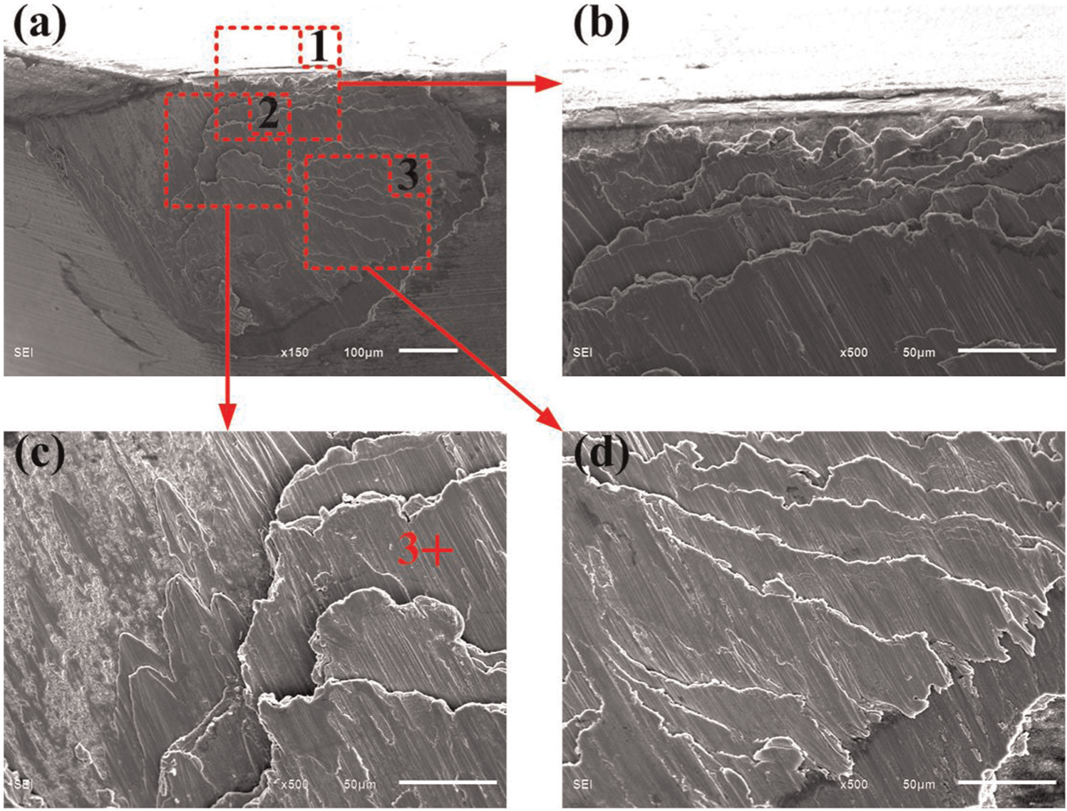
SEM images of the typical worn tool (v = 2400 m/min, ae = 10 mm, ap = 0.4 mm, fz = 0.06 mm/z): (a) magnified image of the worn tool, (b) magnified image of region 1, (c) magnified image of region 2 and (d) magnified image of region 3.
Figure 12 shows the SEM images of the typical worn tool obtained under the cutting parameter combination of v = 2400 m/min and ae = 25 mm. Compared with the images shown in Figure 10 (v = 400 m/min, ae = 25 mm) and Figure 11 (v = 2400 m/min, ae = 10 mm), it can be seen from Figure 12(a) and (b) that there was no chipping or coating delamination on the tool cutting edge. This was caused by the combined effects of the dramatically decreased tool–chip contact length and relatively low mechanical load, as shown in Figure 7(b). It can be seen from Figure 12(b) that due to the higher cutting temperature caused by larger radial depth of cut, there existed thermal crack perpendicular to the cutting edge. This phenomenon was not found in Figure 11 (v = 2400 m/min, ae = 10 mm) because of the relatively small value of radial depth of cut. It was found by Liu et al. 25 that rake face wear was one of the main tool wear patterns in ultra-high-speed (v = 1100 m/min) face milling of hardened steel. In this work, it can be seen from Figures 11 and 12 that there was no obvious rake face wear at the cutting speed of 2400 m/min. The tool–chip contact length decreased greatly due to the formation of individual saw-tooth, which arose at the cutting speed of 2000 m/min. It can be deduced that the new type of chip (individual saw-tooth) had great effect on the tool rake face wear as the cutting speed surpassed 2000 m/min.
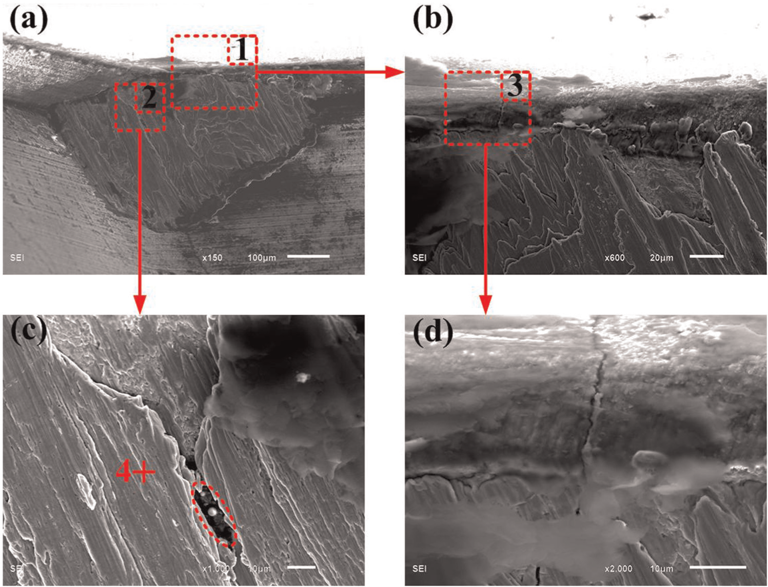
SEM images of the typical worn tool (v = 2400 m/min, ae = 25 mm, ap = 0.4 mm, fz = 0.06 mm/z): (a) magnified image of the worn tool, (b) magnified image of region 1, (c) magnified image of region 2 and (d) magnified image of region 3.
It can be observed from Figure 12(c) that there was sphere-like workpiece material on the tool flank face. The sphere-like material also reflected the high cutting temperature in the cutting process. It can be inferred from the scratches shown in Figure 12(b) and (c) that abrasion happened on the tool flank face. EDS analysis of point 4 denoted in Figure 12(c) showed that there were large amount (82.81 wt%) of element Fe at point 4. Considering the analysis results of point 2 in Figure 10(b), it can be concluded that when the radial depth of cut was 25 mm, the amount of element Fe on the tool flank face became much larger as the cutting speed increased from 400 to 2400 m/min.
Conclusion
High-speed face milling of hardened steel was conducted to investigate the effects of cutting parameters on chip morphology, tool wear and surface roughness. Radial depth of cut used in the present study was in the range of 5 to 30 mm. For each radial depth of cut, cutting speeds ranging from 400 to 2400 m/min were adopted. The values of 10 and 25 mm were chosen to represent relatively small and large radial depth of cut, respectively. The analysis of tool wear mechanisms concentrated on cutting tools tested at relatively low (400 m/min) and high (2400 m/min) cutting speeds. The following conclusions can be drawn from this work:
The chip morphology evolved similarly as the cutting speed increased despite the difference of radial depth of cut. Considering the formation of individual saw-tooth, it can be inferred that the tool–chip contact length decreased substantially as the cutting speed surpassed 2000 m/min. Two view directions (a and b) and two chip ends (1 and 2) were defined for the individual saw-tooth. It was found that the free surface of the chip was relatively smooth. Chip end 2 exhibited the characteristics of irregular edge and the temperature at chip end 2 was higher than that at end 1 in the chip formation process. The higher temperature at chip end 2 accelerated the chemical reaction between the workpiece material and oxygen from the air. The adiabatic shear theory is more suitable for describing the formation of individual saw-tooth.
It was found that when the cutting speed was relatively low, relatively long tool life can be obtained at large radial depth of cut. However, when the cutting speed was relatively high, smaller radial depth of cut was beneficial for the acquisition of longer tool life. At most of the cutting speeds adopted, tool life increased first and then decreased as radial depth of cut increased. When the cutting speed was 400 m/min and the radial depth of cut was 10 mm, due to the relatively high mechanical load, large flaked region and serious chipping appeared on the tool rake face and cutting edge, respectively. Fracture was the main wear mechanism of the tool flank face. Due to the relatively low cutting force, there was no flaked region on the tool fake face under the cutting parameter combination of v = 400 m/min and ae = 25 mm. However, chippings arose on the tool cutting edge and relatively high cutting temperature led to thermal crack perpendicular to the cutting edge. At cutting speed of 2400 m/min and radial depth of cut of 10 mm, the area of coating delamination near the cutting edge was small. This can be attributed to the drastically reduced tool–chip contact length. Due to the combined effects of the dramatically decreased tool–chip contact length and relatively low mechanical load, there was no chipping or coating delamination on the tool cutting edge under the cutting parameter combination of v = 2400 m/min and ae = 25 mm. When the cutting speed was 2400 m/min and radial depth of cut was 25 mm, there also existed thermal crack perpendicular to the cutting edge. It was found that adhesion on the tool flank face became much more serious as the cutting speed increased from 400 to 2400 m/min.
Footnotes
Appendix 1
Declaration of conflicting interests
The authors declare that there is no conflict of interest.
Funding
This research is supported by the Doctor Foundation from Henan Polytechnic University (B2014-032), the National Natural Science Foundation of China (51175310) and the National Natural Science Foundation of China (51205112).