
Abstract
Torus cutters are increasingly used in machining high-hardness materials because of high processing efficiency. However, due to the large hardness variation in assembled hardened steel workpiece, the tool wear occurs easily in machining process. This severely affects the machined surface quality. Here, we conduct a research on the tool wear and the machined surface quality in milling assembled hardened steel mold with a torus cutter. The experimental results show the abrasive wear mechanism dominates the initial tool wear stage of the torus cutter. As the tool wear intensifies, the adhesive wear gradually occurs due to the effect of alternating stress and impact load. Thus, the mixing effect of the abrasive and adhesive wears further accelerates tool wear, resulting in occurrence of obvious crater wear band on the rake face and coating tearing area on the flank face. Finally, the cutter is damaged by the fatigue wear mechanism, reducing seriously the cutting performance. With increase of flank wear, moreover, there are increasingly obvious differences in both the surface morphology and the cutting force at the two sides of the joint seam of the assembled hardened steel parts, including larger height difference at the two sides of the joint seam and sudden change of cutting force, as a result, leading to decreasing cutting stability and deteriorating seriously machined surface quality.
Introduction
With the rapid development of automobile, aerospace, shipbuilding industries and so on, large-size molds are increasingly demanding, whose manufacturing level is directly reflected by the high-speed milling technology of hardened steel molds, and now, it has become the key technology for the research and development in the worldwide manufacturing industry of automobile molds.1–4 In machining hardened steel molds, the cutting tool deforms easily, and meanwhile, wear and damage will be accelerated. As a result, it is difficult to guarantee the dimension precision and surface quality of the machined workpiece, increasing the subsequent time for manual grinding. 5 Despite exhibiting good cutting performance of torus cutters in machining hardened steel molds, there are still prominent problems in tool life and machining quality. Especially large-size molds are generally assembled by hardened steel workpieces, and thus, there is a large hardness difference between them, making the subsequent semi-finish and finish machining processes more complicated, thus further increasing machining difficulty. Therefore, it is imperative to study the cutting performance of torus cutters in machining assembled hardened steel workpieces.
In order to improve the surface quality and tool life in milling hardened steel, Machado and Diniz 6 analyzed the tool wear mechanisms during continuous and interrupted machining of hardened steel. Aramcharoen et al. 7 conducted evaluation of the cutting performance in milling hardened steel using the cutting tools with different coatings and found better performance in the TiN coating ball-end cutter. Wu et al. carried out research on the tool wear mechanism of corner milling in the deep cavity of the hardened steel mold. The results showed that with decrease of the corner radius, the tool wear mechanism changed and tool wear rate accelerated. 8 Isabela and Diniz 9 conducted an experiment of milling AISI D6 hardened steel and obtained the effect laws of the tool path and inclination on the tool life and surface quality. Scandiffio et al. 10 analyzed influence of the toolpath direction and tool–workpiece surface contact on machining forces, surface roughness and tool life in machining hardened steel. Magalhaes and Ferreira 11 conducted an experiment of milling the hardened steel H13 and obtained the effect of tool path and cutting parameters on machining efficiency, surface roughness and machining accuracy. Batista et al. 12 established a mathematical model of surface roughness produced by high-speed machining with ball-nose end mill. Vivancos et al. 13 and Begic-Hajdarevic et al. 14 studied the surface roughness produced in high-speed side milling of hardened steels and obtained influence laws of cutting parameters on surface roughness. Neto et al. 15 investigated experimentally the curved surface milling of hardened steel and found that decrease of radial force can improve the surface quality and tool life. Huang et al. 16 analyzed the surface integrity and fatigue performance in milling hardened steel AISI D2 at different speeds. Nicola et al. 17 studied the effect of different milling paths on the surface morphology of H13 hardened steel. Cheng et al. 18 performed an experiment of milling steel 508III and achieved interactions of tool wear and milling temperature with each other. Cui et al. studied experimentally the impact of cutting parameters on chips morphology and cutting tool life in high-speed milling of hardened steel. It was found that a minor radial cutting depth helped in prolonging the tool life, and the tool–chip contact length decreased obviously when the milling speed was over 200 m/min. 19
To sum up, the current related research studies mainly focus on the cutting mechanism and surface quality in milling single-hardness hardened steel materials. However, fewer research studies target machining multi-hardness assembled hardened steel, and moreover, only ball-end cutters are used.20,21 Here, we conduct research on the tool wear and machined surface quality in milling assembled hardened steel mold with torus cutters. The results may not only provide theoretical and technological support but also promote application of torus cutters.
Experimental design
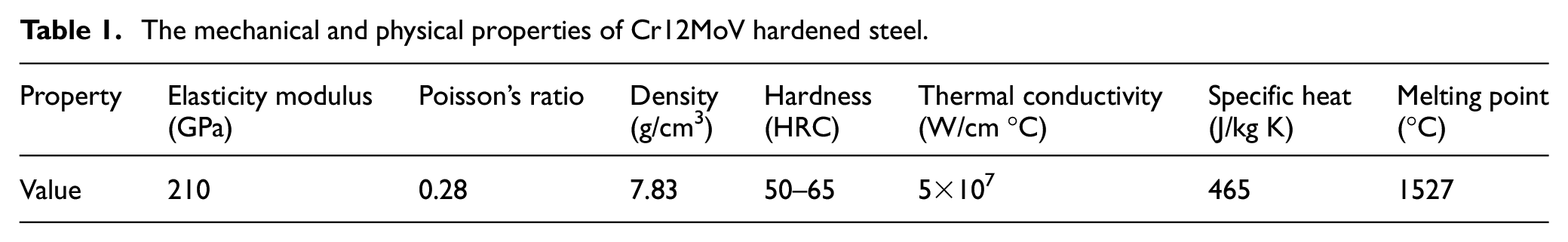
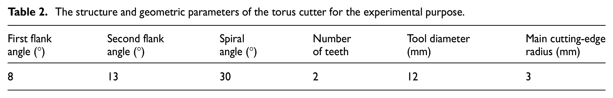
In order to analyze the cutting forces, surface quality and tool wear characteristics in milling multi-hardness assembled hardened steel, a corresponding high-speed milling experiment is designed in this article. It is carried out on the VDL-1000E milling center, and the fixed experimental system is shown in Figure 1. Cr12MoV assembled hardened steel is chosen as the experimental workpiece, and it is assembled by two different hardness (51HRC and 61HRC) blocks with the same size. That is, their lengths are both 100 mm, width 60 mm and height 80 mm. The fixture and assembled workpiece are connected together by bolts before the experiment, as shown in Figure 2(a). Table 1 shows the mechanical and physical properties of Cr12MoV hardened steel. The self-made torus cutter is used in the experiment, in which the tool bar is Kenner K88UF ultrafine-grained cemented carbide, and it is physically coated with TiSiN, as shown in Figure 2(b). Table 2 shows the main structure and geometric parameters of the torus cutter.
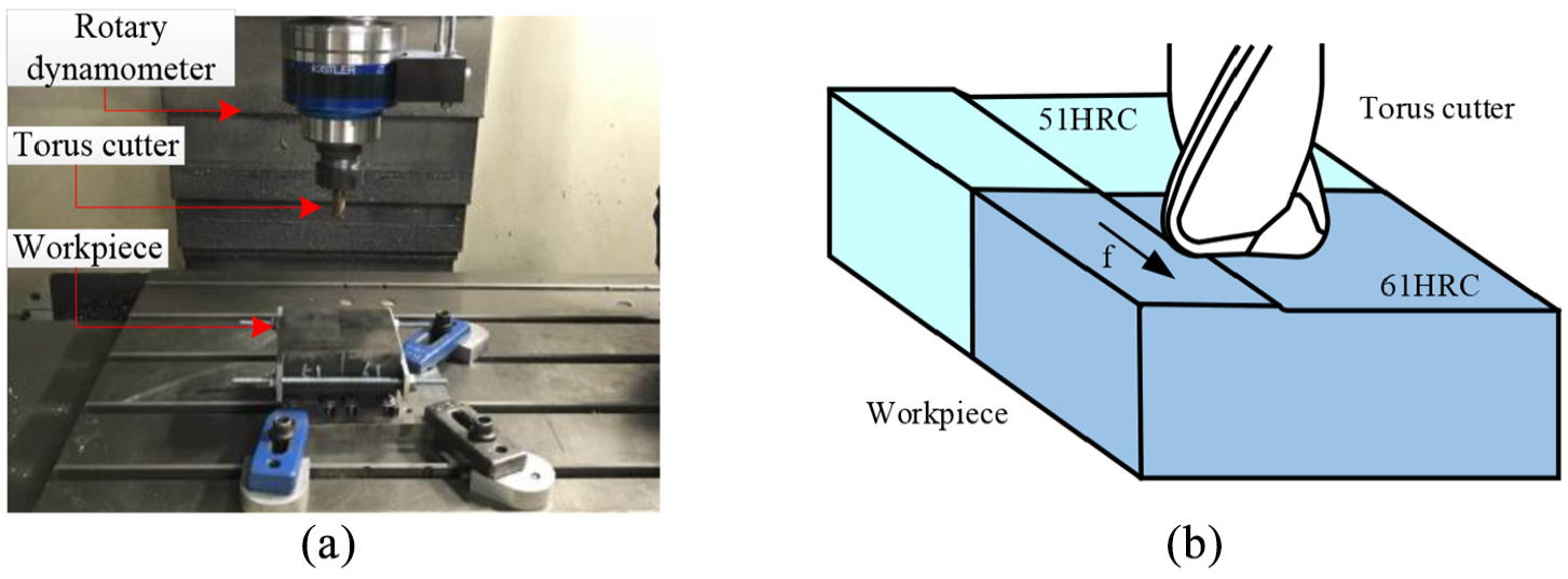
The experimental system. (a) The experimental site. (b) Cutting state.
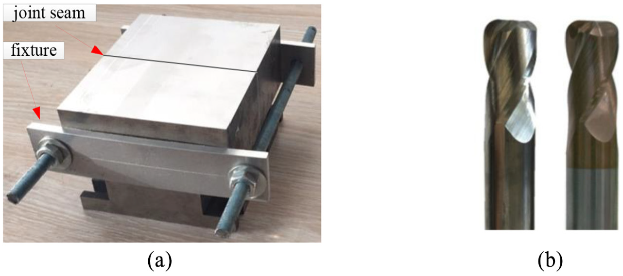
The experimental cutter and workpiece. (a) The experimental workpiece. (b) The torus cutter.
The mechanical and physical properties of Cr12MoV hardened steel.
The structure and geometric parameters of the torus cutter for the experimental purpose.
In the experiment, when the cutting direction is perpendicular to the joint seam and is from the low-hardness part to the high-hardness one in the workpiece, the cutting parameters are kept invariable, and the detail parameters are the cutting speed 150 m/min, the feed per tooth 0.15 mm, the cutting width 0.4 mm and the axial cutting depth 0.2 mm. In order to observe influence of the tool wear on machined surface quality, the cutter and workpiece are removed off every 5 min and the experiment ends once obvious breakage occurs on the blade. There, VHX-1000 super-high magnification zoom lens microscope and SU3500 scanning electron microscope are used to detect the tool wear morphology, and Taylor CCI profilometer is used to measure the surface morphology of the machined workpiece. The cutting force data are measured by a Kistler 9171A rotary dynamometer (Fx, Fy and Fz range from −10 to 10 kN, sensitivity of Fx and Fz are −8.1pC/N, Fy −4.1pC/N, and linearity ≤±0.5% FSO). In addition, we detect the surface morphology difference at both sides of the joint seam also, in which the 0.4 mm*0.4 mm area at each side of the joint seam is chosen for detection. The profilometer Taylor CCI is used to take sections of the selected areas perpendicular to the joint seam. Then, the maximum height difference of the two sides adjacent to the joint seam can be obtained through measuring the taken sections. Figure 3 shows the white light interferometer measures the surface morphology of the joint seam area and the maximum contour height (Sz) of the sampling areas at both sides of the joint seam.

The surface morphology and the maximum contour height Sz measured by the white light interferometer. (a) The surface morphology of the joint seam. (b) Sz of the two sides adjacent to the joint seam.
Results and discussion
Wear process and wear morphology of torus cutter
Figure 4 shows the rake wear morphology changes of the torus cutter in different cutting times. Figure 4(a) shows the new cutting edge of the torus cutter coated with TiSiN. When the cutting time is 20 min, the cutting edge is worn, and thus, a small-width wear band comes into being on it, as shown in Figure 4(b). As further cutting proceeds, the wear band becomes gradually wider. For 40 min, some tiny gaps occur on the cutting edge, and the coating around the gaps slightly peels off, and here, the substrate material is slightly exposed on the rake face, as shown in Figure 4(c). When the cutting time is more than 60 min, obvious crater wear appears on the rake face close to the cutting edge, and then, the crater constantly widens, as shown in Figure 4(d). Meanwhile, the gaps on the cutting edge gradually increase in number and size, and here, the coating obviously peels off. When the cutting time is 100 min, the continuous impact load causes obvious cracks and massive coating shedding off the gaps on the cutting edge, as shown in Figure 4(f). Especially, when the cutting time increases to 140 min, the serious chip and plastic deformation appear at contact area between the cutting edge and workpiece, further resulting in the breakage of the rake wear area, and finally, the cutter cannot work any longer, as shown in Figure 4(h).
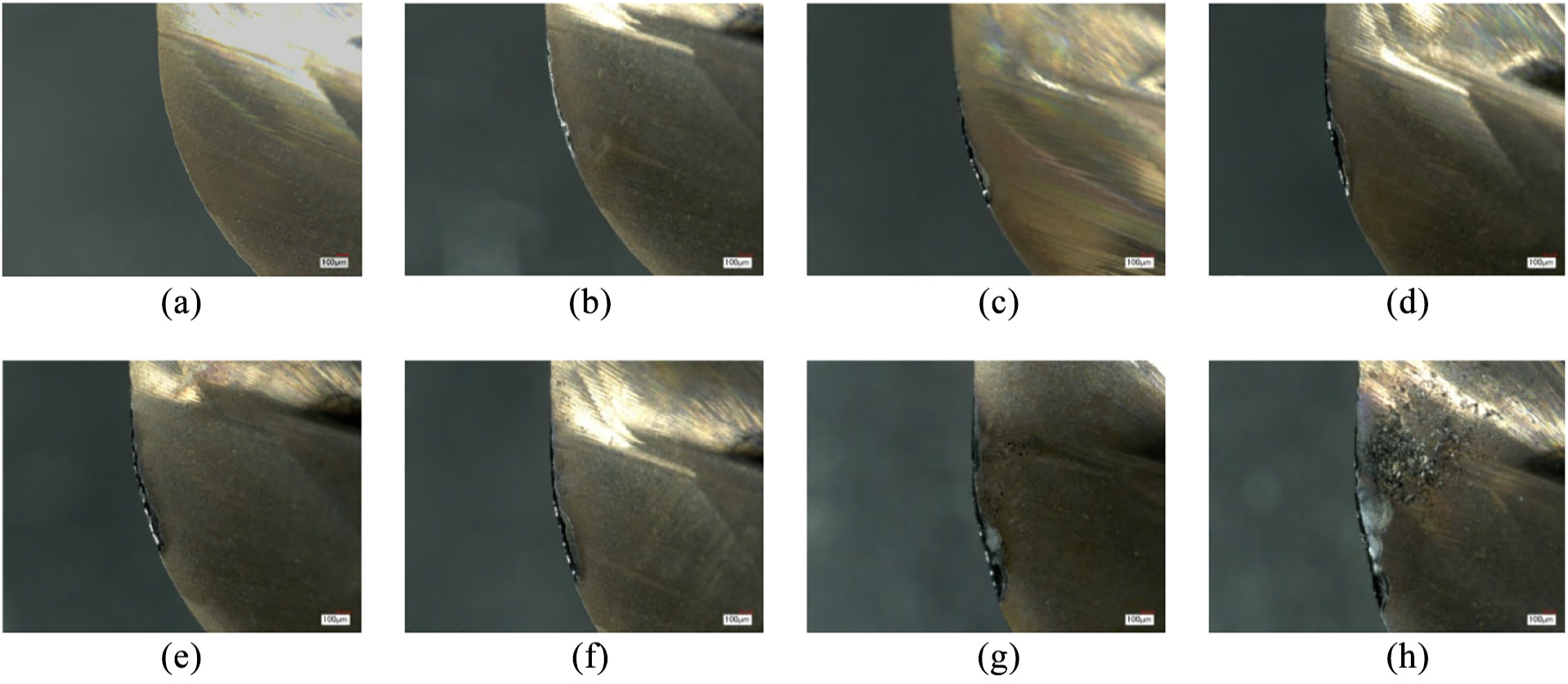
The rake wear morphology of the torus cutter. (a) T = 0 min. (b) T = 20 min. (c) T = 40 min. (d) T = 60 min. (e) T = 80 min. (f) T = 100 min. (g) T = 120 min. (h) T = 140 min.
According to the flank wear morphology of the torus cutter in Figure 5, as the cutting goes on, the flank wear area increases gradually, and the serious wear area mostly concentrates on the junction between the arc part and flat one on the cutting edge. When the cutting time is 40 min, a slight wear area appears on the flank face, including some tiny and dense uniform wear stripes (see Figure 5(c)). The phenomena can be attributed to the discrete shedding of coating by scraping. As the cutting time is 60 min, the wear band gradually becomes triangular, and here, a part of the substrate material falls off in the middle range of the wear band. The initial gap has formed on the cutting edge, and the flank wear VB reaches 0.08 mm, as shown in Figure 5(d). With increasing aggravation of the tool wear, when the cutting time increases to 100 min, the strong alternate action of the thermodynamic load weakens the adhesiveness between the substrate and coating on the flank face. Thus, the scraping area enlarges obviously, which is accompanied by quick peeling-off of the coating and substrate material, and the flank wear VB attains 0.14 mm, as shown in Figure 5(f). When the cutting time is 140 min, finally, the tool substrate weakens obviously, and subsequently, the cutting edge breaks seriously, as shown in Figure 5(h).
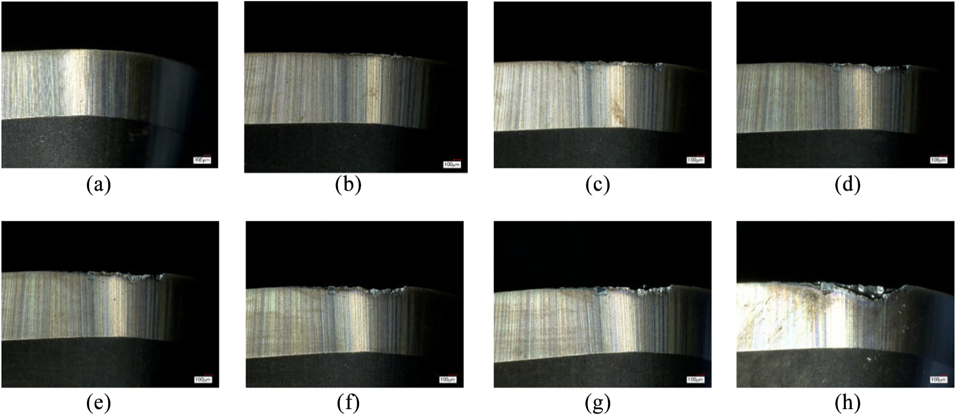
The flank wear morphology of the torus cutter. (a) T = 0 min. (b) T = 20 min. (c) T = 40 min. (d) T = 60 min. (e) T = 80 min. (f) T = 100 min. (g) T = 120 min. (h) T = 140 min.
Effect of torus cutter wear on cutting forces
Figure 6 shows variation of the tangential cutting force and radial cutting force of the torus cutter when the flank wear is 0.08 mm. It can be seen from the figure that the tangential cutting force changes obviously at the two sides of the joint seam, and the cutting force produced by milling the high-hardness component is relatively larger. By contrast, the radial cutting force increases slightly in cutting the high-hardness component. Moreover, the instantaneous peak of the cutting force appears obviously due to the impact effect when the cutter passed through the joint seam.
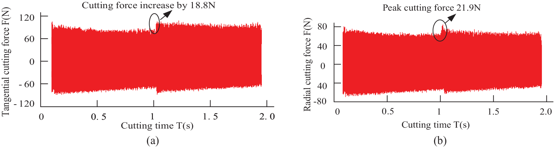
Variation of cutting forces when the flank wear was 0.08 mm. (a) Tangential cutting force. (b) Radial cutting force.
It can be seen from Figure 7 that how the flank wear of the torus cutter affects the cutting forces. As the flank wear VB is 0.08 mm, the tangential cutting force at the two sides of the joint seam increases slightly, only by 18.8 N. However, when the flank wear VB reaches 0.21 mm, the tangential cutting force increases to 55.3 N. Similarly, with the development of the tool wear, the instantaneous peak of the radial cutting force also obviously increases, and the peak value is up to 42.8 N when the flank wear VB is 0.21 mm. The reason for the above is as follows: as the cutting edge of the torus cutter gets blunt, the negative rake angle cutting occurs, further aggravating the impact of the cutter on the joint seam area. Here, the growing extrusion and friction between the flank face and workpiece surface obviously increase the tangential cutting force and the instantaneous peak of the radial cutting force at the joint seam. This makes the entire cutting process more complex.
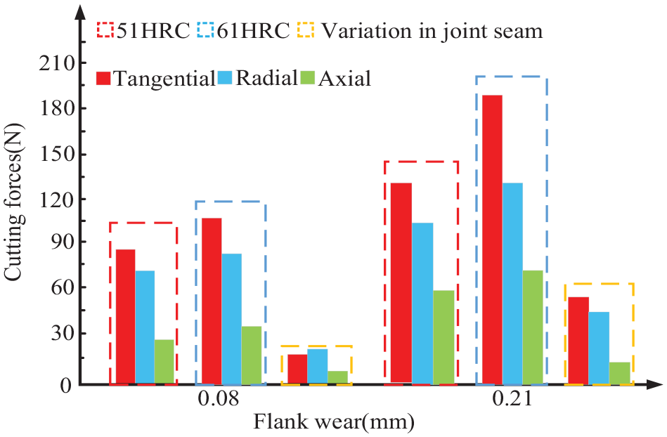
Influence of the flank wear on cutting forces.
Analysis of the torus cutter wear mechanism
Figure 8(a) shows the cutting edge micro-morphology of the torus cutter for 40 min of cutting. The coating shedding and the substrate wear traces in the cutting edge wear area can be clearly observed from the figure. Figure 8(b) is the local enlarged figure of Area A in Figure 8(a). It can be observed from Figure 8(b) that there are uniform striped wear traces on the flank face close to the cutting edge, which forms an obvious wear band in the direction of the relative sliding and scraping between the tool and workpiece. That is because a large cutting force load is produced during cutting assembled hardened steel workpiece with the torus cutter. When the cutting edge contacts with the workpiece, the impact and extrusion of hard particles in the workpiece material weaken the adhesive force among carbide particles of the cutter. Thus, the carbide particles are gradually ground off, forming an obvious abrasive wear area, as shown in Figure 8(c).
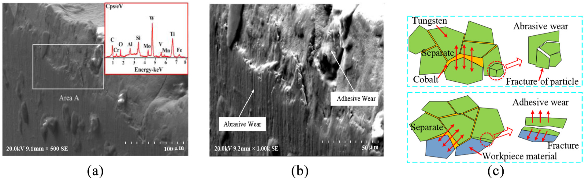
The micro-morphology of the cutting edge for 40 min of cutting. (a) The wear micro-morphology of cutting edge.(b) Magnified Area A. (c) Wear mechanism analysis.
The energy dispersive spectrometer is used to further analyze the torus cutter wear. We observe that the elements such as Cr, Mo, V, Fe, Mn and so on in the workpiece have already appeared on the flank face. This is because the stress load between the cutter and workpiece material gradually increases with aggravation of tool wear, further strengthening adhesive action between the cutter and workpiece material and finally causing the adhesive effect of the cutter and chips. It can be seen from Figure 8(c) that as the adhesive material near the cutting edge constantly increases, the chips produced in the subsequent milling increase impact load when they flow through the cutting edge, and thus, the chip material adhesive to the cutter gradually strips off and takes the substrate material off the cutting tool. As a result, some coating tearing area forms on the cutter.
Figure 9(a) shows the cutting edge micro-morphology of the torus cutter for 120 min of cutting, in which a wide-range breakage area appears on the cutting edge. Figure 9(b) clearly shows the complex fracture morphology on the cutting edge as well as the obvious tearing and chip accumulation near the fracture surface. The reason for the above is as follows. As the flank wear aggravates, the stress load on the cutting edge gradually increases, and especially the interactive effect of cyclical impact and vibration on the cutting edge makes the crystal faces of the cutter substrate particles separate from each other. As the gaps among particles grow, the minimal cracks gradually form on the cutting edge. Then, the cracks are further expanded by load impact, causing fracture of local material on the cutting edge, as shown in Figure 9(c).
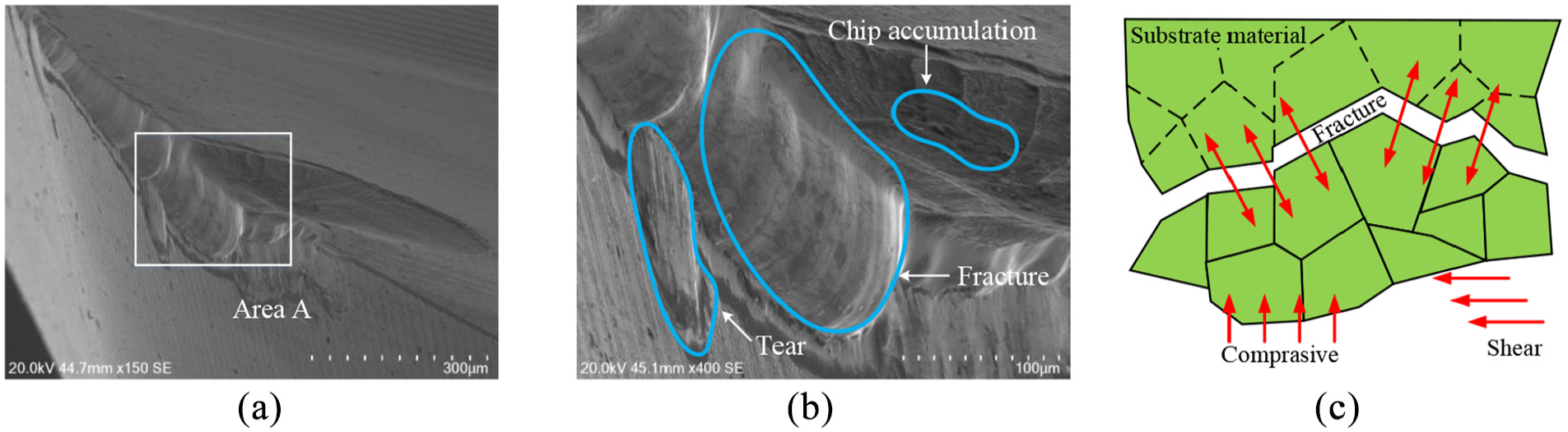
The cutting edge micro-morphology for 120 min of cutting. (a) The breakage morphology of the cutting edge.(b) Magnified Area A. (c) Wear mechanism analysis.
Effect of tool wear on the surface quality of assembled hardened steel workpiece
Figure 10 shows the three-dimensional (3D) surface morphology of different cutting areas in machining multi-hardness assembled hardened steel workpiece without wearing. It can be obtained from the figure that the surface morphology at the two sides of the joint seam shows significant difference, while the one away from the joint seam slightly changes. In addition, in the area away from the joint seam, the surface quality in the high-hardness area is much worse than the one in the low-hardness area.
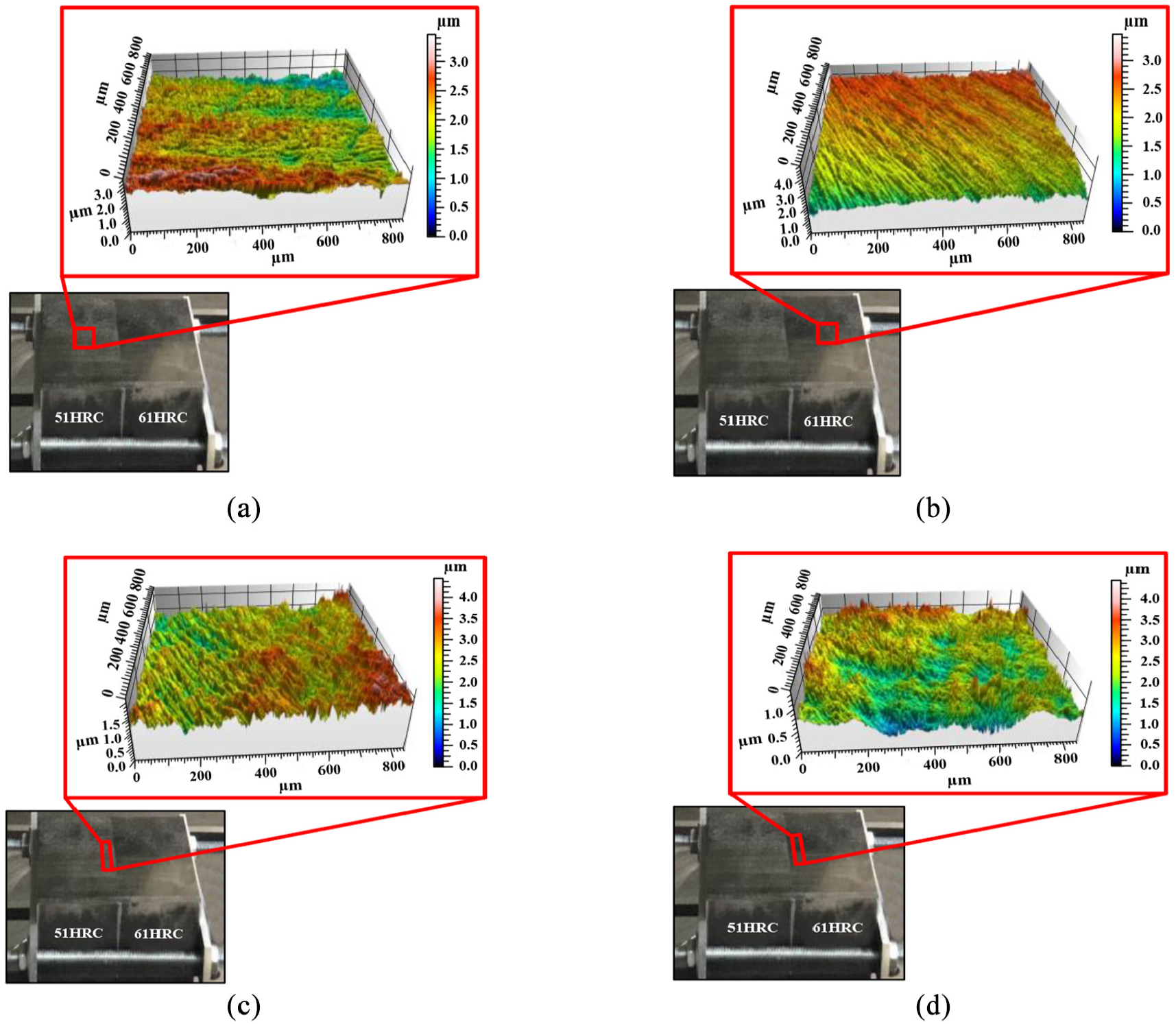
The surface morphology of workpiece with the cutter being unworn. (a) 51HRC area. (b) 61HRC area. (c) 51HRC side of the joint seam. (d) 61HRC side of the joint seam.
Table 3 shows variation of the height difference between the two sides of the joint seam in different flank wear states. It is found from this table that in machining multi-hardness assembled hardened steel workpiece, the surface morphology distinction between the two sides of the joint seam is reflected as a height difference on the vertical plane. However, with aggravation of the tool wear, the height difference gradually increases, and especially when the flank wear VB is 0.21 mm, the height difference is even more than 2.1 μm. Due to the effect of the impact force at the joint seam as well as the different cutting resistance from different-hardness parts, the scraping and skidding occur at the joint seam, resulting in undercutting or overcutting, finally causing a height difference at the joint seam. As the tool wear further aggravates, the cutting state at the joint seam becomes particularly complex, and the height difference between the two sides of the joint seam gets increasingly obvious.
Variation of the height difference between the two sides of the joint seam in different flank wear states.
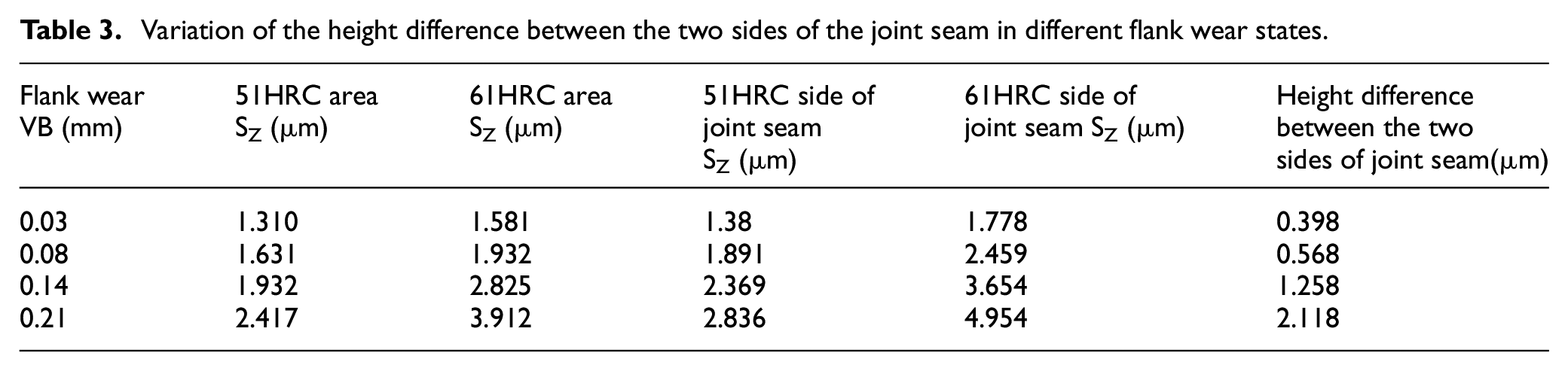
Figure 11 describes the cutting states of different cutting areas in milling the assembled hardened steel workpiece with the torus cutter. In cutting from the low- to high-hardness part, the sudden enlargement of workpiece hardness instantaneously increases the tangential resistance against the cutter, finally producing a strong impact load. On one hand, the tool wear is accelerated; on the other hand, the impact scratches occur on the brittle workpiece surface, which decreases the machining quality at both sides of the joint seam. Besides, the friction between the flank face and high-hardness part gradually enlarges, resulting in stronger plowing force between the cutter and workpiece as well as change in the micro-texture of workpiece surface under the rapid increase of thermal load. Finally, the interactions of the strong plowing force and surface micro-texture change cause more complex surface morphology at the two sides of the joint seam.
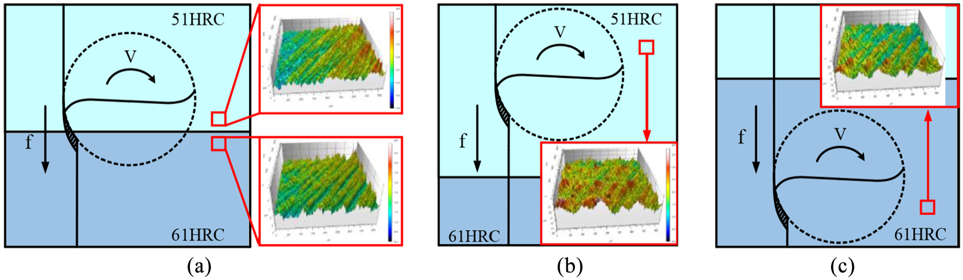
The cutting states in different-hardness areas. (a) The cutting state at the joint seam. (b) The cutting state in 51HRC area. (c) The cutting state in 61HRC area.
Conclusion
When the torus cutter is used to machine the assembled hardened steel workpiece, there is more complex dynamic impact load, leading to the obvious increase of tangential force and the instantaneous change of radial force occurring at the both sides of the joint seam, further increasing the cutting instability.
Under the interactions of the abrasive and adhesive wear mechanisms, the tool wear initially occurs on the cutting edge and then gradually extends to the rake face and flank face, and finally, obvious crater wear band and coating tearing area form on both faces.
As the tool wear further aggravates, the torus cutter gradually turns into the breakage stage dominated by fatigue wear mechanism under the action of strong thermal load. Here, the extensive coating and substrate material peel off from the cutter.
The machined surface quality of the torus cutter in milling multi-hardness assembled hardened steel is obviously influenced by the tool wear. As the flank wear worsens, the strong plowing force and surface micro-texture change cause more complicated surface morphology at both sides of the joint seam.
Footnotes
Declaration of conflicting interests
The author(s) declared no potential conflicts of interest with respect to the research, authorship, and/or publication of this article.
Funding
The author(s) disclosed receipt of the following financial support for the research, authorship, and/or publication of this article: The authors would like to acknowledge the support of the National Natural Science Foundation of China (Grant No. 51975168) and the Natural Science Foundation of Heilongjiang Province (Grant No. E2016047).