
Abstract
Single-point incremental forming is a sheet metal forming technique with great potential for use in prototyping and custom manufacture. While this process has undergone considerable development in recent years, designers may benefit from clear design rules to guide the process of designing for and implementing single-point incremental forming. This article presents simple design guidelines that translate forming limits into simple design constraints. A method of developing intermediate models for multi-pass forming is also documented. To demonstrate the utility of such simple design rules, examples of components that were made using this process are presented as case studies.
Introduction
Single-point incremental forming (SPIF) is a flexible sheet metal forming technique wherein parts are formed by the motion of a small tool moving in a series of passes around the outer periphery of the sheet. SPIF is part of a broad class of sheet metal forming techniques referred to as asymmetrical incremental sheet forming, which are described by Jeswiet et al. 1 and Hagan and Jeswiet. 2 The configuration of SPIF, outlined in Figure 1, is particularly attractive as it is easily implemented in a conventional machining centre with little modification, allowing it to be easily adopted by existing machine shops. A further advantage of SPIF is that the implementation inside a computer numerical control (CNC) mill allows conventional machining operations to be performed on the part in addition to forming operations.
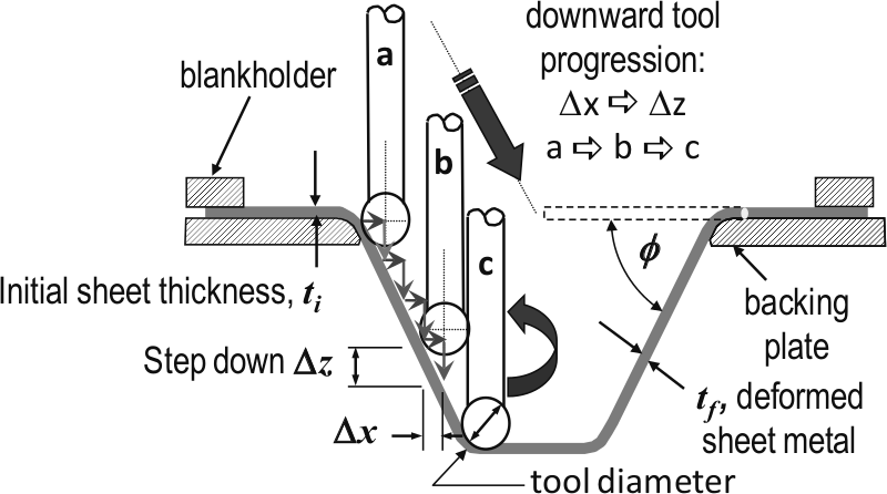
Configuration of SPIF.
While there has been much discussion of SPIF as a useful custom manufacturing process, only a small number of end-user ready applications have been documented. Some of the prototypes made by SPIF have included a solar cooker, 3 automotive components, 1 a patient-specific ankle support 4 and a cranial implant. 5
For any process to be widely adopted, one must be able to clearly communicate to the end-users the capabilities and limitations. To achieve this, simple design rules are presented that clearly communicate the geometrical constraints of SPIF. These rules were then used to successfully make a series of components for a variety of customers.
Much research has been done to characterize the forming limits of SPIF to determine ahead of time if a part can be successfully formed. Most often the characterization of forming limits is done by developing forming limit curves,6–8 which can then be used in finite element simulations to determine prior to forming if a part exceeds the maximum permissible strain.
For some time, it has been known that much larger strains can be achieved than in conventional sheet forming.9–14 For this reason, it has been suggested that SPIF uses the fracture forming limit curve (FFLC) to represent forming limits rather than a conventional forming limit curve. The cause of this increase in formability is the issue of some debate, with some authors claiming it is due to through-thickness shear,15,16 while others claim that it is due to localization of strain around the forming area, resulting in suppression of neck formation and lower accumulated damage.11,17
In a prototyping environment, however, a more direct method of deriving part shape limitations is desirable, as finite element simulation can be expensive, time-consuming and requires considerable expertise. For this reason, this article proposes the use of simple design rules to constrain designs quickly and easily within the process limits of SPIF. A method of developing intermediate models for multi-pass forming is also presented, an important step for any manufacturer. The utility of these rules is then demonstrated by producing usable prototype components using designs created by customers not familiar with SPIF. As with many engineering solutions, the ‘Keep it Simple’ system applies.
Design rules
All walls must be angled from the plane of the sheet at angle φ, as defined in Figure 1. Each material and thickness has a value of φmax that can be formed in a single pass, explained in detail below. Unless critical to the design, wall angles should be kept below φmax for the material used. Wall angles greater than φmax can be formed using multiple passes, but at the cost of additional forming time and preprocessing effort. This is discussed in greater detail below.
Avoid changes in part shape from concave (bowl-shaped) to convex (dome-shaped). Double curvature parts can be formed, but require additional setups and machine time.
All parts must fit within the working volume of the machine used. For the particular machine used, this volume was 480 × 327 × 203 mm.
Wall angle
The wall angle that can be formed in a single pass is a useful design criterion because it is an indicator of the onset of material fracture, and most importantly can be evaluated quickly and easily. The wall angle maximum occurs as a result of through-thickness thinning of the sheet during forming. Wall angle is also an attractive criterion as it can be directly measured through the variable wall angle conical frustum test presented by Hussain and Gao. 18
It should be noted that there are several factors that have been shown to affect the maximum possible wall angle; Ham and Jeswiet 19 performed a multifactorial study on the forming limits of AA 3003 and found that tool size, stepdown and material thickness all have an effect on the forming limits and can vary the maximum wall angle by as much as 6°. Similarly, an investigation by Hussain et al. 20 found that a variability of approximately 5% of the maximum wall angle can be attributed to wall curvature. For this reason, it is suggested that the wall angle reported to the customer should include a factor of safety, reporting the wall angle slightly lower than that observed in tests.
For the components formed below, a common material was used (AA 3003), at an initial thickness of 1.59 mm. Based on the evaluations of Ham and Jeswiet, 19 for the settings of this material thickness, and a tool size of 9.5 mm, a maximum wall angle of approximately 72° was used. The maximum wall angle of 70° was therefore set for design limits.
Multi-pass forming
For designs that require wall angles greater than φmax, the desired geometry can often be achieved by employing a multi-pass forming strategy. Multi-pass forming5,7,21 is a technique used to extend the wall angles that can be formed with SPIF by reforming the wall after an initial forming pass has been completed. In order to form additional passes, intermediate part shapes that represent each forming pass must be generated.
Reforming strategies used by Duflou et al. 21 used a set of intermediate models that included straight walls of increasing wall angle between forming steps. The maximum deviation in these models was at the bottom of the part, where the wall connected to the bottom surface. Corresponding drops in the thickness were found at this region. To reduce the strain in this region, Skjoedt et al. 22 used a series of steps where the midpoint was brought gradually out and down, minimizing the hoop-direction strain. The section below presents a generalized method that allows for the generation of intermediate models for a wider range of possible shapes.
Intermediate models can be generated using commercially available computer-aided design (CAD) software using the following process:
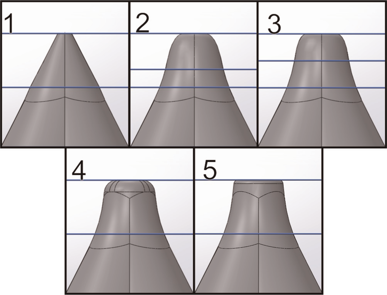
Determine the regions of the part with wall angles above φmax. These regions are referred to as the reforming region. This region is shown highlighted in yellow in Step 1 of Figure 2.
Remove a section of width l on either side of the reforming region (yellow), preserving the two-dimensional profiles of the part at either end plane (see Step 2 in Figure 2). The value of l will be varied in the next step.
Create a section with linear walls connecting the two end profiles (visible in Steps 2 and 3 in Figure 2), commonly referred to as lofting. The distance l between the planes A and B in Step 2 may be varied until the lofted region lies below φmax. This shape can now be formed in a single pass.
Create a third plane (C) at the midpoint between planes A and B. The intersection between this plane and the lofted region is a curve. By creating a curve with normal distance b from the intersection curve, a new shape can be created with similar ends to shape 3 but larger midpoint, as shown in Step 5. The hoop-direction strain in this forming step is controlled by the change in perimeter of this curve.
Repeat Steps 2–5 as necessary to generate additional forming steps until the desired part can be formed.
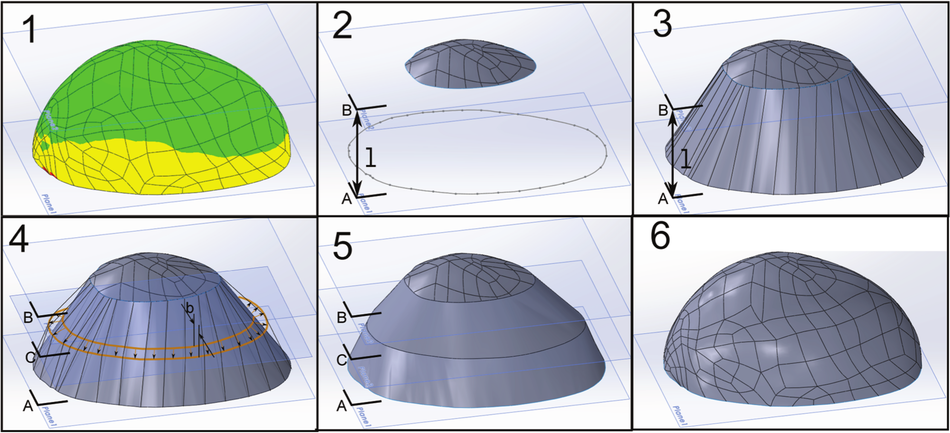
Method used to create intermediate shapes: 1: determine regions above φmax; 2 and 3: remove region above φmax and replace with straight-walled region below φmax; 4: replace lofted section from Step 3 with gradually increasing wall angle shapes.
Changes in part concavity
The second design rule presented in this section is that designers should avoid transitioning between convex and concave designs. This rule reflects the fact that SPIF tools can only ‘push’, and therefore cannot form convex shapes. To form double curvature parts, multiple setups can be used, relying on the stiffness of the previously formed section to support the region now being formed. This method has been used successfully to form a half-toroidal shape. 23
Applications of SPIF for prototyping
To demonstrate the utility of these design rules and processes, an invitation was extended to design and research groups to have prototype designs produced. The following section documents the parts made.
Engine air intake plenum
An automotive design group wanted to study the effects of air intake plenum volume on engine response. The air intake plenum is a large volume that sits in the intake system, allowing high flow rates into each intake port while maintaining a constant flow rate through the throttle valve. A total of four plenums were commissioned: lobed designs with volumes of 1.5, 2.0 and 2.5 L (Figure 3(a)), and a fourth, linear design (Figure 3(b)).
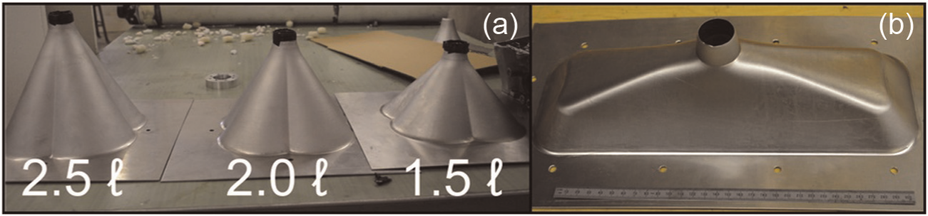
Plenums of varying size made with SPIF. Designs allowed the testing of plenum volume (a), and intake runner length (b).
Toolpath generation
Using the design rules described above, a prototype was designed, to be made from AA 3003. In order to mount to the throttle body, the plenums were required to have an open end with a wall angled at 84° from the sheet plane, while the rest of the plenum was able to remain under φmax. This region (highlighted in yellow in Figure 4) was formed using a multi-pass forming strategy.
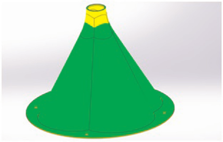
Draft analysis of the requested plenum shape. Yellow sections indicate regions above φmax.
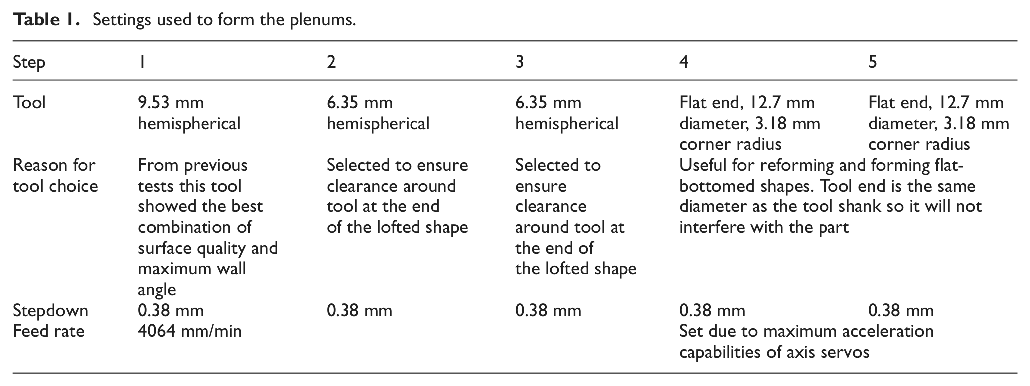
Using the method described above, intermediate models were generated for the top region and are shown in Figure 5. Table 1 shows the tools and settings used to successfully form the part.
Progressive forming stages to make the end profile of the plenum.
Settings used to form the plenums.
Powertrain guards
The following are guards made to protect the transmission components of an off-road vehicle. In this section, two iterations of the design are presented, both of which were put into service on the vehicle immediately. For the first guard design, pictured on the left in Figure 6, two forming steps were used to form the inner, then outer formed sections. The parts were formed using a 6.35-mm hemispherical tool, selected to obtain a tight corner radius near the bottom of the formed section. Finishing operations such as the mounting holes and cutting from stock were performed using conventional machining tools in the same setup.
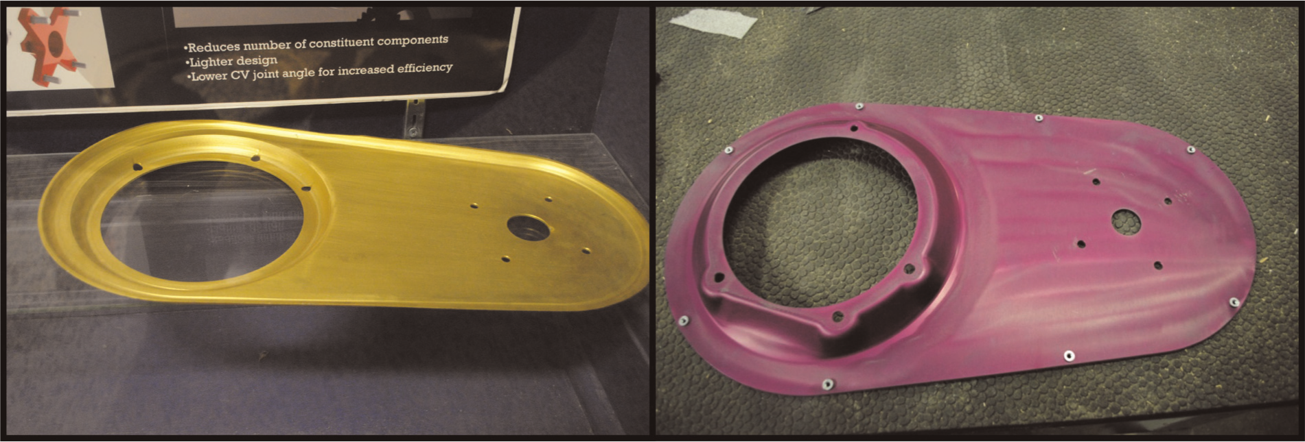
Powertrain guards made for off-road vehicles. Two design iterations are shown.
The second design (right image in Figure 6) took greater advantage of the abilities of SPIF by incorporating features such as lofted areas producing clearance for tools around mounting bolts and creating asymmetrical lofted sections to clear around structural members.
Centre bodies for an annular diffuser
Cerantola and Birk24,25 performed a series of computational flow simulations on exhaust diffuser designs for gas turbines. In order to verify the simulation results, three centre bodies were produced with SPIF, shown in Figure 7, and physically tested in a wind tunnel. SPIF was selected as an ideal process for making centre bodies because the hollow shapes that are produced can readily have pressure taps fitted. It is also worth noting that the common mounting constraints between the centre bodies allowed a single backing plate to be used for all parts.
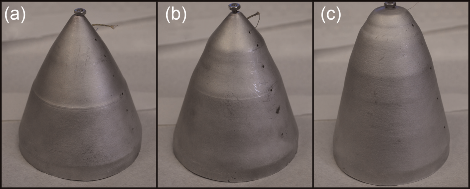
Centre body designs for an annular diffuser produced with SPIF. Holes for pressure taps are visible on the right side of each part. Parts (a), (b) and (c) are three designs for centre bodies for an annular diffuser. Holes for pressure taps are visible on the right of each part.
Toolpath generation
Intermediate steps were generated using the cut-and-loft method for each of the parts. Parts were formed using a 9.56-mm hemispherical tool for initial forming, and a flat ended tool with a radius of 3.18 mm for the additional passes. The flat ended tool allows for vertical walls to be formed with relatively tight connecting radii to adjacent surfaces. Upon completion of the formed shape, parts were removed from the stock using a conventional machining cutter in the same setup.
Patient-fitted components
SPIF is uniquely suited to the medical manufacturing field due to the flexibility and short lead times, allowing patient-specific parts to be formed directly from geometry measured from the patient. As a demonstration of the suitability of SPIF to produce patient-specific fitted components, a series of head shapes were produced based on scans of individual heads. The process to produce these parts is outlined in Figure 8. Head geometry is first generated using a three-dimensional (3D) scanner, and reconstruction software is used to generate a model from the point cloud. Intermediate models were then produced using the methods described above and formed within 1 day of scanning.
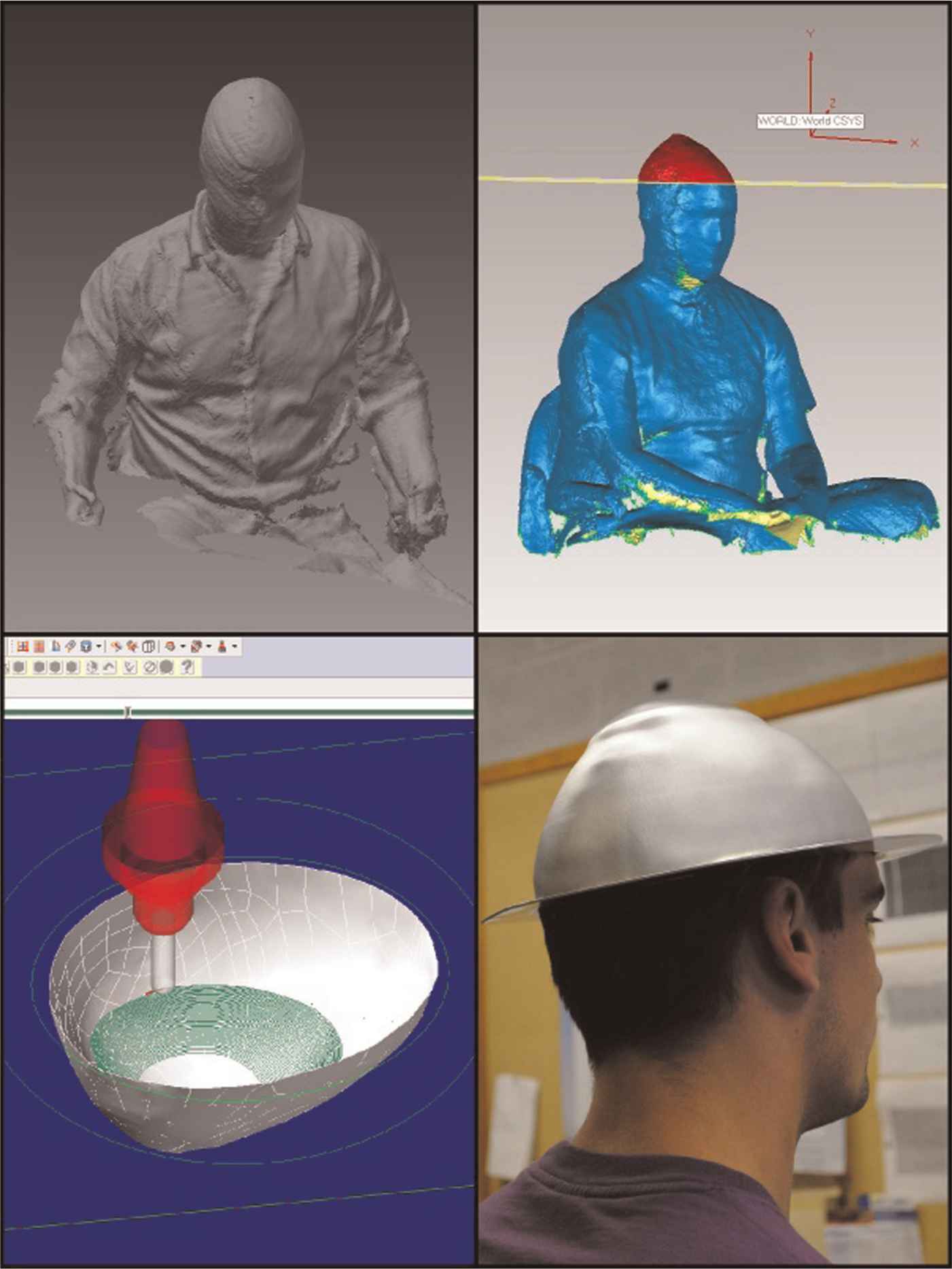
Making custom patient-fitted components (clockwise from top left): initial scan, preprocessing model, toolpath generation and final shape.
Conclusion
The ability to make bespoke shapes, with short lead times for manufacturing, has been demonstrated. The design rules presented, while a simplification of the true forming conditions, have been shown to be suitably useful in designing components provided that conservative values are used. Operational, rapid prototypes can therefore be made using any commercially available three-axis mill fitted with a blankholder. The use of a commercial CNC mill also allows for precision machined features to be added in situ, enabling high-precision features to be easily added to complex shapes.
Footnotes
Declaration of conflicting interests
The authors declare that there is no conflict of interest.
Funding
The authors would like to thank the National Sciences and Engineering Research Council of Canada and AUTO21 for their financial support to this work.