
Abstract
Incremental sheet forming process has developed the interest of researchers in the field of sheet metal forming due to high formability and capability to produce prototypes of new products at low cost and minimum lead time. Research work is going on in various front to enhance the process capabilities so that it can be explored for commercial production. In this article, progress and recent development in the field of incremental forming has been reviewed and presented for the benefit of practicing engineers and industry. The effect of various process parameters on the performance of the process have been summarized in this paper. Moreover, the issues which need attention are discussed towards the conclusion of this paper.
Keywords
Introduction
Conventional sheet metal forming methods like stamping, stretch forming etc. requires dedicated toolings specific to the sheet metal component being formed and hence are suitable only for mass production. For a single piece or small batch production, these processes are costly to deploy. Incremental Sheet Forming (ISF) process overcomes this limitation and can be used for single or batch production. The credit for developing the process goes to Leszak who was awarded a patent on “Apparatus and process for incremental dieless forming” in 1967. 1 The ISF process uses a simple hemispherical ended tool to locally deform the sheet metal as shown in Figure 1. Sheet metal blank is firmly clamped in-between the backing plate and the blank holding plate. Sheet metal blank is formed into any complex shape by moving the tool in a defined tool path controlled by NC Part Program using CNC machines. The process is suffering from the limitations like long processing time, poor geometrical accuracy, not suitable for mass production, and difficult to produce the true cylindrical shape.
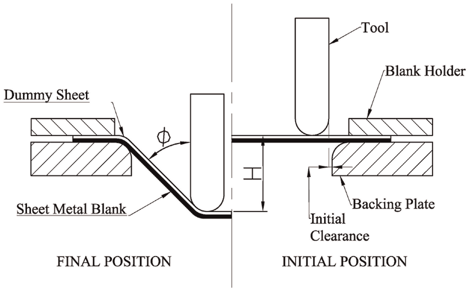
Schematic representation of the ISF process.
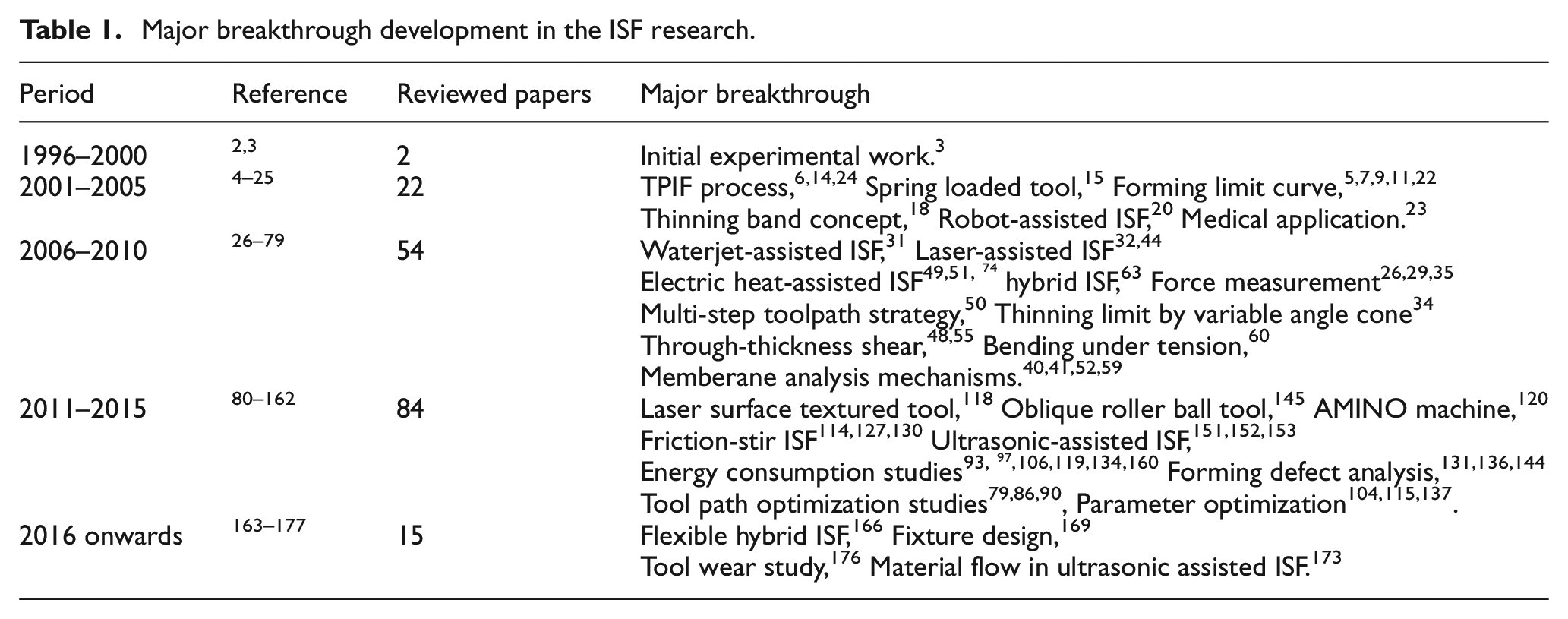
Major breakthrough developments occured in the ISF research area have been tabulated in Table 1 which has expanded the knowledge base of the process. ISF process have been reviewed by Hagan and Jeswiet, 10 Jesweit et al., 19 Emmens et al., 71 and Echriff & Hrairi. 83 In the recent past a comprehensive review on deformation mechanics, modelling techniques and forming force analysis is given by Li et al. 168 Duflou et al. 171 have also presented state-of-the-art review on ISF process with special emphasis on hardware requirements, process window enhancement, tool path strategy and numerical simulation of the process. The aim of this review paper is to present the developments in the ISF process in a classified manner as shown in Figure 2. The effect of different process parameters on performance of the ISF process is compiled for a better understanding of the process and further improvement.
Major breakthrough development in the ISF research.
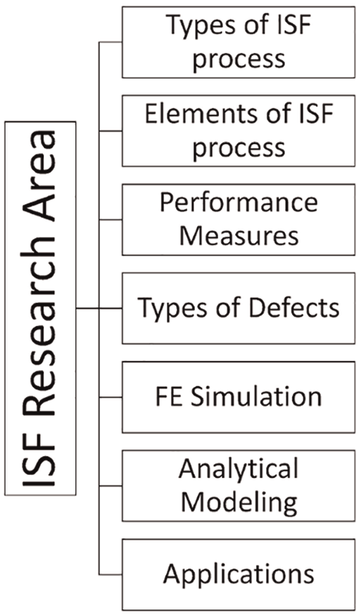
ISF research areas.
Types of the ISF process
Over a period of 20 years, different ISF processes and variants (Figure 3) have been developed. Based on the direction of forming, the ISF process can be classified as negative forming and positive forming ISF process (Figure 4). In negative forming, sheet metal component is formed from a larger base to the smaller base (Figure 4(a)). Whereas in positive forming (Figure 4(b)), sheet metal component is formed from a smaller base to the larger base by moving the fixture along the guidepost.
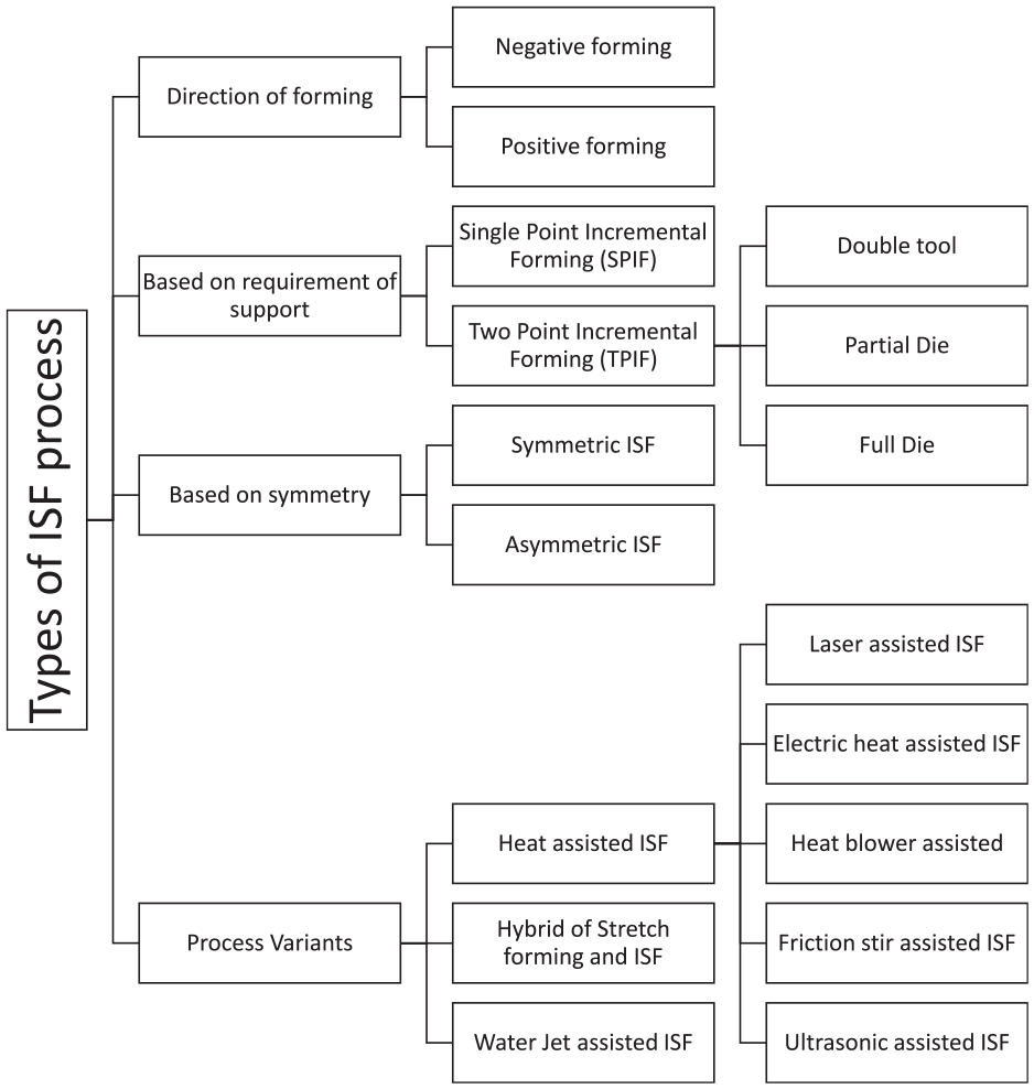
Types of ISF processes.
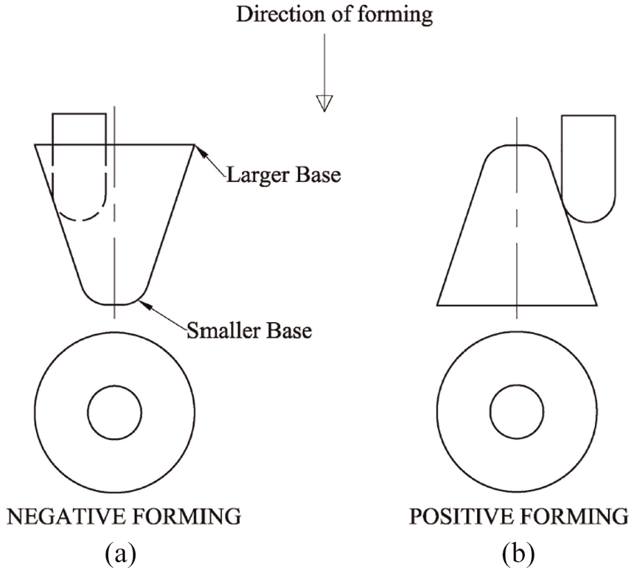
Negative and Positive ISF processes.
If a single tool with no die support is used in the case of negative forming, the process is known as dieless forming or Single Point Incremental forming (SPIF) (Figure 1). If a single tool with female full die as shown in Figure 5(a) is used in negative forming the process is referred as two-point incremental forming (TPIF). 30 Negative forming can also be achieved by providing coordinated motion to two tools (forming tool and counter tool to support the sheet metal blank) each operated by separate robots or custom made machine100,158 (Figure 5(b)). When two tools are operated using different robots the process is called roboforming which facilitates in preparing undercuts. 65 In the positive forming male support in the form of partial die6,39 (Figure 5(c)) or full die (Figure 5(d)) is used. In two point incremental forming the formability is better as the mode of deformation is only plane strain. Whereas in SPIF process along with plane strain bi-axial mode of deformation is also present. 11
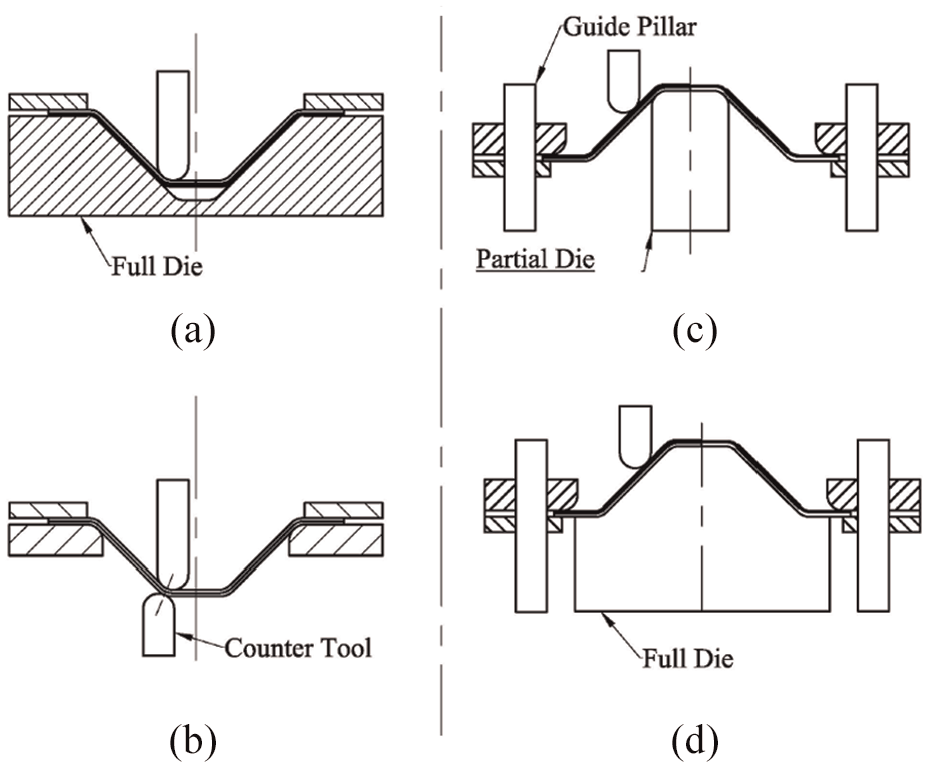
TPIF process (a) Negative forming with full die (b) Negative forming with double tool (c) Positive forming with partial die (d) Positive forming with full die
ISF process can also be classified as symmetric incremental sheet forming (SISF) and asymmetric incremental sheet forming (AISF) process. Symmetric components are mainly produced by spinning process, however, they can also be formed by ISF process. Asymmetric components are mainly produced by AISF process which is generally referred to as ISF process.
Moreover, in a heat-assisted ISF processes additional energy source (laser beam, electric heat, heat blower, friction-stir, and ultrasonic vibration) is used to generate localized heat which softens the material and in turn improves formability of difficult to form materials (Figure 3).
In a laser-assisted ISF process, a laser beam continuously impinge on sheet metal blank ahead of tool either from opposite side of a tool32,44 or from the same side of tool 81 to achieve dynamic local heating. Nd-YAG laser32,44 and fiber-coupled diode laser 124 were used as the lasing source. This process is having the advantage that the heating zone can be controlled both in location and size, however, the cost of the equipment is high.
In an electric heat-assisted ISF process, DC current is used to soften the metal in localized area by resistance heating phenomenon.51,74 Homogeneous heating of the sheet metal blank can also be achieved using DC power source connected to copper electrodes, 117 band heaters, 98 heat blower 45 or heating chamber. 49 Electric heat-assisted process is having the benefit of low equipment cost, however, the process is having associated problems like lubrication at elevated temperature, poor surface quality of formed component and high tool wear. Friction stir-assisted ISF process has also been proposed by researchers. 130 This process is also suffering problems similar to heat-assisted process like high tool wear and poor surface quality. In this process the heat input to the sheet metal blank can not be controlled as in the case of electric heat-assisted process.
Ultrasonic vibration assisted ISF (UISF) process151–153,167 have been developed which reduces the forming force, spring-back and surface roughness. However, this process requires additional ultrasonic equipment alongwith the CNC milling machine. In a recent study on UISF process performed by Li et al. 173 shows improvement in formability due to increase in material flow area which results into participation of more material in plastic deformation.
To reduce the forming time, a Hybrid ISF process is also proposed by Aragi et al. 63 in which stretch forming (creates pre-form) is followed by ISF process (creates pockets). Lu et al. 115 produced car fender component successfully by using this process.
Water jet ISF process is another variant developed by Jurisevic et al. 31 in which a solid hemispherical ended tool is replaced by high-pressure waterjet. Water jet ISF has the advantage that it improves the surface finish as there is no physical tool contact with sheet metal blank, however, it adversely affects the accuracy, forming time and energy consumption.
Elements of ISF process
The parameters influencing the performance of the ISF process have been studied and classified as main elements of the ISF process as shown in Figure 6. They have been discussed in detail in the following sections.
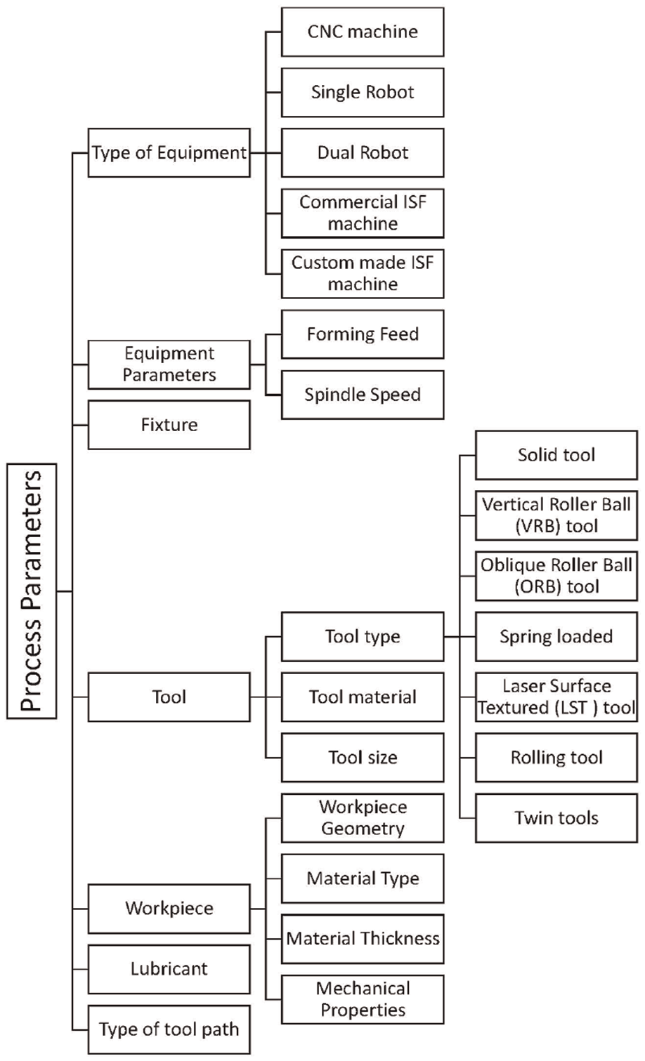
Elements of the ISF process.
Type of equipment
Equipment in the ISF process provide power to move the tool along the required tool path. Researchers have used Vertical Machining Center,91,109 Horizontal Machining Center,50,82,99,134,150 Single robot,20,32,44,82,116,134,140,142 Dual robots,65,87,101 custom made ISF machine100,143 and commercial ISF machine63,75,132,134,135,139,160 to carry out experiments. Machining centers are general purpose machines and can be used for variety of shapes. Though, robots provides flexibility in operation, they are not suitable where high forces are involved, high accuracy is desired and shapes with undercuts are to be formed. Commercial machines can provide high forces and can produce components with better geometric accuracy. First prototype machine dedicated to the ISF process was developed by AMINO corporation in 1996. 120
Process parameters
Four main process parameters which is reported to have effect on formability are forming feed, spindle speed, step-depth, and tool path.
Forming feed
Study of the ISF process with feed rate ranging from 26.67 90 to 8890 78 mm/min has been reported in the literature. Feed rate in the ISF process affects the time of forming and in-turn energy consumption. Chezhian Babu & Senthil Kumar 92 reported an improvement in formability at lower feed rates but with a corresponding increase in the forming time. However, Fan et al. 51 reported adverse effect of too low (sheet metal burns) or tool high feed rate on formability of sheet metal in electric heat-assisted ISF process. Higher feed rates can be employed in friction stir-assisted ISF process as compared to electric heat-assisted ISF process. 130 These contradiction suggests that forming feed is having interaction effect with other process parameters and requires to be optimized for the process under consideration. Feed rate of 100 mm/min 31 and 2000 mm/min 167 was found successful in water jet-assisted and ultrasonic-assisted incremental forming respectively.
Spindle speed
ISF process can be carried out without giving rotation to the tool or with the rotation of the tool (016,77,94,95,106,144,156,160,162 to 10000 127 rpm). To have a minimum friction pure rolling condition should be set by choosing appropriate spindle speed and feed for a given tool diameter.12,16,22,137 It is observed that as the rotational speed increases the formability increases.41,114,159
Step-depth
Similar to rapid prototyping, in which material is added layer by layer, in ISF process also components are formed layer by layer. Distance between two successive layers is step-depth which impacts the formability and surface finish. Step-depth can be kept constant or can be variable. Researchers have studied the ISF process with step-depth in the range of 0.1 9 to 1 14 mm. Increase in formability is found with an increase in step-depth while working with PLA and PVC plastic materials. 159 However, formability of metals found to be decreased with the increase in step-depth20,175 or marginal effect 147 of step-depth on formability.
Tool path
Tool path is the trajectory along which the tool traverses to give the desired shape to the sheet metal blank. The geometry of the formed component strongly depends on the type of the tool path (Figure 7) selected. 109 Tool path can be classified as Constant step-depth, Variable step-depth, and Helical tool path (Figure 8(b)). Constant step-depth tool path (Figure 8(a)) has been widely used by the researchers.35,91,92 Variable step-depth tool path results in better formability when the slope of the component gradully decreases towards the bottom 42 (Figure 8(c)). In such components, tool path is generated 30 using constant scallop height concept to have more contours at bottom. However, scallop height is the concept of machining and more appropriate term to use is step-in (SI) for SPIF or step-out for TPIF as shown by the line 1 to 2 in Figure 8(a). By maintaining a constant step-in value, the generated tool path gives more contours at the bottom as shown in Figure 8(d) which improves the geometric accuracy.
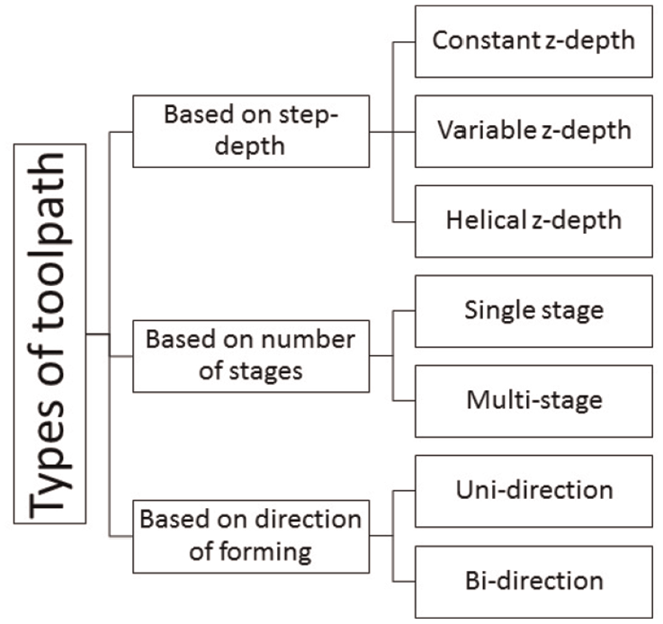
Types of tool path.
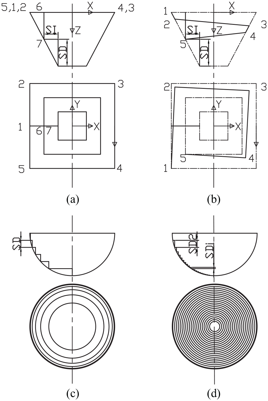
Tool path (a) Constant step-depth (b) Helical (c) Variable step-depth (d) constant step-in.
While taking the step-in motion tool leaves the contact and allows the component to spring back. However, in an experimental study Matsubara 6 used a movement of the tool along an inclined line (1–7) which helps continuous contact between the tool and sheet. Tool path should be designed in such a way that the forming starts from the lower stiff area (Dai et al. 3 ). Forming near the stiff areas (i.e. near clamped periphery) leads to splitting along the boundary.
Tool path can also be classified as a single-stage and multi-stage tool path. Multi-stage tool path reduces excessive thinning (Young and Jesweit 18 ) and hence improves the formability. Multi-stage tool path facilitates the tool entry at lower angle which shifts the deformation mode from near plane strain to bi-axial strain.
Tool path can also be classified as an uni-directional 75 or bi-directional tool path. The part twists about its axis under the influence of the uni-directional forming forces involved when the uni-directional tool path 6 is used. Bi-directional tool path prevents twisting of the component in which direction of the tool movement reverses after each loop.
Alongwith the use of CAM software, different algorithms (genetic algorithm 2 , eqi-potential line principle 115 , graph topological method 137 , modified adaptive slicing algorithm79, finite element analysis with sequential quadratic programming (SQP), 90 tool shift 158 ) have been proposed to generate the tool path for the ISF process to improve formability.
Fixture
The fixture (Figure 1) is used to clamp the sheet metal rigidly during forming. The backing plate is having a cut out to replicate the contour of the component at its base. 24 Moreover, radius is given at the cutout edges to prevent tearing of the sheet at the contact zone while forming. Die may or may not be present depending on the type of the ISF process (refer Section 2). In positive forming, die corresponding to the shape of the component is used. Die material can be a low-cost epoxy resin6,30 Aluminium, 63 urethane rubber 6 or mild steel.6,55 Recently Siddiqi et al. 169 shown the methodology to design and validate the fixture for the positive TPIF process in which 3 pillar design was found suitable from the point of view of kinematic accuracy and lateral stiffness.
Tool
A tool through which forming force is applied always remain in contact with the sheet metal blank. Researchers have studied the effect of tool shape, tool size, and tool material on formability and have been summarized in this section.
Tool shape
The solid hemispherical ended tool is the most widely used tool in the ISF process. Formability enhancement has been reported using Vertical roller ball (VRB)4,5,9,132 tool as rolling friction prevails at tool and sheet metal interface. In the VRB tool, an arm holding the ball interferes with the sheet metal component and thus limits the maximum angle to which component can be formed. Oblique roller ball (ORB) 145 overcomes this limitation. The spring-loaded tool has also been proposed by Ceretti et al. 15 to maintain the constant forming force and thus preventing the chances of fracture. To improve the tribological conditions, use of laser surface textured tool is also reported by Xu et al. 118 Rolling tool (to reduce the friction) and two or more tools operating in synchronization (to increase the forming speed) have been proposed by Bambach et al. 122 for the incremental hole flanging process. Among the four different tools conceptualized, Kwiatkowski et al. 68 reported “Twin Tool” to be the most feasible tool for increasing the speed of the forming.
Tool material
Though the forming forces involved in the ISF process are low, the tool materials should be selected according to wear characteristic of sheet metal blank and tool. Different tool materials have been used for the forming tool like high carbon steel,8,12,39 EN36, 161 cold die steel, 6 air hardened D2 tool steel,118,123 HSS34,46 47 53 61 67 ,88,91,127,138,162,32,44,51,70,74,132,160, Silicon carbide, 92 cemented carbide62,98 etc. In the case of ultrasonic vibration assisted ISF process SS316 was found to be suitable due to its favorable acoustic characteristics 153 .
Tool size
Selection of the tool diameter (2 53 to 3081,90,132,135 mm) with reference to the thickness of the sheet is an important criterion for the successful forming of the component. 131 Chances of success of forming in the ISF process increases if the radius of the tool is more than three times the thickness of sheet metal blank but smaller than five times the thickness of sheet metal blank. 6 Tool radius in the order of 0.1 mm and 0.5 mm have also been reported 62 in microforming of Aluminium foil of 50 µm thickness. It is observed that increasing the tool size increases contact zone which in-turn reduces the level of strain in the sheet metal blank. 9 Li et al. 132 have also concluded that tool diameter (10–30 mm) should be as large as possible to delay the fracture in forming of large components. Ham and Jesweit 33 have discussed effect of the tool diameter (4.76–9.52 mm) on the successful forming of a component with various aluminium alloys. Tool size effect is found to be material dependent 33 . Moreover, tool diameter may have interaction effect with two other parameters namely thickness and step-depth. However, in electric heat-assisted forming 51 using too low tool size causes sheet burning and too high tool size causes heat to dissipate over a larger area of contact leading to lower formability.
Workpiece parameters
Effect of workpiece geometry, material type, material thickness, mechanical properties, and sheet metal blank temperature has been reported in various research papers.
Geometry of component to be formed
Wide range of geometrical shapes like cone, pyramid, automotive component, medical component and miscellaneous shapes could be readily formed using the ISF process (Table A1 to Table A7 in Appendix). Cone and pyramid 93 frustum have been most widely studied because of its geometric simplicity and ease in analyzing forming force, power consumption, strain distribution etc. Moreover, in formation of the cone plane strain condition prevails and in pyramid forming biaxial strain condition prevails which helps in establishing fracture forming line (FFL) for prediction of failure in other components with same material. Car bodywork,42,30 Car hood assembly, 120 LOGO mark on door panel, 120 Feature line on door panel, 120 Car fender, 115 Engine air intake plenum 155 Car door shell, 98 Powertrain guard 155 are some of the exampels from automotive industry. Component of small size like miniature car as reported by Obikawa et al. 62 (1.0 mm × 0.4 mm × 0.23 mm) to the large size of the order of 1400 mm × 700 mm × 500 mm, as reported by Matsubara, 6 is possible to produce by the ISF process.
Material type
Various materials like Aluminium alloy (Table A1 and Table A2 in Appendix), Steel (Table A3 in Appendix), Copper (Table A4 in Appendix), Titanium (Table A5 in Appendix), Magnesium (Table A6 in Appendix), and Polymer (Table A7 in Appendix) have been studied by the researchers. Aluminium can be formed easily at room temperature, however, Titanium and Magnesium grades are difficult to work at room temperature and needs heat-assisted ISF processes.
Polymer: ISF process has also been applied to form polymer materials64,103 like Polyoxymethylene (POM), Polyethylene (PE), Polyamide (PA), Polyvinylchloride (PVC), Polycarbonate (PC), and Polylactic Acid (PLA).
Sandwich panel: ISF process has also been applied to different sandwich panels (MS/PP/MS, Al/PP/Al, SS/SS fiber/SS and Al/Al foam/Al). 48
Blank thickness
The thickness of the blank used ranges from 0.21 mm (Thibaud et al. 102 ) to 13.5 mm (Jackson et al. 48 ). Dummy sheet is also used to protect the sheet metal blank 52 or weld seam 54 from damage due to direct contact with the forming tool, however, it decreases the formability. Use of Tailor Rolled Blank (TRB) 14 and Tailor Welded Blank (TWB) 54 is also reported in the ISF literature.
Mechanical properties
Effect of strain hardening exponent, 13 strength coefficient, anisotropy, 61 ultimate tensile strength, the percentage elongation 13 and grain size 109 have been carried out by the researcher. Materials with higher strain hardening exponent and high % elongation exhibits higher formability. As thickness to grain diameter ratio decreases it deteriorates formability which can be explained by Hall-patch effect.
Sheet metal blank temperature
In a heat-assisted ISF process, the temperature is an important factor to be controlled and studied. Van Sy and Thanh Nam
117
controlled the temperature of the sheet metal blank to two levels (200°C and 300°C) and observed improvement on formability (Maximum wall angle of 85°C), geometric accuracy (of the order of 0.1 mm), springback and surface finish. Ambrogio et al.
49
observed 250°C (
Lubricants
A lubricant is applied in the contact zone between the forming tool and sheet metal blank to reduce friction and forming force which in-turn improves formability and surface finish. Deep drawing oil 6 , cutting oil,59,78,123 bearing oil, 11 gear oil, 97 used cooking oil ester, 97 SAE40 oil, 161 Lithium grease,24,117 extreme pressure grease,48,55 PTFE based grease,94,123 mineral oil,47,58,80,134,145,154 solid graphite powder,74,117 boron nitride spray, 74 aqueous suspension of graphite,58,154 paste of grease and MOS2, 117,141 dry MOS2,49,51,61,74,88,158 vegetable ester based cutting fluid, water-insoluble cutting fluid 124 and pure water 62 have been used by the researchers.
Use of copper-based anti-seize compound (electric heat-assisted 130 ), carbon-based dry-film lubricant (laser-assisted forming 81 ), Nano-K2Ti4O9 whisker mixed with solid graphite (warm forming 67 ), and Nickle disulfide metal matrix composite (electric heat-assisted 74 ) have been reported in the hybrid ISF process.
Performance measures in the ISF process
Ten performance measures are used by the researchers to evaluate the ISF process as compiled in Figure 9.
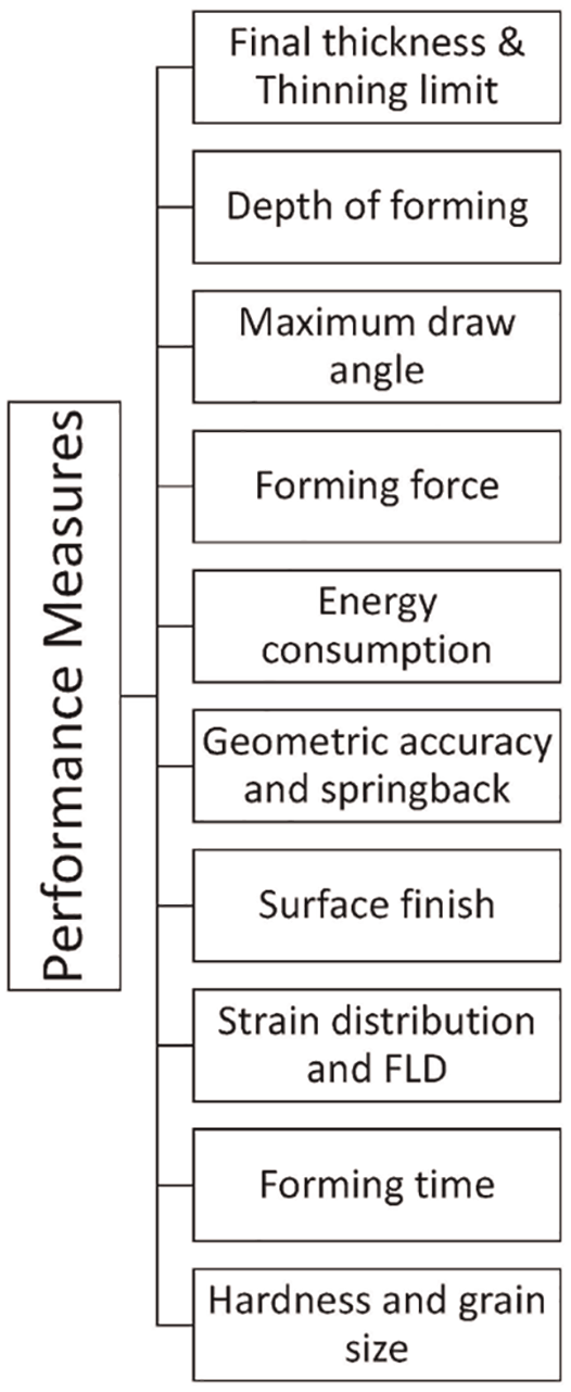
ISF performance measures.
Final thickness and thinning limit
In the ISF process, thickness in the flange area and at the bottom base is found to be almost the same as that of the parent sheet metal blank indicating that this region does not experience any deformation. However, in the wall region, the maximum reduction in thickness is observed which forms a thinning band. Thickness reduction of 80% (commercially pure Aluminium 6 ), 66% (FPG copper sheet 102 ), and 75% (EDD quality steel 161 ) have been observed while working with different materials. Table 2 gives the % thinning observed in some of the research work. Hamilton and jeswiet 78 attributed thinning as a geometry effect i.e. it depends on forming angle. The thinning band can be attributed to the stretching and through-thickness shear effect in a direction perpendicular to the tool motion which was prooved experimentally by Alwood et al. 55 by performing a test on copper plate. Thickness distribution in the ISF process normally follows the Sine law. Bambach et al. 75 have proposed better model than sine law for thickness prediction of 2D and axisymmetric components based on the assumption that the final shape of the component evolved by passing through a number of intermediate shapes. During the deformation, material deforms normal to the surface of current shape. However, the model excludes the effect of bending, frction between tool & sheet and material behaviour.
Summary of performance measures in the ISF process.
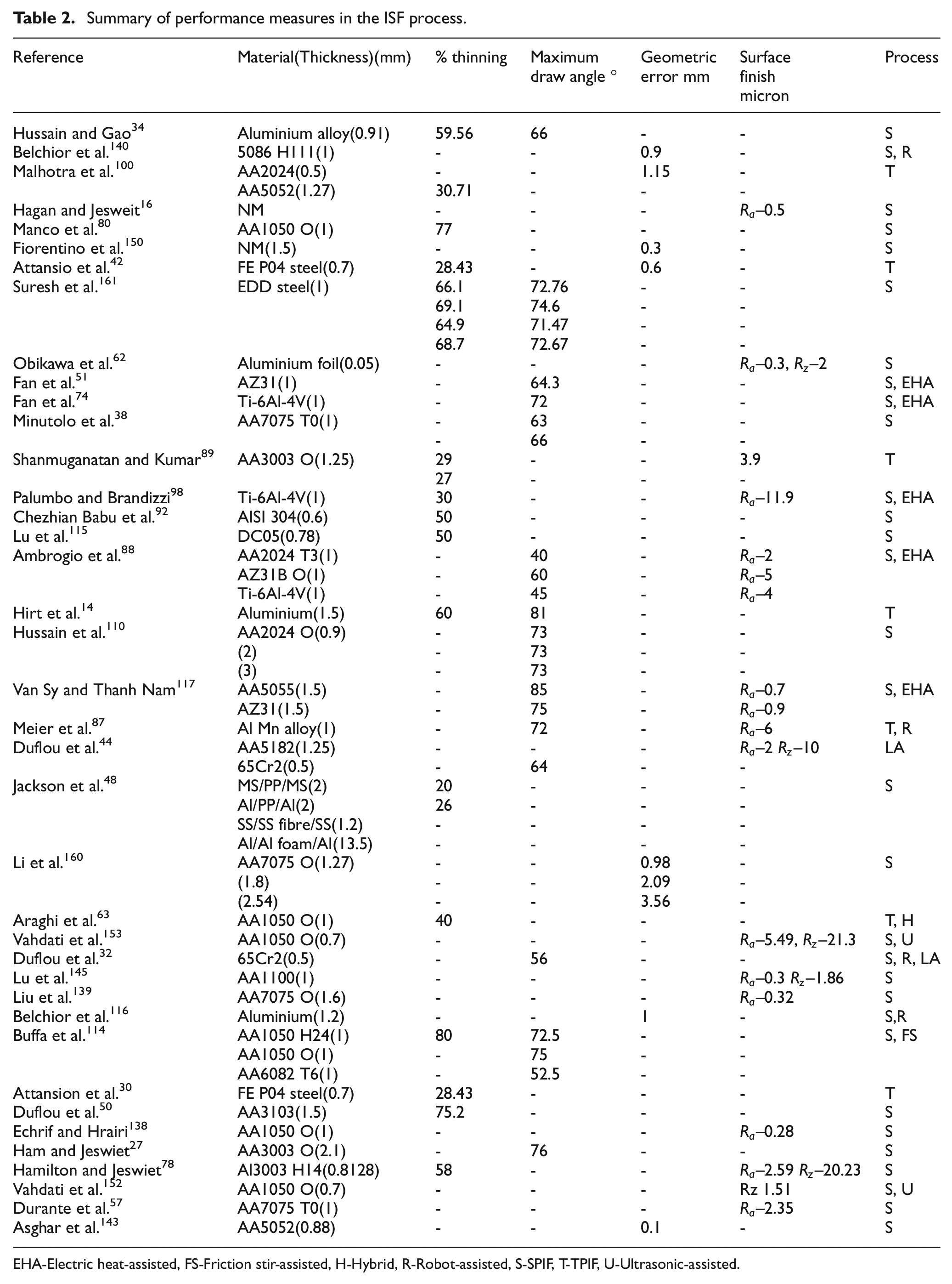
EHA-Electric heat-assisted, FS-Friction stir-assisted, H-Hybrid, R-Robot-assisted, S-SPIF, T-TPIF, U-Ultrasonic-assisted
Selection of the tool path and the ISF process affects the thickness distribution significantly. Different forming tool path leads to different strain distribution and hence thickness variation.3,80 Young and Jesweit 18 formed automotive heat shield with reduced thinning using double pass SPIF process. However, double pass strategy increases the forming time, hence, compromise is to be made between improved formability and increased forming time. In a multi-stage forming, it is observed that material was shifted from the bottom base to form the wall of the component and thus improving the forming angle to 70°. 50 Constant wall thickness can be achieved in accumulative-DSIF strategy as compared to SPIF strategy. 100 Wall thickness was found to be higher in TPIF process as compared to the SPIF process for the same geometry of component. 39 Uniform distribution of thickness with a reduction in excessive thinning in the ISF process can be achieved by using a hybrid process of ISF and stretch forming. 63 Zhang et al. 166 have used a hybrid process of multipoint forming and the ISF process to improve the thickness of hemispherical component by 46%. Optimum selection of the parameters leads to the optimization of the performance measures. Asghari et al. 165 have shown the application of grey relational analysis (GRA) to optimize the minimum thickness, springback and surface roughness simultanuously giving equal weightage to each response variables. Higher value of tool diamater (15 mm), lower value of cone angle (63°), higher speed (800 rpm) and lower step-depth (0.2 mm) leads to the maximum value of Grey Relational Grade (GRG) and optimization of the objective function.
Depth of forming
Forming depth (depth at which fracture occurs) achieved in the ISF process depends on input parameters like tool type and size, tool path, speed of forming, and process types. The ORB tool 145 has a positive effect and laser surface textured tool 118 has a negative effect on the forming depth. Helical tool path as compared to constant Z-depth tool path forms the component to the full depth. 102
Ebrahimzadeh et al. 170 have reported a higher formability (Forming height of cone) in TPIF process as compared to SPIF process while working on AA5083 friction stir welded blank. Forming depth can also be improved using TPIF process with two tools along with the superimposed pressure, 87 laser-assisted ISF process, 81 and Ultrasonic vibration-assisted ISF process. 153
Maximum draw angle
Draw angle (
A material having a particular thickness can be formed to a critical draw angle in a single-stage. 155 Beyond this critical value, the multi-stage tool path strategy has to be used. The square pyramid was successfully formed with a wall angle of 81° using multi-stage strategy. 14
Moreover, warm forming enhances the forming limit. Duflou et al. 32 (32°–56°) and Duflou et al. 44 (57°–64°) have reported improvement in draw angle using laser-assisted ISF process. Electric heat-assisted ISF process improved the maximum wall angle for AA2024-T3 (30° to 40°), AZ31B-O (less than 20°–60°) and Ti6Al4V (20°–45°) materials as compared to cold forming carried at room temperature. 88 Maximum draw angle of 85° was obtained using electric heat-assisted ISF process while working on AA5055 aluminium sheet. 117 AZ31 material can be formed to the higher depth and wall angle in warm ISF process (60°, 300°C) as compared to forming at room temperature (30°,3 mm depth). 49 While forming Ti6Al4V titanium sheet maximum forming angle of 72° was observed while working at 500°C in electric heat-assisted ISF process. 74 Formability curve (limiting forming angle vs. rpm) have been proposed 114 and it is observed that for AA1050-H24 aluminium alloy maximum forming angle of 72.5° could be formed at 8000rpm tool rotation.
Forming force
Knowledge of forming force helps to understand the deformation mechanics and design of fixture & machine components. Forming force monitoring also helps in failure prediction and prevention. 57 Due to localized deformation characteristic of the ISF process, forming force in ISF is very low (25 kN) as compared to the conventional press machine (8000 to 10000 kN). 120 Bouffioux et al. 69 have used two tests (indent test and classical test) to obtain the material data identification and incorporated in FE analysis. With this, the force prediction was improved as both in-plane and out of plane strains were accurately predicted as compared to material data taken only from simple classical test.
Based on whether thinning is predominant or material strain hardening is predominant, three main force trends have been observed by Filice et al.:
26
1. Steady-state force curve (low draw angle) 2. Polynomial force curve (small step-depth, large tool diameter, and large draw angle) and 3. Monotonically decreasing force curve (very large draw angle). Initially, force is found to increase due to bending mechanism as the contact between the tool and sheet metal gradually develops.
35
Once the force curve peaks and the contact is fully developed, steady state or force curve with decreasing slope have been reported which is attributed to work hardening and softening mechanism. In micro-SPIF process
109
also monotonically decreasing force curve (
Force trend in the ISF process depends on sheet thickness, wall inclination angle, tool diameter, and step-depth.26,29 As the radius of the tool increases forming force increases,26,96,105,147 as it increases the contact area. The similar trend was also observed while working with the sandwich panel (MS/PP/MS) 48 . Increasing the step-depth have similar effect48,96,105,159 as it leads to larger local deformation. As the wall angle increases, larger thinning is imposed on the sheet which in-turn increases the forming force. 156
Tool rotation leads to lower forming force 57 as sliding friction condition changes to rolling friction condition. Moreover, at higher speeds high local heat is generated under prevailing friction condition which softens the metal and reduces the forming force. Similar phenomena have been reported for metallic (AISI 304) 105 as well as polymeric materials 159 . Eyckens et al. 70 predicted the forming force and through thickness shear using FE simulation in which rotation and friction co-efficient (0.09) were considered.
Laser-assisted ISF process reports a 50% reduction in forming force by using a dynamic local heating system using laser. 44 A similar trend is found for AZ31 magnesium alloy 49 at the temperature of 200°C to 300°C. The reason behind the reduction in force can be attributed to softening of material at elevated temperature which requires lower forming force to deform. Vahdati et al. 153 and Amini et al. 167 reported a reduction in forming force in ultrasonic assisted ISF process which is attributed to acoustic softening and reduction in friction. Li et al. 173 in their study on UISF process attributed the reduction in forming force to reduced flow stress (due to increase in material flow area) and reduced contact time (due to seperation effect of ultrasonic vibration).
In micro-SPIF process 109 effect of grain size on forming force is analyzed. As the grain size increases peak Z-force decreases which is in-line with the famous Hall-Petch effect.
Measurement of the force helps in identifying the imminent failure of the sheet metal component. Ambrogio et al. 29 (gradient) and Petek et al. 66 (skewness) proposed failure prevention strategy by measuring the parameters based on force curve. Force was also correlated with the defect and it was found that pillow defect and corner fold increases the forming force. 144
Energy consumption
Total energy required in the ISF process is summation of friction energy (depends on type of machine) to overcome friction in moving machine element and deformation energy (depends on process parametes). Studies performed by Ingarao et al.
93
on energy consumption show that stamping consumes less energy than SPIF process. The reason behind this is that, stamping although being high force process, is having less displacement. Whereas, SPIF although being low force process, is having a longer displacement path. Reducing the step-depth and forming feed leads to longer forming time and more energy consumption.
134
In the same study, it was found that the total energy requirement is least in the case of a robot (181 kJ) as compared to AMINO machine (223 kJ) and CNC milling machine (1200 kJ). Li et. al
160
found increase in the sheet thickness and wall angle results in an increase in deformation energy. The optimum parameters leading to the reduction in processing energy were suggested by Liu et al.
177
According to their study processing energy could be reduced by increasing the feed rate (from 1000 mm/min to 4000 mm/min) and increasing the step-depth (from 0.2 mm to 1.5 mm). Among the parameters varied during the study carried out by Bagudanch et al.,
106
it was found that free spindle rotation consumes 50% less power than the rotation of the tool at 2000 rpm. Energy consumption and
Geometric accuracy and springback
Geometric accuracy of the component formed by the ISF process (3 mm deviation) is found to be poor as compared to conventional sheet metal stamping process (0.21 mm deviation) which is the requirement of industry. 73 As per the study performed by Allwood et al. 21 application of the ISF process in the industry is possible if the component with geometric tolerance of order 0.3 mm, smallest feature radius of 1 mm and material thickness up to3 mm can be formed. Allwood et al. 73 categorized geometric accuracy as Clamped, Unclamped, and Final-accuracy.
Geometric error measured in some of the research work have been tabulated in Table 2. Geometric inaccuracy in ISF formed component is mainly due to sheet bending close to the backing plate, 17 springback effect and pillow defect at the base. Pillow defect (flat bottom bulges up) at the base is created because tool only deforms the borders of the base and not the base entirely (Benedetti et al. 163 ). Recovey of elastic strain (from circumference to the center of the bottom) can be attributed to the pillow defect. Ambrogio et al. 36 through ANOVA analysis have found sheet thickness and part depth as the most significant factor affecting the geometric error. The pillow depth was most affected by tool diameter and part depth. Hussain et al. 85 developed empirical model to predict the bulge height in the ISF process, however, the model was established for one material only and requires validation to apply the same for other materials. Hussain et al. 136 also suggested to use large tool radius to control the size of the pillow defect as it leads to the favourable compressive stress state. Strategies to improve the geometrical accuracy in ISF process can be a use of flexible support, use of counter pressure, multipoint incremental forming, positive forming, and optimization of tool path. 37 Attansio et al. 42 improved the geometric accuracy by setting the step-depth and scallop height to a lower value. Effect of partially cut-out blanks is reported, however, with no significant beneficial effect on the accuracy of the formed component. 73 Li et al. 160 reported that thinner sheets give better geometric accuracy. Decremental slope strategy 104 is found to be better than single slope strategy in reducing the thinning and geometrical error. Using accumulative DSIF maximum deviation from the desired geometry was 1.15 mm. 100 By using pure out-to-in motion tool path strategy stepped features are produced on the final formed component due to accumulated rigid body translation caused during the intermediate stage. Combined strategy (out-to-in followed by in-to-out) helps in eliminating the stepped feature. 86 Fiorentino et al. 150 improved the geometric accuracy of formed component by using Iterative Learning Control (ILC) technique. Lower geometric deviation (0.9 mm) was observed with feature-based tool path generation as compared to constant z-depth tool path generation (1.5 mm) while forming a cone shape with double bottom. 115 Hirt et al. 14 proposed a toolpath correction method to improve the geometric accuracy in which deviation vector was calculated based on the cloud of points obtained by CMM measurement and compared with actual geometry. In a similar work geometric accuracy was improved by modifying the tool path based on deviation measurement by 3-D mechanical digitizing system by Ambrogio et al. 25 By incorporating the compensation in the tool path due to tool deflection and sheet deflection Asghar et al. 143 improved the geometric accuracy.
Geometry accuracy can also be improved by dynamic local heating using laser. 44 Geometric accuracy in clamped condition was found to be improved with laser-assisted ISF process which is an indication of a reduction of springback and unwanted plastic deformation. 32 Geometric accuracy in Roboforming can be improved by using model-based or sensor-based approach. 65
Process/Machine coupling approach is also proposed by Belchior et al. 140 for improving the accuracy (from 4 mm to 1 mm deviation) of forming in ISF process. In Roboforming it is difficult to achieve geometric accuracy on the formed component due to low stiffness of the robot system. Correcting the tool path, based on force prediction using FEM and its subsequent use in MBS simulation can help in reducing the geometric error. 101 In this method of correcting the links are assumed to be rigid and joints are assumed elastic which inturn may lead to inaccuracy. It can be improved by considering both link and joint as elastic 116 and then compensating for elastic deformations.
Springback is a common phenomenon occurring in any sheet metal forming process due to elastic strain recovery which affects the accuracy of forming. Through experimental work and numerical simulation Radu et al. 113 reported decrease in part accuracy with decrease in tool diameter and increase in step-depth. In laser-assisted ISF process negligible residual stress were found 124 with subsequent reduction in springback. Vahdati et al. 153 reported a reduction in springback coefficient from 1.07 to 1.03 when ultrasonic vibration was imparted to the tool.
Surface finish
The surface condition of the sheet metal component changes as compared to the initial surface condition in the ISF process. Table 2 gives surface roughness values obtained by various researchers in ISF produced components. The surface of a tool side of sheet metal component exhibits waviness (due to tool path) as well as roughness (due to surface strain) due to contact with the tool. 139 Surface roughness on the tool side is higher than the surface roughness on the other side 117 . Decreasing the step-depth and using variable step-depth improves surface quality. 30 Compared to zero tool rotation, rotating the tool reduces the surface roughness value. Similar results were obtained by Josue and Alvares 176 in which increasing the tool rotation speed has improved the surface finish, however, it lead to the problem of tool wear. Tool rotation speed has also a negligible influence on the surface roughness. 57 Among the different types of tools under study 145 (rigid tool, VRB tool, and ORB tool), it was found that the ORB tool gives the lowest roughness values. Increasing the tool diameter is found to improve the surface finish because larger diameter tool produces large indentation which becomes indistinguishable in subsequent forming path. 89 Liu et al. 139 used Box-Behenken design with multi-objective optimization to minimize the surface roughness and found thickness and step-depth the most influencial factor affecting the surface roughness. In a TPIF process contacting surface was found to have glossy appearance due to ironing. 6 In another TPIF process using two tool, 87 it was observed that using a small shift angle of supporting tool improves the surface finish on the inner surface of the formed component. Small tool size and high step-depth give very rough surface and vice versa. 138 In an experimental study performed by Basak et al., 175 it was observed that surface roughness of the formed cone was maximum (1.943 µm) near the point of circumferential crack. This region of failure was also characterized by higher hardness (158±9 HV) than that of the hardness near the base. Zhai et al. 174 in in their study found favourable effect of ultrasonic vibrations on surface roughness. With ultrasonic vibration-assisted ISF process, sharp ridges was found to be flattened due to reciprocating motion of the tool when step-depth was kept lower than 0.1 mm, however, in the case of conventional ISF process sharp peaks were observed.
Dynamic local heating using laser was found to have no significant effect on surface roughness. 44 In a heat-assisted ISF process combined with high tool rotation, it was observed that increasing the speed has an adverse effect on the surface quality 98 of Ti6Al4V titanium alloy. In micro-forming 62 application, it was observed that increasing the tool rotational speed reduces the surface roughness.
Strain distribution and FLD
Formability of the sheet metal component can be predicted and understood using forming limit curve (FLC). For the conventional method of forming, FLC is widely accepted to determine safe and failure region of working. However, for the ISF process, the conventional FLC does not help as the strain involved is of the order of 150% to 300% 22 and the mode of deformation is a plane strain to bi-axial. Moreover, conventional FLC is formed considering necking limit whereas in incremental forming directly fracture is observed. Hence, fracture forming line (FFL) is used in the ISF process to judge the formability limits instead of the conventional V-shaped FLC.
Fracture forming line (FFL) (Figure 10) in the ISF process is found to be a straight line with a negative slope in the first quadrant of Forming Limit Diagram (FLD).5,7 Jeswiet et al. 22 proposed FFL for AA3003-O material having a thickness of 1.21 mm creating different strain situations through incremental forming of various geometries like cone, hyperbola, dome, square pyramid and a five-lobed shape. FFL can also be prepared by conducting three tests proposed by Filice et al. 7 namely uniaxial stretching (Pyramid shape), bi-axial stretching (Cross shape) and in-between uniaxial to bi-axial stretching (Cone shape). Based on the memberane analysis Silva et al. 40 gives an approximate expression for the FFL (e1+ e2 = q, e t = q, where, e1 = major strain, e2 = minor strain, q=FLD0). However, the equation was recommended for the r t /t in the range of 2 to 10 which also gives slope range of −0.7 to −1.3. Strain-based FLD is dependent on strain path and hence does not predict the failure accurately. Stress-based FLD is widely used as it predicts the formability irrespective of loading conditions. Moreover, delayed necking in the ISF process can be explained using stress-based FLD. 142 However, stress-based FLD is prepared based on the strain data as direct stress measurement is impractical and hence strain-based and stress-based FLD should be used in combination to predict the failure of the component in the ISF process.
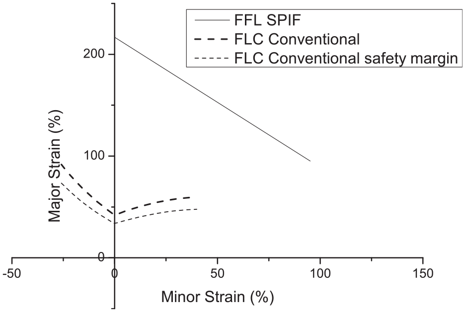
Fracture forming line.
Fracture forming limit can be enhanced using two forming tools as compared to SPIF process. 158 The fracture limit can also be improved with higher supporting tool force, tool shift and tool path strategy.
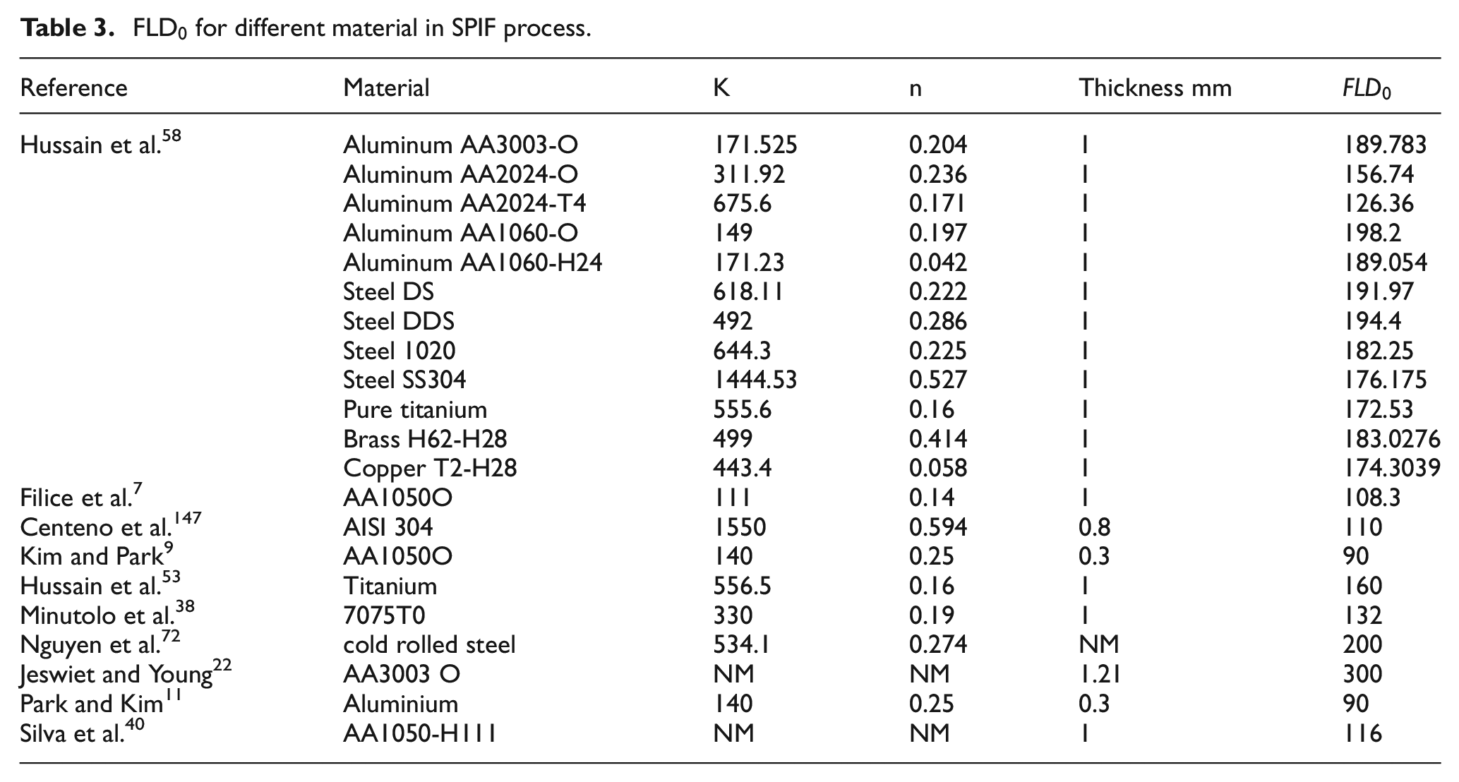
Plane strain intercept (FLD0) is also used as formability measure to compare the different materials and to judge the process capability. FLD0 for some of the materials is compiled and tabulated in the Table 3. In conventional FLC, FLD0 is the lowest point, however, in the ISF process FLD0 is the highest point of FFL. FLD0 in SPIF depends only on the percentage reduction in area and there is no influence of strain hardening exponent on FLD0.
58
In an experimental study performed by Ham & Jesweit,
33
it was reported that higher strains are produced while working on 5000 series aluminium alloy compared to 6000 series aluminium alloy. Lasunont and Knight
39
reported higher equivalent plastic strain in the SPIF process than TPIF process. Hence, formability was found to be better in TPIF process when producing the same type of component. Using stastical analysis and experimentation on range of materials Fratini et al.
13
observed that higher value of strain hardening exponent and percentage elongation leads to a larger value of FLD0 in the ISF process. Increasing the step-depth and reducing the tool diameter increases the stress concentration and hence leading to fracture and reduced formability (
FLD0 for different material in SPIF process.
Positive forming is found to be better than Negative forming because in positive forming plane strain mode is prevalent whereas in negative forming both plane strain and biaxial mode of deformation is present.
11
Summation of major strain and minor strain (
Forming time
Forming time measurement is important in the ISF process because higher forming time leads to higher energy consumption. Step-depth and forming feed has the maximum influence on the forming time as proved in a study based on Taguchi analysis by Sarraji et al. 91 No undesirable effect was found even at working feed rates of 5000 mm/min which greatly reduces the forming time. 162 The feature-based approach of tool path generation can reduce the forming time by 50% as compared to the constant z-depth approach of tool path generation for the same value of scallop height. 115 To reduce the forming time, hybrid process of stretch forming and ISF can also be used. 63 Ambrogio et al. 119 compared the time and energy required for high speed setup developed on CNC lathe and compared with the traditional setup for ISF on milling machine. The results of the test were promising and the time reduction from 420 s to 12 s and energy reduction from 1330 kJ to 130.6 kJ was achived from the experiments performed under identical conditions. Taherkhani et al. 172 used genetic algorithm approach to optimize the parameters in which three response variables were optimized using multiobjective optimization (Dimensional error, surface roughness and forming time). Optimal value of forming time was 1724 sas compared to the maximum value of 4134 s.
Hardness and grain size
The hardness of the formed component depends on the number of factors. In general hardness of the formed component increases as reported by Amino et al. 120 (from a range of HB40-HB50 to HB70-HB80 range). Study performed by Suresh et al. 161 shows that hardness of the component was found to be same as of base material (134 HV) in bending region, however, it was found to be increased in wall region (185 HV) and at the tail end (208 HV) of component. This was mainly attributed to grain elongation and strain hardening. Grain size was found to be increased from ASTM6 to ASTM5 number. Elongated grains were also observed at a distance away from the initial position. 92 Increasing the tool diameter, feed rate and speed tend to elongate the grain. 111 However, reverse phenomena was observed in the case of step-depth. In a study (AA2017-T3) 127 performed to learn the effect of rotational speed, hardness was found to be decreased due to an increase in grain size because of heat generation (250°C). In friction-stir assisted ISF process, no change in grain size (65 µm) was observed up to 4000rpm while forming a cone of 45° with AA6082-T6 aluminium alloy. 114 However, beyond 4000rpm due to dynamic recrystallization grain size reduces to 20 µm. Hardness was also observed to decrease from 103 HV to about 90 HV beyond 4000 rpm.
Summary and future scope
Over a period of time significant development have emerged in the equipment front to develop the ISF process. Initially CNC machines were used to perform the ISF process, however, the use of industrial robot either as individual equipment or in sync with other robot has improved the flexibility of the ISF process. Continuous development has also lead to the realization of commercial equipment dedicated to the ISF process. To the date only a single manufacturer (AMINO) has developed dedicated ISF machine. Studies 134 shows that total power consumption is highest in the AMINO machine as compared to conventional CNC machine and robot. Hence, the development of energy efficient dedicated machine is the need of the day to make the process economically viable for industrial application.
Most of the research work is addressing the Negative incremental forming with no die support i.e. SPIF process. The SPIF process has the benefit that it doesn’t require any complicated toolings for supporting the formed component and hence it is explored extensively by the researchers. Very few work is made on TPIF process with partial or full die support. It is found that formability is better in TPIF process, 11 which needs to be explored further. However, it requires support toolings dedicated to the component being formed. Ease of preparing these toolings at low cost will help the new window to open in the TPIF research.
Selection of suitable hybrid ISF process may lead to successful manufacturing of components with improved formability. Process variants like laser-assisted, electric heat-assisted, friction stir-assisted, ultrasonic-assisted ISF processes have emerged as a variant of the process which improves the performance measures. However, optimization of the process parameters and underlying mechanisms needs further investigation. Ultrasonic assisted forming has been developed recently (2015) and very few papers are addressing this process. It is found promising in improving surface finish, reducing springback and forming forces. It may be a solution for a high forming time in ISF process, which is limiting the application of ISF process in the industry.
Mostly hemispherical ended tool is used in the process, however, more detail comparison is required to be made with flat end tool and roller ball tool. Flat ended tool is found to reduce pillowing effect, hence, further experimental study with the flat ended tool is required to be performed. Different tool materials have been used in the ISF process. However, the effect of tool material on forming of different material of sheet metal blank is not studied. Adhesive wear was found to be the dominant mechanism of wear. 35 However, quantification of wear of tool and sheet metal blank in the ISF process still requires further study. Moreover, life of the tool in ISF process and its empirical prediction will help in enhancing the knowledge of the ISF process.
Different lubricants have been used by the researchers. However, the effectiveness of a particular lubricant to a specific material for the ISF process needs further investigation.
Use of optimum parameters (Geometry parameters of workpiece and tool, process parameters, tool path trajectory, tribological parameters) lead to better formability. Tool path is one of the important parameter which helps in controlling the thinning, geometric accuracy and formability in the ISF process. Ten different performance measures have been summarized in this paper which affects the acceptibility of the component formed by the ISF process. Optimization methods like Grey Relational Analysis, Box-behenken design with multiobjective optimization, genetic algorithm etc. helps in achieving good overall optimization of performance measures.
There is a contradiction in the literature about the effect of process parameters like tool diameter, step-depth and forming feed on the formability of the component. The reason for contradiction may the different processing material, thickness, frictional condition and process variant used for the performance of experiments. Moreover, these parameters might be having interaction effects on the performance measure.
The vertical wall is prepared using multistage forming strategies. 50 However, the formation of a true cylindrical shape without stepped feature at the bottom (created by rigid body motion) is the current issue to be solved.
Prediction of successful forming of the component in the ISF process can be done using fracture forming line (FFL) in conjunction with FE simulation to decrease the lead time. For the SPIF process strain based approach has been widely used to prepare the FFL. However, few work has been found reporting the use of stress based approach to prepare FFL of ISF process. Still, effect of various process parameters on FFL need to be established.
Different mechanisms have been proposed based on analytical and experimental findings and reveals the mode of deformation and enhanced formability in the ISF process. In the ISF process material deforms due to combined effects of stretching, bending, shear, contact stress and cyclic stress. However, the mechanism proposed for the ISF process simplifies the analysis by assuming the effect of one or the other as negligible. Hence, which mechanism is more effective in predicting the behaviour of the deformation in the ISF process is still remaining a matter of further comparative investigation based on common geometry, material and process parameters.
Experimental results available in the literature are mostly for a single size and shape of the component and hence cannot be generalized. Hence, further investigation is required considering the “size effect” to generalize the results.
Over a period of time the geometric accuracy, surface finish and the thickness which can be processed by the ISF process have been improved. Despite of that the industrial application of the ISF process is under scanner and limited to one piece production or small batch production. For industrial application of the ISF process, time of fabrication puts the hurdle and needs to be addressed.
In the SPIF process tooling cost is less, however, one of the important cost element in sheet metal industry is material utilization or yield. To the date none of the research paper has been found comparing the material yield in SPIF process with the other conventional processes. Detailed cost analysis of the SPIF process in comparison with other sheet metal forming process would help in selecting the appropriate process to form a particular shape and size of the component.
Footnotes
Appendix
All the tables related to materials used in the ISF process are kept here. It gives useful information regarding the process parameters used by the researchers and effect of parameters on the performance measures.
Declaration of conflicting interests
The author(s) declared no potential conflicts of interest with respect to the research, authorship, and/or publication of this article.
Funding
The author(s) received no financial support for the research, authorship, and/or publication of this article.