
Abstract
An investigation of the micro-channelling process on a quartz crystal using an abrasive slurry jet is presented. An experimental study is conducted first to understand the material removal process, surface quality as well as the effect of process parameters on the channelling performance, namely the material removal rate, channel depth, top channel width and channel wall inclination angle. It is found that a good micro-channel top edge appearance and bottom surface finish can be produced on quartz crystal by employing smaller particles with a relatively small jet impact angle, but at the sacrifice of material removal rate. Predictive models for material removal rate and micro-channel depth are then developed using a combination of the dimensional analysis method and the particle impact erosion theories, where the squeeze film effect on the impact erosion is considered. The models are verified experimentally and it is found that the model predictions are in good agreement with the corresponding experimental data.
Introduction
Quartz crystals have the special properties of piezoelectricity and find wide applications in resonators, oscillators, micro-sensors, actuators, frequency standards and so on,1,2 whose performance greatly depends on the quality of the manufactured micro-structures, like micro-channels and micro-holes, on the crystals. For high performance and reliability of the devices, these micro-structures need to be fabricated with no or minimum process-induced damages. However, the hard and brittle quartz crystals are considered as difficult-to-machine materials and an enabling technology is needed for fabricating micro-structures on the materials with good surface integrity and machining efficiency.
Abrasive slurry jet (ASJ) micro-machining3–7 is a relatively new processing technology with some distinct advantages of no thermal damages, high flexibility, high cutting rate and the ability of cutting almost any materials over the other machining technologies such as laser machining, electrical discharge machining and chemical machining.8–10 It gains particular favour in processing difficult-to-machine materials, 11 although more research is yet needed to bring this technology to commercial applications. In ASJ machining, abrasive particles are mixed usually with water to form an abrasive slurry, which is then increased to a high pressure of several to several tens of megapascals before going through a micro-sized nozzle to form an ASJ and impact the target surface to remove material by means of impact erosion. Miller 12 employed a slurry jet to cut micro-slots into thin and soft materials and demonstrated the ability of this technology for cutting micro-sized features. Wang et al. 4 and Pang et al.5–7 also demonstrated the capability of ASJ in performing micro-machining on brittle materials and revealed the erosion mechanisms in the material removal process. It has been found that this technology enables the machining of micro-holes and micro-channels to a desired depth on glasses. Viscous flow-induced ductile-mode erosion plays an important role in the micro-hole formation, and the holes are characterised by a W-shaped cross section, 4 although non-W-shaped holes were also reported in recent studies on brittle glasses.13,14 It was found that micro-channels formed suffered from severe waviness on the bottom surface, which was claimed mainly as a result of jet deflection and secondary viscous flow.5–7 It is thus necessary to improve the cut quality in ASJ micro-machining. Furthermore, while previous studies5–7 considered a host of process parameters, some other important parameters, such as the abrasive particle size and jet impact angle, which have been shown to have a significant effect on the meso-scale abrasive waterjet (AWJ) machining process,15–17 have yet to be studied in ASJ micro-machining.
In this article, an analysis of the ASJ micro-channelling process and the characteristics of the channels produced on a quartz crystal are presented based on an experimental investigation. The machined surface morphology and the micro-channelling performance in terms of material removal rate (MRR), channel depth, channel wall inclination angle and top channel width are discussed with respect to the operating parameters. Predictive models for the MRR and micro-channel depth are then developed and experimentally verified.
Experiment
The experiment was conducted with an in-house developed ASJ machining system, as shown in Figure 1. In this system, a pressurised air-driven pump was used to achieve a high water pressure. The pressurised water was then delivered into a high pressure tank where it squeezed a bladder containing premixed slurry and forced the slurry to flow into a nozzle and formed a micro-ASJ. The bladder was made of a waterproof soft material for isolating the slurry from the incoming water to control the abrasive concentration. A zirconium dioxide ceramic nozzle with an inner diameter of 0.125 and 10.5 mm in length was used through a nozzle holder. This nozzle aspect (length to diameter) ratio allowed the contraction coefficient of the jet to be considered as unity. 18 Three translation stages with the control resolution of 0.01 mm were used to move the nozzle or workpiece in the X, Y and Z directions. The detailed setup of the workpiece with the nozzle is shown in Figure 2, in which the nozzle standoff distance was defined as the distance between the nozzle exit and the target surface along the nozzle centre line, and the jet impact angle was defined as the angle between the nozzle centre line and the target surface.
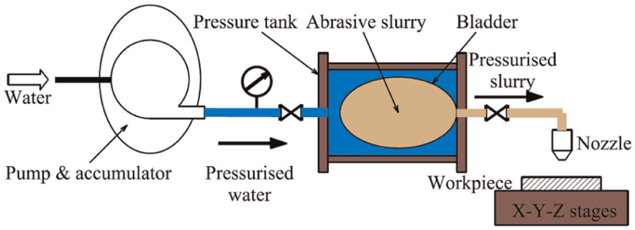
Schematic representation of experimental setup.
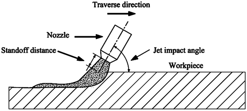
Nozzle and workpiece arrangement.
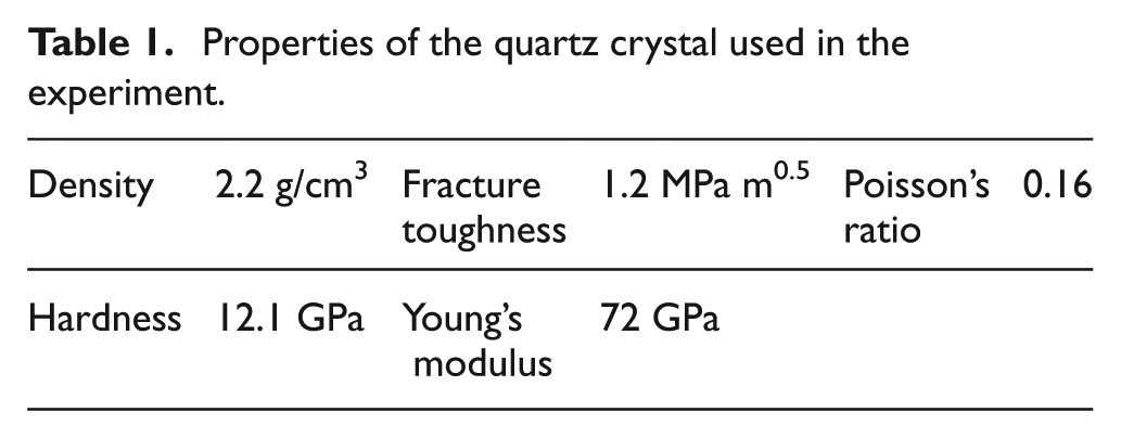
Due to its wide applications in electromechanical devices, a quartz crystal (from Zhejiang Crystal-Optech Co. Ltd, China) was used as the specimen material, whose major properties are given in Table 1. Silicon carbide (SiC) particles (30.5 GPa hardness and 3.2 g/cm3 density) with the average particle diameter of 10, 12, 15 and 18 µm were employed as the abrasive. The nozzle standoff distance was kept constant at 2 mm based on previous studies. 5 Since the jet impact angle is a significant factor in affecting the cutting quality in AWJ machining process, 17 four levels of backward jet impact angle at 45 °, 60 °, 75 ° and 90 ° (Figure 2) were selected. In addition, the water pressure, nozzle traverse speed and abrasive particle concentration were also considered at four levels, as given in Table 2.
Properties of the quartz crystal used in the experiment.
Operating parameters used in experimental design.
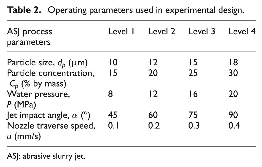
ASJ: abrasive slurry jet.
A Taguchi design of experiment with a standard L16 (44) orthogonal array was used for particle size, particle concentration, water pressure and jet impact angle. Each of the 16 combinations was tested under the four nozzle traverse speeds, resulting in 64 combinations. Additional 28 tests using the parameters given in Table 2 were also carried out to improve the data analysis as well as to obtain sufficient ‘as measured’ data for graphical presentation. Thus, a total of 92 tests for machining channels at 5 mm length were conducted for the study of micro-channelling performance and for model development. Furthermore, 30 model verification tests were performed to assess the adequacy of the developed models in section ‘Model assessment’. Each test was repeated at least three times and the data presented are in fact the average data.
The channel surface morphology was inspected using a Keyence VHX-100 three-dimensional (3D) digital microscope, while the channel characteristics (depth, top width and wall inclination angle) were obtained with the assistance of a Keyence VK-X200 3D laser measurement microscope. Furthermore, the surface roughness (centre line average Ra) was measured along the traverse direction with the Keyence VK-X200 3D laser measurement microscope with the cut-off wavelength of 0.8 mm. Four measurements of the cross-section profile for each channel were carried out and the average was taken.
Experimental results and discussion
Figure 3 shows a typical machined channel in a two-dimensional (2D) and 3D view as well as a cross-sectional profile. It exhibits a U-shaped profile characterised by a wider entry at the top, and the channel width reduces downwards, so that the channel walls incline by an angle, as shown in Figure 3(c). The channel depth was measured at the centre line, and the top channel width was defined using the intersection of a fitted straight line with the workpiece free surface. The straight line was obtained by linearly fitting six consecutive sidewall points of 2.5 µm apart from about a half of the depth upwards (Figure 3).
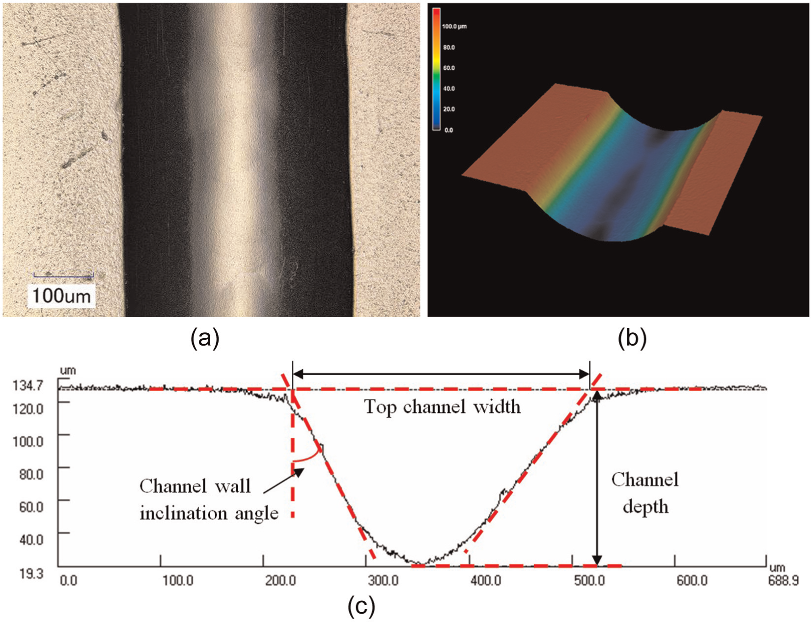
Micro-channel characteristics: (a) top view, (b) 3D view and (c) cross-sectional profile (dp = 12 µm, P = 16 MPa, Cp = 15%, α = 90° and u = 0.2 mm/s).
Earlier studies6,7 have indicated that the channel bottom surfaces machined by ASJ are characterised by a wavy pattern, and it was believed to be caused by jet deflection and the secondary viscous flow. It has further been found that the shaker used on the pressure tank in previous studies to minimise the deposition of particles in the slurry contributed to the fluctuation of the slurry pressure and hence contributed to the wave formation. As such, the experiment in this study was improved and the shaker was turned off during the test process. It was expected that during the short duration of each test (maximum of 50 s), particle setting would not cause a major concern in affecting the particle concentration. Furthermore, a backward jet impact angle was used to facilitate the scanning action of the particles so as to increase the surface quality, although it is understood that the use of a backward impact angle may be at the sacrifice of MRR. With this experimental setup, no large wavy pattern is discernible in this study, as shown in Figure 3(a) and (b).
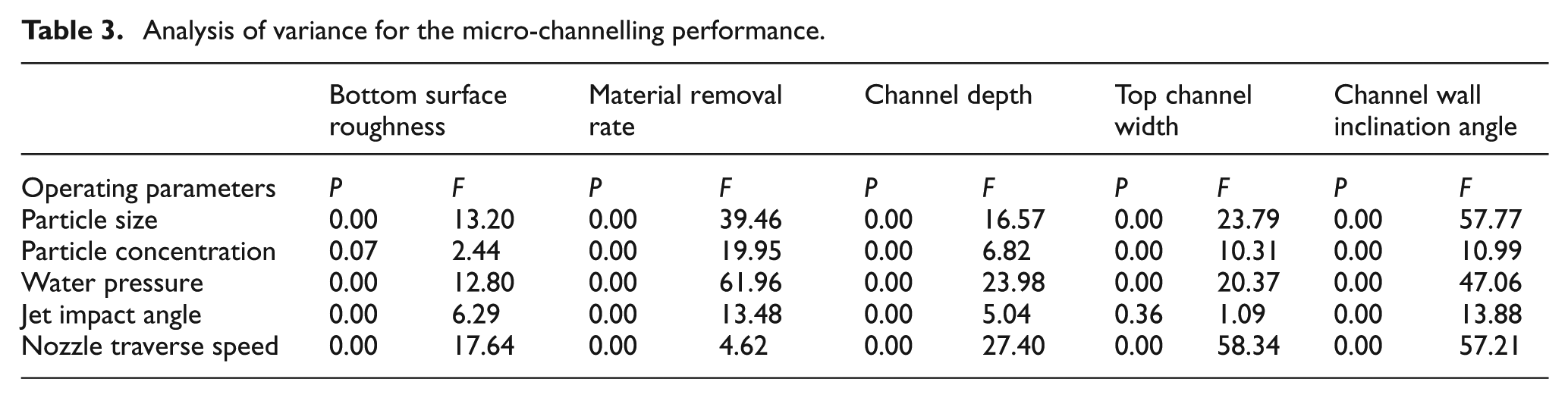
An analysis of variance (ANOVA) was conducted to identify the significance of the process parameters considered for the micro-channelling performance (channel bottom surface roughness, MRR, channel depth, top channel width and channel wall inclination angle), and Table 3 shows the ANOVA results. The P value reports the significance level and, since the analysis was carried out at 5% significance level, when the P value is less than 0.05, the effect of the respective factor is significant to the response variable. By contrast, the F value is the mean square error to residual, which is used to determine the effect size of a factor; for instance, the nozzle traverse speed has the highest F value and hence the largest effect on the bottom surface roughness. A detailed analysis of the effect of the process parameters on these performance measures is given in the following.
Analysis of variance for the micro-channelling performance.
Channel bottom surface roughness
An ANOVA was carried out in order to identify the process parameters that are significant in affecting the roughness of the channel bottom surfaces, as shown in Table 3. It has been found that the nozzle traverse speed has the most profound effect on the surface roughness, followed by particle size, water pressure and finally jet impact angle. The particle concentration has only a minor effect on the surface roughness. Figure 4(a) shows that increasing the water pressure caused the surface roughness to increase. This may be due to the fact that a higher water pressure results in a higher particle velocity and accordingly a higher particle energy that can cause larger craters on the surface by individual impacts and consequently forms a rougher surface. The roughness of the bottom surface gradually decreases by increasing the nozzle traverse speed, as shown in Figure 4(b). The reason may be that a higher traverse speed is able to remove only a thin layer of the work material from a polished surface, so that the surface formed is less rough than under a higher traverse speed where a larger depth of cut is generated by removing the material layer by layer with an accumulated and increased surface roughness. Figure 4(c) shows that an increase in the jet impact angle or particle size results in an increase in the bottom surface roughness. This may be due to the fact that a smaller impact angle gives more impact force tangent to the work surface, so that the erosion involves more cutting action to form a smoother surface. Likewise, since smaller particles carry less energy, the machined surface is formed by the cumulative effect of smaller craters generated by individual particles for a smoother surface.
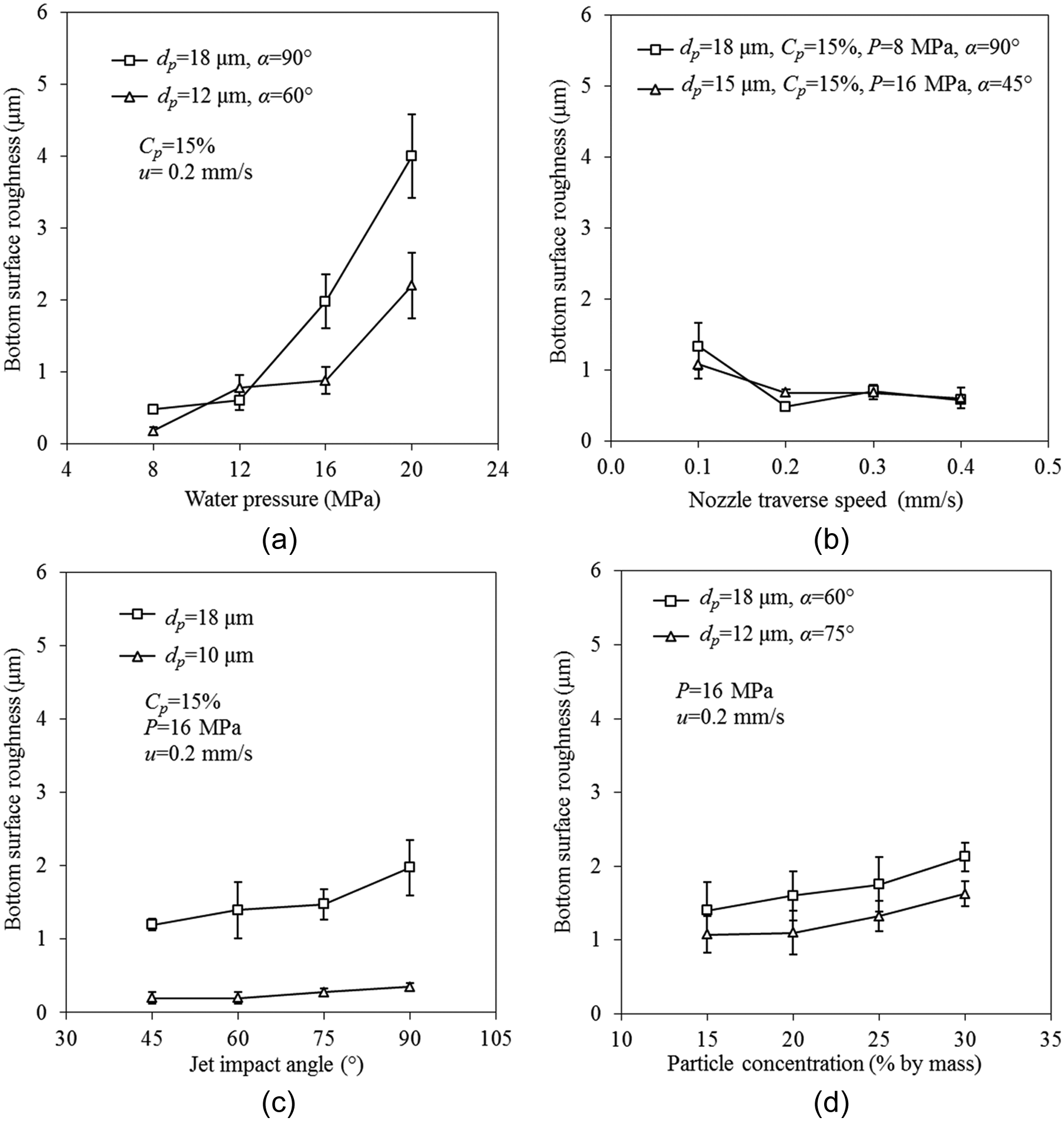
Effect of process parameters (a) water pressure, (b) nozzle traverse speed, (c) jet impact angle and particle size, and (d) particle concentration, on the bottom surface roughness (the scatter bars show the standard deviation).
Figure 4(d) shows that the bottom surface roughness increases slightly with an increase in particle concentration. This may be attributed to the increased depth by a higher abrasive concentration, which is associated with a rougher surface, as discussed above.
MRR
According to the ANOVA results in Table 3, water pressure plays the most important role in affecting the MRR, followed by particle size, particle concentration, jet impact angle and finally by nozzle traverse speed. Figure 5 shows the trends of MRR with respect to process variables. It shows that the MRR increases with an increase in the water pressure, jet impact angle, particle size and particle concentration in the slurry and decreases with an increase in nozzle traverse speed. MRR is primarily affected by the amount of kinetic energy brought into the process. This can be achieved by increasing the water pressure, increasing the particle concentration, which permits more particles to impacting the material, and using larger particles, which result in smaller deceleration rate after the particle leaves the nozzle exit so that particles with more energy impacts the material. All of the above can result in an increase in the MRR. Likewise, increasing jet impact angle facilitates brittle mode erosion for increasing the removal rate of brittle materials.19–21
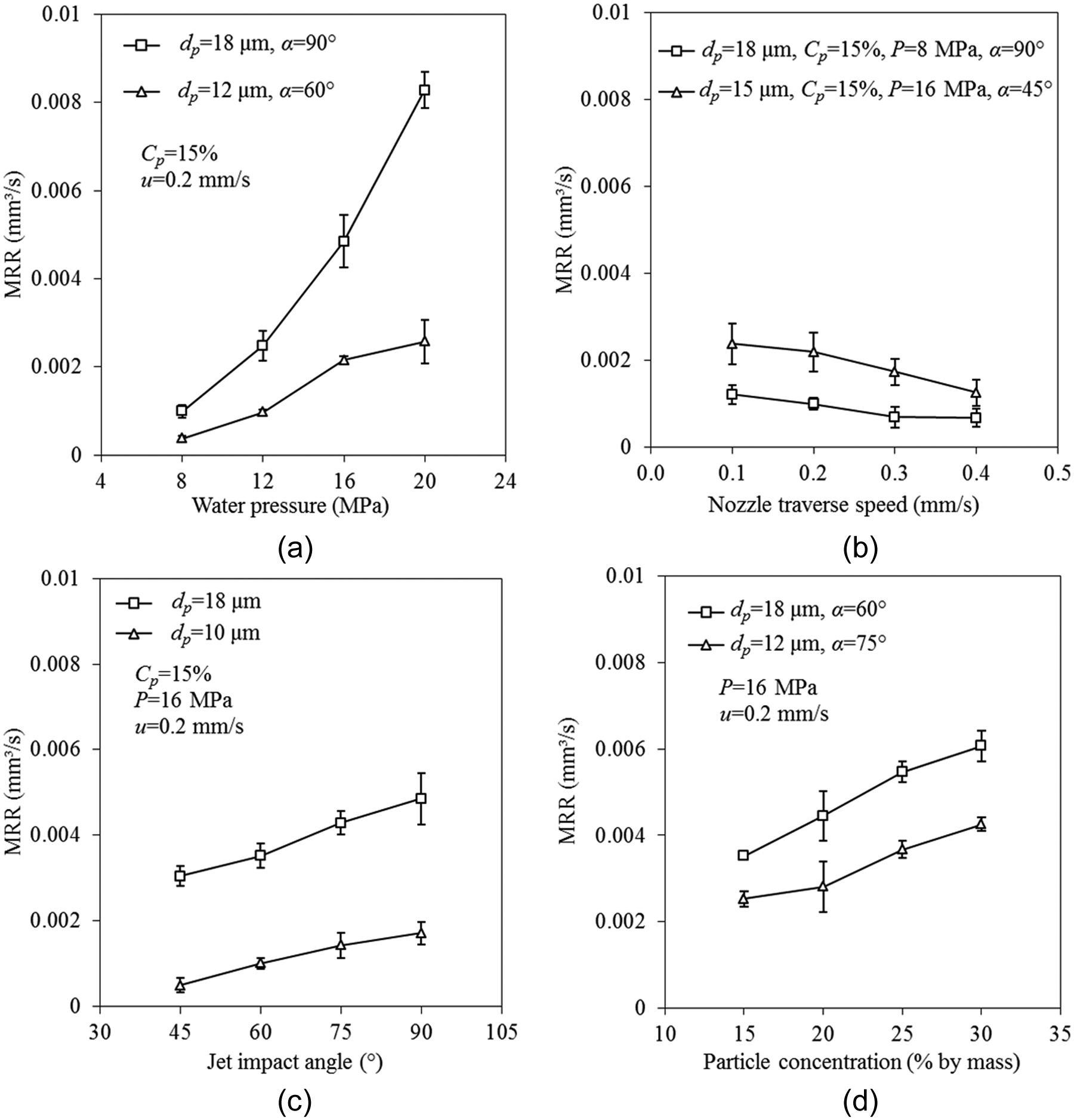
Effect of process parameters (a) water pressure, (b) nozzle traverse speed, (c) jet impact angle and particle size, and (d) particle concentration, on the MRR (the scatter bars show the standard deviation).
It may be intuitively believed that the nozzle traverse speed does not affect the MRR while a reduction in the traverse speed may even reduce the MRR due to the increased interference between particles. However, in ASJ machining, a thin water layer on the work surface may cause a shielding effect on the cutting efficiency of the impacting particles, and this effect is manifested at higher nozzle traverse speeds where the jet more quickly approaches and impacts a new work surface with water film. As such, the MRR shows a slight decreasing trend with an increase in the nozzle traverse speed (Figure 5(b)).
Channel depth
The statistical analysis in Table 3 shows that the nozzle traverse speed has the most significant effect on channel depth, followed by water pressure, abrasive size, abrasive concentration and finally the jet impact angle. The channel depth shows an increasing trend with an increase in water pressure, abrasive size, abrasive concentration and jet impact angle, as shown in Figure 6(a), (c) and (d). An increase in the water pressure, abrasive size and abrasive concentration allows more jet energy to be brought into the cutting process after travelling a short standoff distance and therefore results in an increased channel depth. Likewise, an increase in the jet impact angle is preferred for brittle mode material removal, which increases the erosion rate.19–21 By contrast, the channel depth decreases with an increase in nozzle traverse speed, as shown in Figure 6(b). This is mainly due to the fact that a faster passing jet under a higher traverse speed allows less jet-material interaction time, which yields a smaller channel depth.
Effect of process parameters (a) water pressure, (b) nozzle traverse speed, (c) jet impact angle and particle size, and (d) particle concentration, on the channel depth (the scatter bars show the standard deviation).
Top channel width
The primary variables affecting the top channel width are, in order of significance from the most to the least, the nozzle traverse speed, particle size, water pressure and abrasive particle concentration, according to the ANOVA results in Table 3. It is known that the effective jet diameter is a key factor determining the top channel width. 22 The increase of water pressure results in an increase in the dynamic pressure within the jet, which gives an increase in the effective jet diameter, and hence opens a wider channel, as shown in Figure 7(a). Figure 7(b) shows a negative effect of nozzle traverse speed on the top channel width. It may be explained that a fast nozzle traverse speed allows less abrasive particles to strike on a given area on the target, generating a narrow slot. It is noted that the effect of jet impact angle is not significant with the P value larger than 0.05, as shown in Table 3. This may be attributed to the fact that the standoff distance was kept constant in the experiment, so that there was not any significant change to the interaction of the jet with the target surface and hence caused little change to the top channel width. By contrast, an increase in the particle size leads to a decrease in the top channel width, as shown in Figure 7(c). This may be due to the fact that small particles with less energy have a greater tendency to follow the diverging water stream than the larger ones, resulting in a larger particle jet divergence angle 23 and a wider channel. It can be seen from Figure 7(d) that an increase in particle concentration results in a slight increase in the top channel width. This is because a higher particle concentration allows more particles to strike on the target and opens a wider slot. Furthermore, it is interesting to note that the rate of increase of the top channel width reduces as abrasive particle concentration increases to beyond a certain value. This is possibly caused by the increased interference between particles as the particle concentration increases, which reduces the overall cutting efficiency of particles.
Effect of process parameters (a) water pressure, (b) nozzle traverse speed, (c) jet impact angle and particle size, and (d) particle concentration, on the top channel width (the scatter bars show the standard deviation).
Channel wall inclination angle
Figure 7(a)–(d) shows that the channel wall inclination angle decreases with an increase in water pressure, particle size, particle concentration and jet impact angle, but increases with nozzle traverse speed. Unlike in the ultrahigh pressure AWJ cutting, the secondary cutting process of the abrasive particles in the viscous flow in the lower pressure case plays a relatively significant role.4–7 An increase in kinetic energy in the viscous flow from a higher water pressure provides more energy to the turbulent flow, which drives the abrasive particles to remove more materials from the lower part of the channel, thus decreasing the channel wall inclination angle, as illustrated in Figure 8(a). Figure 8(b) shows that an increase in nozzle traverse speed increases the channel wall angle. A faster travelling jet reduces the interaction between the jet and target and the number of abrasive particles to impact a given area in the lower portion of the channel, which increases the channel wall inclination angle. As shown in Figure 8(c), an increase in particle size and jet impact angle facilitates brittle mode erosion that enables an effective jet-cutting action even at the low region of the channel, thus creating a steeper channel wall. Likewise, increasing the particle concentration allows a large number of energy-carrying particles to strike on the target material and decreases the channel wall inclination angle.
Effect of process parameters (a) water pressure, (b) nozzle traverse speed, (c) jet impact angle and particle size, and (d) particle concentration, on the channel wall inclination angle (the scatter bars show the standard deviation).
Model development
MRR
Material removal in ASJ machining can be regarded as the accumulation of material removed by individual particles. However, not all the particles inside an ASJ actually contribute to material removal; some may not even have sufficient energy to remove the material.11,24 An efficiency factor (εp) can be introduced to account for this effect, so that the MRR may be expressed as
where np is the number of abrasive particles supplied per unit time, which can be found from the abrasive mass flow rate ma, and the average mass of a single particle mp, and Vs is the average volume of material removed by an impacting particle.
Assuming that the shape of abrasive particles is spherical and the particle size distribution is uniform, the average mass of a particle can be calculated from
where dp is the average particle diameter, and ρp is the abrasive particle density. Thus, equation (1) becomes
It is now necessary to model the material removal by a particle impact (Vs).
Material removed by a particle impact
In AWJ machining, the material removed by individual particles may be considered to be governed by the characteristics of abrasive particle, the particle impact parameters as well as the properties of target material. 11 The secondary material removal by the viscous flow may also need to be considered in the lower pressure micro-machining.4–7 It has been found that dimensional analysis 25 is a more powerful analytical technique in relating engineering quantities to the influencing variables than the theoretical or empirical modelling approaches. It is employed to model the material removed by a single particle impact in this study.
From the erosion theories, 26 the impact-induced erosion may be considered as a function of the kinetic energy possessed by a particle, that is, particle diameter, dp, density, ρp, particle velocity, vp, impact angle, αp and the target material properties. The ratio of material hardness to material fracture toughness (Hm/KIc) has been found to provide a useful measure for the brittleness of brittle material 26 and hence its effect on the erosion, while Zeng and Kim 27 used the ratio of target material hardness to its modulus of elasticity (Hm/Em) in their modelling work on the AWJ machining of ceramics and showed good results. To generalise these findings, material hardness, fracture toughness and modulus of elasticity are considered in this study. It may be noted that the quantities discussed above also determine the secondary material removal process by the viscous flow, noting that the particle velocity is related to water pressure. Thus, the material removal by single particle impact may be expressed as
Using the Pi theorem in dimensional analysis 25 and by selecting dp, vp and Hm as the three repeating variables, noting that αp is already a dimensionless variable, equation (4) can be written as a function of five dimensionless Pi groups as
By applying the power-law formulation to equation (5), the volume of material removal by a particle can be given by
where k1, a1, a2, a3 and a4 are dimensionless coefficients. In this equation, the particle impact angle, αp, and the abrasive particle velocity, vp, need to be determined.
Particle impact angle
In ASJ micro-machining, the particle impact angle may be affected by the dynamic behaviour of the slurry jet at the point of impact, the geometrical characteristics of the target material surface being eroded and some process parameters such as the jet impact angle (α) and nozzle traverse speed (u),17,28 noting that standoff distance was kept constant in this study. All these effects can be attributed to the process parameters, including particle diameter (dp), density (ρp), velocity (vp) and abrasive concentration (Cp) in slurry jet, and the material properties are represented by fracture toughness (KIc), hardness (Hm) and modulus of elasticity (Em), as discussed earlier. Consequently, the average particle impact angle, αp, can be expressed as
Similarly, dp, vp and Hm are selected as the repeating variables in the dimensional analysis, and using the power-law formulation, the average particle impact angle αp can be given by
where k2, b1, b2, b3, b4, b5 and b6 are coefficients.
Particle velocity
Particles in ASJ are premixed thoroughly before the micro-ASJ is formed, so that particles are assumed to be distributed uniformly in the slurry and possess the same velocity as the surrounding water at the nozzle exit. Within a small standoff distance, it is believed that the velocity variation from the nozzle exit to the target surface is negligible. 5 Thus, the slurry jet velocity (vj) and the abrasive particle velocity (vp) can be obtained from Bernoulli’s equation, that is
where P is the water pressure, ρs is the mixed slurry density, and γ is the overall coefficient of discharge that characterises the momentum losses due to wall friction, fluid flow disturbances and compressibility of water. 29 With a given abrasive particle concentration (Cp), using the law of mass conservation and Archimedes’ law, 30 the slurry density can be given by
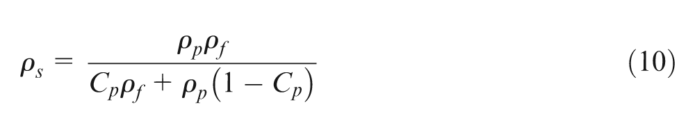
where ρf is the fluid density that is the water density in this study.
Squeeze film effect
A thin layer of water, called squeeze film, forms in the stagnation zone on the target surface and acts as a damping layer to resist the ASJ impacting on the target.
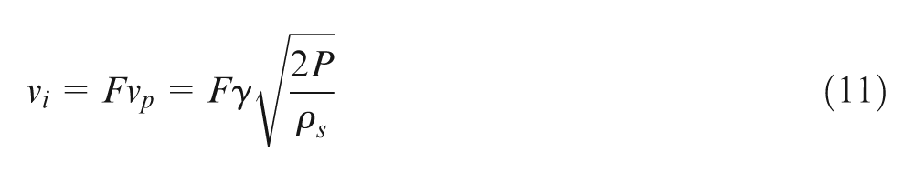
It has been found31–34 that the squeeze film intervening between an erodent particle and a target surface leads to a significant retardation of particle velocity immediately before impacting the target. In order to account for this effect, it is suggested that a correction factor F, which is dependent on the particle Reynolds number in the slurry jet and particle size, density and velocity, be applied to the particle impact velocity calculated from the potential flow analysis, so that the particle impact velocity, vi, passing through the squeezing film can be found from
Model for MRR
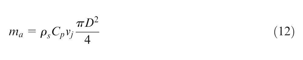
With a given particle concentration (Cp), the slurry jet velocity (vj) and nozzle inner diameter (D), the abrasive mass flow rate, ma, can be expressed as
Consequently, substituting equations (6), (8), (11) and (12) into equation (3) results in
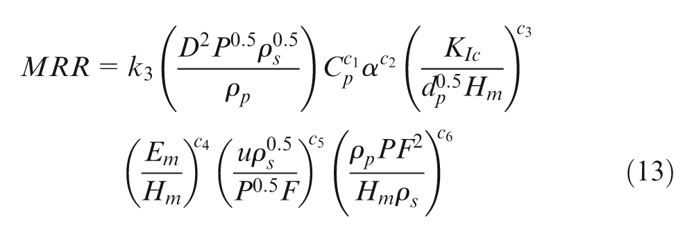
where k3, c1, c2, c3, c4, c5 and c6 are introduced to generalise all coefficients in the previous equations and can be determined by experimental data.
Channel depth
Figure 3(c) shows that the cross-sectional profile of a machined channel is similar to a cosine function curve, such that the channel depth (h) at any position can be approximated by a cosine function, as shown in Figure 9, that is
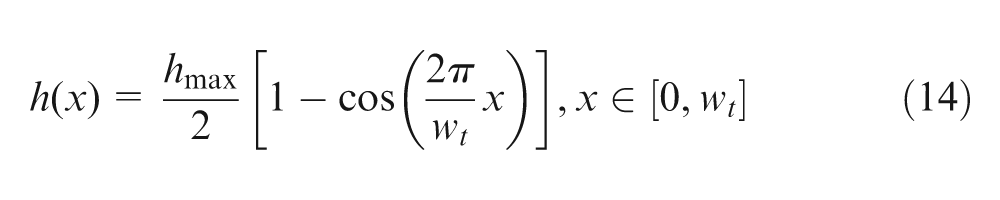
where hmax is the maximum channel depth and wt is the top channel width. When x = wt/2, h = hmax.
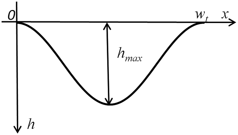
Schematic representation of the cross-sectional profile
Thus, the total area (S) between the curve of h(x) and the x axis is expressed by
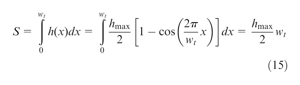
By ignoring the variation of profile area along the traverse direction, the MRR is given by
Consequently, by substituting equation (15) into equation (16), the maximum channel depth can be given by
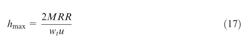
where the top channel width (wt) can be determined by a regression analysis of experimental data, and MRR can be found from equation (13).
Model assessment
Before the developed models can be used for predicting the micro-channelling performance, the coefficients need to be determined first. For this purpose, the experimental data from 92 tests stated under section ‘Experiment’ were employed to find the coefficients in equation (13) by regression analysis at a 95% confidence level, so that equation (13) for the experimental conditions used in this study becomes
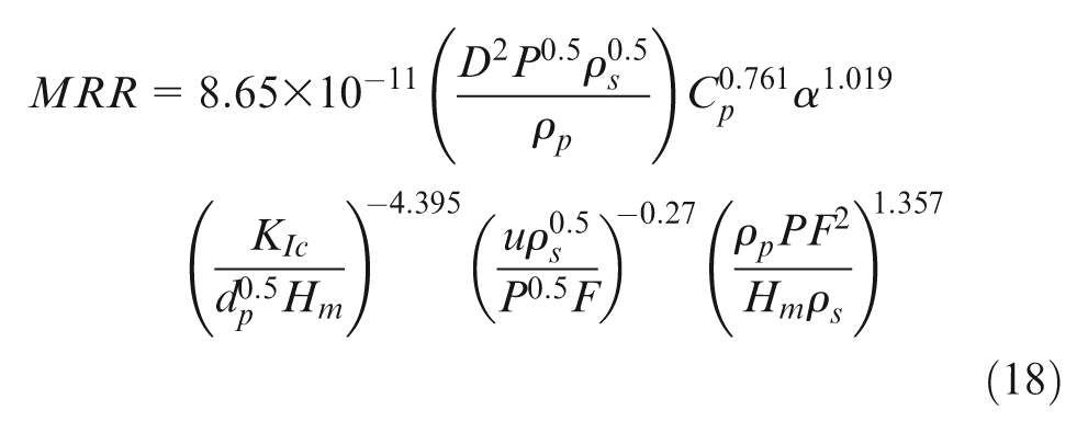
Substituting the nozzle inner diameter, material properties and abrasive properties relevant to this study into equation (18) give
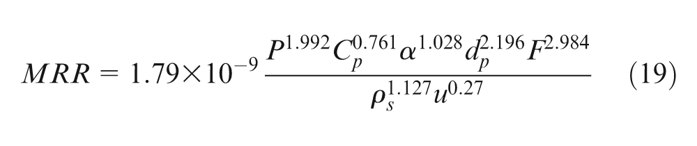
where the units of each parameter are given in Appendix 1.
To predict channel depth from equation (17), the top channel width was obtained from a regression analysis using the 92 sets of test data, namely
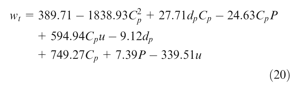
where the units of each parameter are given in Appendix 1. This regression model gives an 82% coefficient of determination (R 2 ) and is believed to be adequate for evaluating the top channel width.
In order to assess the developed models, additional 30 model verification tests were conducted, and the experimental data are compared with the model predicted MRR and maximum channel depth under corresponding conditions for the plausibility and adequacy of the models. These are shown in Figure 10, where the lines represent the predicted values while the symbols are for the experimental data. It can be seen that model predictions for both MRR and maximum channel depth agree well with the experimental data and correctly represent the trends of these two performance measures with respect to the process variables.
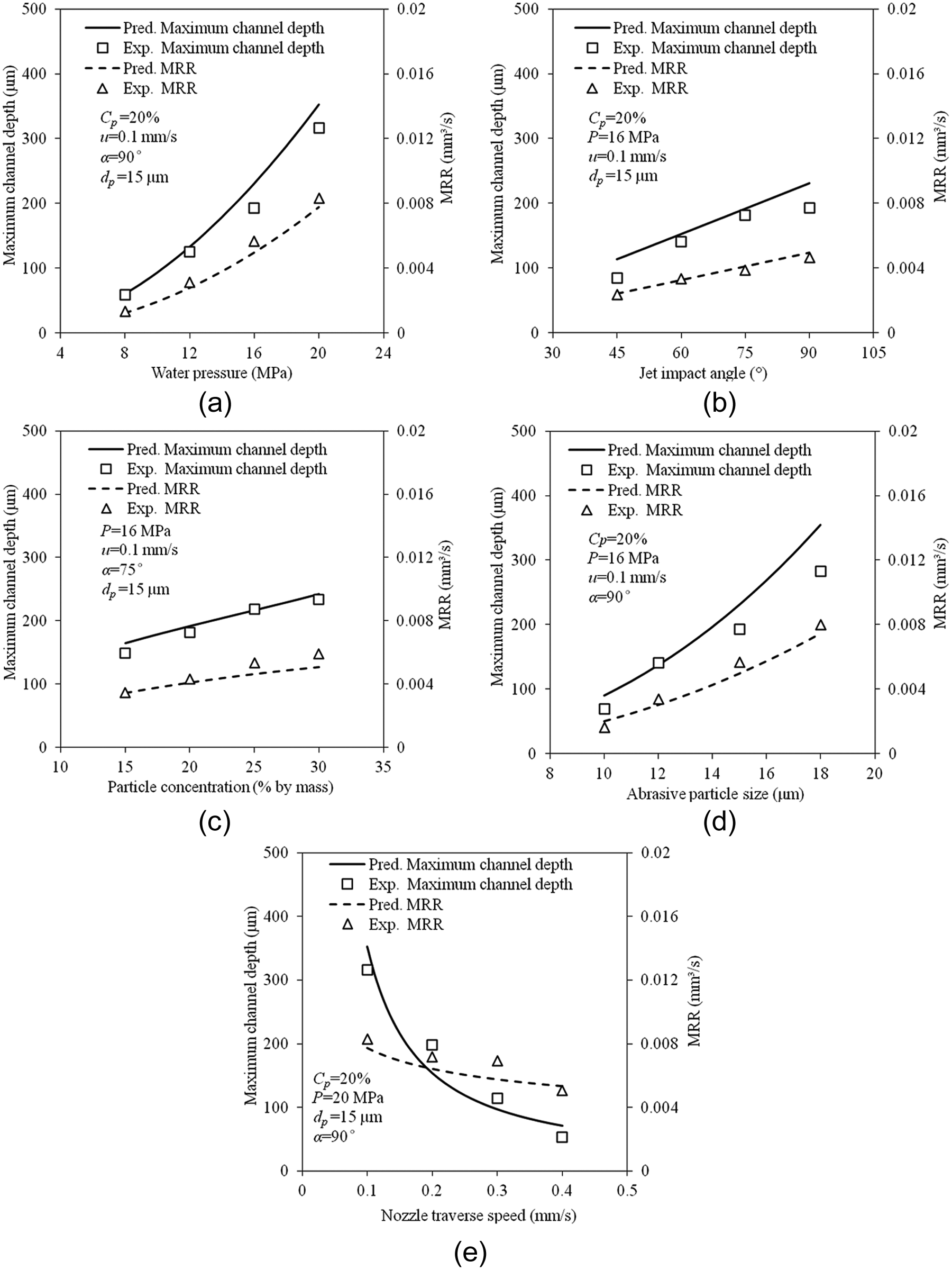
Comparison between predicted and experimental MRR and maximum channel depth with respect to process parameters, (a) water pressure, (b) jet impact angle, (c) particle concentration, (d) particle size, and (e) nozzle traverse speed.
A quantitative comparison shows that the percentage deviation of the predicted MRR is −5.47% on average with the standard deviation of 14.85%, while the average and standard deviations of the predicted maximum channel depths from the corresponding experimental data are 4.63% and 19.14%, respectively. Thus, it may be stated that developed models can give adequate predictions of these two quantities in ASJ micro-channelling on quartz crystal within the ranges of the variables considered in this study.
Conclusion
A study of the ASJ micro-machining process has been presented when fabricating micro-channels on quartz crystal used extensively in electromechanical devices. It has been found that good surface quality without large wavy patterns can be generated by employing smaller abrasives with a relatively small impact angles. Plausible trends of the bottom surface roughness, MRR, channel depth, channel width and channel wall inclination angle with respect to the process variables have been discussed. It has been shown that the bottom surface roughness increases with an increase in water pressure, particle size, jet impact angle and particle concentration, but decreases with an increase in nozzle traverse speed. It was shown that MRR and channel depth increase with the water pressure, jet impact angle, particle size and particle concentration, but decrease with an increase in nozzle traverse speed. The top kerf width decreases with an increase in nozzle traverse speed, jet impact angle and particle size, but increases with water pressure and particle concentration. By contrast, the channel wall inclination angle increases with nozzle traverse speed, but decreases with an increase of all the other variables. Based on the conditions considered, a combination of high water pressure and particle concentration, large abrasive particles and jet impact angle, and low nozzle traverse speed is recommended to maximise the MRR and channel depth, while a combination of low water pressure and particle concentration, small abrasive particles and jet impact angle, and fast nozzle traverse speed is recommended to minimise the surface roughness, which may be at the sacrifice of MRR and channel depth. For process control and planning, predictive models for MRR, top channel width and maximum channel depth have been developed and experimentally verified. It has been shown that model predictions are in good agreement with the corresponding experimental data with the average errors of about 5%.
Footnotes
Appendix 1
Declaration of conflicting interests
The authors declare that there is no conflict of interest.
Funding
The project was financially supported by the Australian Research Council (ARC) under the Discovery-Projects scheme. Huan Qi would like to thank the China Scholarship Council for providing a scholarship.