
Abstract
TC21 alloy is a new alpha–beta damage tolerance titanium alloy with high strength and high toughness. Little work has been done in the field of machinability analysis since this alloy was developed. The cutting forces and tool wear in high-speed milling of TC21 alloy with physical vapor deposition ((Ti, Al)N-TiN)-coated carbide tools under different cutting conditions were investigated in this article. The results showed that the cutting force component F x was more dominant of the three components, and the cutting forces presented an increasing trend with the tool wear progress, which in turn deteriorated the cutting condition and accelerated the tool failure progress. The major tool wear modes in high-speed side-milling TC21 alloy with coated carbide were adhesion and chipping on the rake face along with chipping and transverse crack on the flank face. Moreover, there was obvious nose depression from both the rake face and the flank face. Chipping along the flank and rake faces was identified as the main factor responsible for the failure of the coated carbide tools during the milling of titanium alloy TC21.
Introduction
Titanium and its alloys have found wide applications in the aerospace, biomedical and automotive industries owing to their good strength-to-weight ratio, the ability to retain high strength at elevated temperature and resistance to oxidation and corrosion. One of the very popular titanium alloys for these applications is Ti-6Al-4V, which compromises about 45%–60% of the total titanium products in practical use.1,2 In order to meet the design and application requirements for large size, high efficiency of weight saving, long life and low cost in new airplanes, a new class of titanium alloys based on the design of damage tolerance was developed. TC21 alloy, developed by Northwest Institute for Non-ferrous Metal Research (China) with intellectual property, is a damage-tolerant titanium alloy, and the nominal composition of the alloy is Ti-6Al-2Sn-2Zr-3Mo-1Cr-2Nb-Si. Recent investigations3,4 have proved that mechanical properties of TC21 alloy are superior to Ti-6Al-4V alloys owing to its higher strength, higher fracture toughness, lower crack propagation rate and outstanding welding performance. TC21 has been used in aviation and astronavigation industries.
During machining of titanium alloys, the combination of high temperature strength, low thermal conductivity and high chemical affinity for tool materials contributes to their poor machinability, and machining titanium alloy at higher cutting speed will cause rapid tool wear. 5 Thus, intensive research on the cutting performance of titanium alloys such as cutting temperature, cutting force, tool wear and chip morphologies has been published until now.6–17 Most studies focus on Ti-6Al-4V. Being a damage-tolerant titanium alloy, TC21 alloy has been employed as a structural for aircraft applications because of its specific strength and fracture toughness. The research efforts to date for TC21 alloy have mainly been focused on heat treatment, microstructure, mechanical properties, high temperature behavior and superplasticity.18,19 However, little work has been done on the cutting performance of TC21 alloy. The aim of this study is to investigate and analyze the effects of milling parameters and tool wear status on cutting force, and tool life to guide the production when machining titanium alloy TC21.
Experimental details
The workpiece material TC21 is a two-phase (α + β) titanium alloy. The chemical composition and mechanical properties of the material are given in Tables 1 and 2, respectively. The workpiece material throughout the experimental study was prepared in the form of 100 × 80 × 20 mm rectangular block.
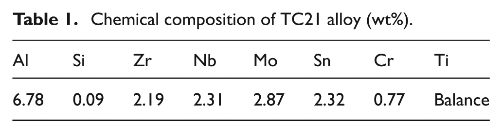
Chemical composition of TC21 alloy (wt%).
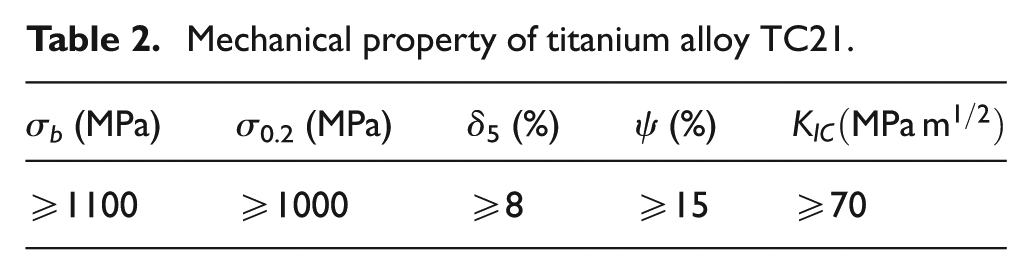
Mechanical property of titanium alloy TC21.
A Seco milling cutter with a coated carbide insert was used in the side-milling experiments. Table 3 describes the details of the tooling system.
Details of the tooling system.
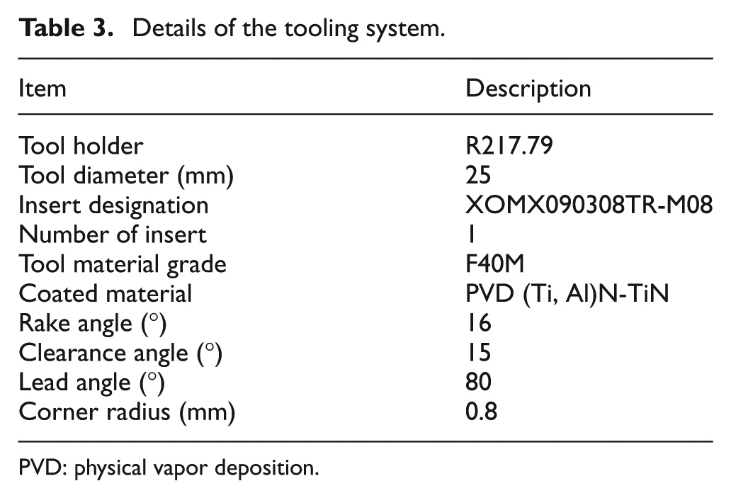
PVD: physical vapor deposition.
As shown in Figure 1, the machine used for the milling tests was a three-axis computer numerical control (CNC) vertical machining center (ACE-V500; Daewoo, Korea), equipped with variable spindle speed from 80 to 10,000 r/min and a 15-kW motor drive.
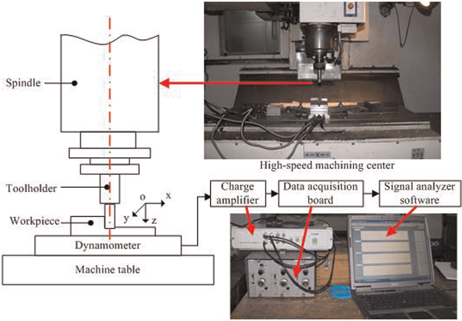
Experimental setup.
A Kistler-type 9257B dynamometer was mounted on machine table to measure the cutting forces, and the instantaneous cutting force components in x, y and z directions, Fx, Fy and Fz, were recorded down through a type 2825A-02 DynoWare signal analyzer software after amplified using a type 5070A multichannel charge amplifier. The dynamometer/charge amplifier and signal analyzer software mentioned above are produced by Kistler company in Switzerland. The average of the five peak values was used in the cutting force analysis. The workpiece was mounted on the dynamometer through a specially designed fixture.
The cutting parameters used in the experiment for cutting force measurement are given in Table 4. Since tool wear is the most important factor limiting tool life, tool wear was measured with a toolmaker’s microscope after a specific machining time period. The 0.3-mm average flank wear (VB) and 0.5-mm maximal flank wear (VBmax) are adopted in the experiment as tool wear criteria according to the standard ISO 8688-2:1989. 20 The dominant failure modes were observed using scanning electron microscope (SEM) method, and wear mechanism analysis was carried out according to SEM images.
Cutting parameters used in the milling tests.
A type of down-milling operation and a dry cutting environment were used for the machining tests. The cutting tool moves along the y direction and the cutting distance of each pass was 80 mm. At the beginning of the experiment, a new tool insert was mounted onto the tool holder. The high-speed side-milling test was interrupted at regular interval of five cutting passes to study the mode of the tool wear.
Experimental results and discussion
Cutting forces
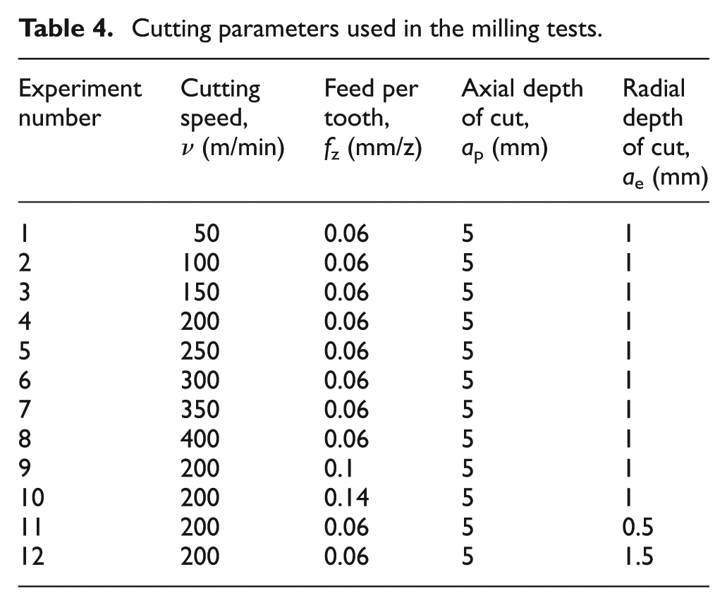
Cutting force is one of the significant physical variables, which have an intimate correlation with the tool wear and tool life. Figure 2 shows the cutting force waveforms in the first cutting pass. The chip thickness fluctuations over a revolution result in periodical changes in the cutting forces with the entry/exit of the cutting tooth. It is obvious that the cutting force component in the negative x direction displays significantly higher magnitudes than that of the other two components in y and z directions. So in the following discussion, Fx is used as the main cutting force component to investigate the relations between cutting force variable and tool wear.
Cutting force waveforms in the first cutting pass (sharp tool) (v = 50 m/min, fz = 0.06 mm/z, ap = 5 mm and ae = 1 mm).
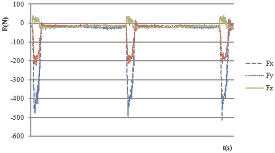
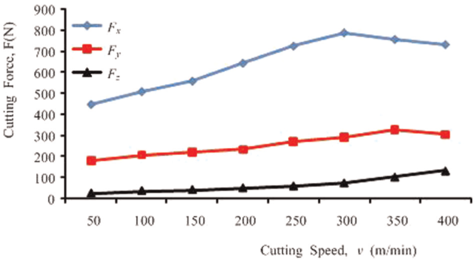
Cutting forces were detected during milling under different cutting parameters. Figures 3–5 show the effects of the milling parameters on three cutting forces. As shown in Figure 3, with the increase in cutting speed, the forces Fy and Fz increase a little, while Fx increases significantly when v = 50–300 m/min and then decreases slightly when v exceeds 300 m/min. On one hand, increasing the cutting speed increases the degree of strain hardening of workpiece materials and thus increases the deformation resistance of shear area. On the other hand, increasing the cutting speed generates higher temperature, which causes the workpiece material softening and decreases the cutting force. The influence of cutting speed on cutting force depends on comprehensive action of two aspects mentioned above. At the lower cutting speed, influence of strain and strain rate of reinforcement on cutting force is greater than the thermal softening, which result in increasing trend of the cutting force. When v exceeds 300 m/min, the thermal softening of workpiece materials caused by raised temperature dominated the effect on cutting force and thus leads to decrease in cutting force slightly. From Figures 4 and 5, it can be seen that all the three cutting forces increase with the increase in feed per tooth (fz) and radial cutting depth (ae), which should be caused by the increase in removal rates. The cutting forces when milling different workpiece materials are shown in Figure 6. The results showed that the cutting forces when milling TC21 are obviously higher than that when milling TC4. It means that TC21 is more difficult to cut than TC4, and the more stringent requirements on the tool for TC21 were put forward.
Effect of cutting speed on cutting force (fz = 0.06 mm/z, ap = 5 mm and ae = 1 mm).
Effect of feed per tooth on cutting force (v = 200 m/min, ap = 1 mm and ae = 5 mm).
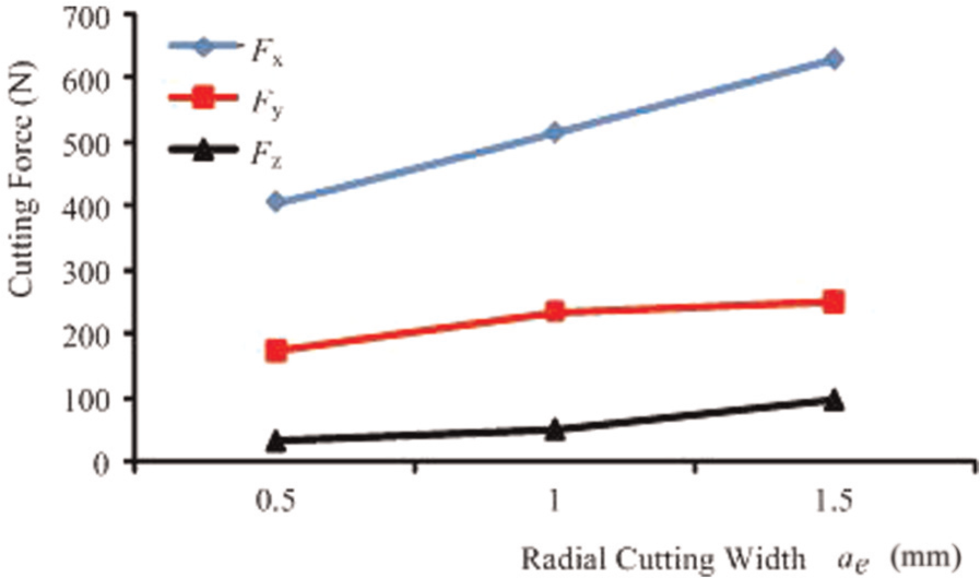
Effect of radial cutting depth on cutting force (v = 200 m/min, ap = 1 mm and fz = 0.06 mm/z).
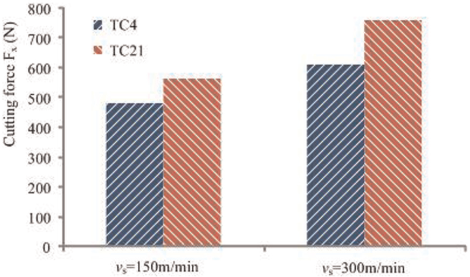
Cutting forces when milling different workpiece materials (fz = 0.06 mm/z, ap = 5 mm and ae = 1 mm).
Correlation between cutting force variation and tool wear progress
In addition to the cutting force variation under different cutting conditions, a time-dependent investigation of maximum cutting force over total length is analyzed. Figure 7 clearly illustrates how the cutting force (peak values) varies with cutting length. As shown in Figure 7, with the increase in the cutting time and tool wear, the cutting forces measured showed an overall tendency to increase. When side milling is performed in the first cutting pass, the tool edge is very sharp, and there is no significant tool wear. However, the cutting tool wears gradually as it is used and the cutting geometry continually changes as the tool wear progresses. Total forces are the sum of forces due to the chip formation and forces due to the tool wear. Therefore, the cutting forces increase with the progression of the tool wear, that is to say, tool wear contributes to the variation of the cutting forces.
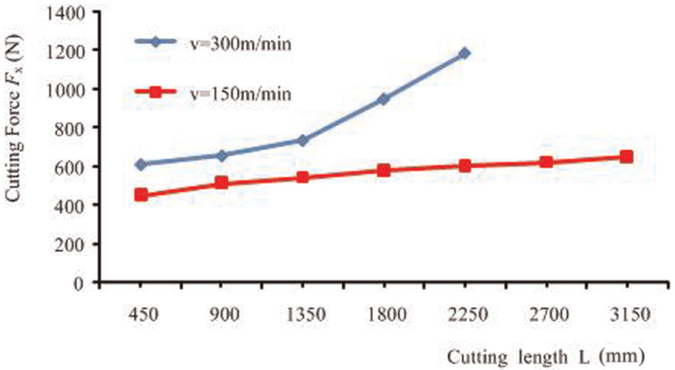
Variation of cutting forces (peak values of Fx) versus cutting length (fz = 0.06 mm/z, ap = 1 mm and ae = 5 mm).
Figure 8 shows the progression of average flank wear versus cutting length. With the increase in the cutting length, the average flank wear of the cutting tool increased gradually. It is obvious that the increase in cutting speed accelerated the progression of tool wear. In this study, the tool life was found to decrease with increasing cutting speed. A long tool life of about 28 min was achieved when machining at a cutting speed of 150 m/min, whereas the tool life was less than 9 min when machining at 300 m/min. The tool life decreased drastically when the cutting speed exceeded 300m/min. Moreover, the cutting force measured at the end of the tool life is almost twice the cutting force obtained using a sharp cutting tool edge when v is 300 m/min (as shown in Figure 7).
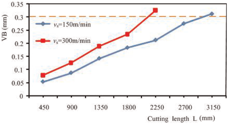
Progression of average flank wear versus cutting length (fz = 0.06 mm/z, ap = 1 mm and ae = 5 mm).
Figure 9 shows the failure history of coated carbide insert when the cutting speed is 300 m/min, and both the rake face and the flank face of the insert were presented after machining for a certain length. From these figures, microchipping on the rake face can be observed after machining for a certain length, and the cutting edge in the flank face showed a slow wear progression. Along with the cutting process, the chipping on both the rake face and the flank wear intensifies gradually until the cutting edge fails.
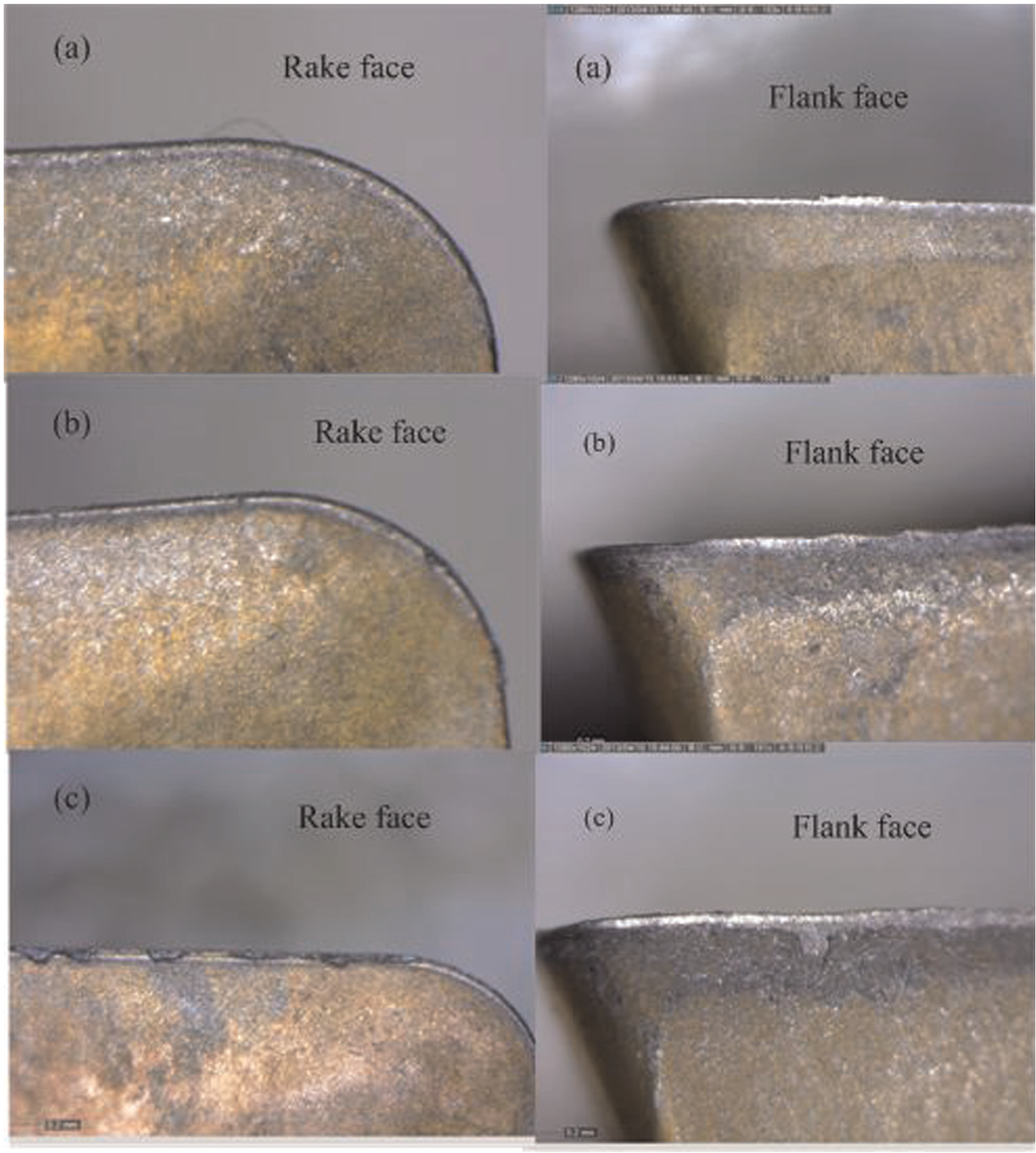
Failure history of coated carbide insert (ae = 1 mm, ap = 5 mm, fz = 0.06 mm/z and v = 300 m/min): (a) after 500 mm, (b) after 1500 mm and (c) after 2000 mm (cutting length).
Tool failure
The milling operation is a classical intermitted cutting process, in which the cutting edges may experience fluctuating cutting forces and heat with the entry/exit of the cutting tooth. The low thermal conductivity of TC21 causes the high cutting temperature at the tool–chip contact zone close to the cutting edge. At high temperature and high contact stresses, the titanium chip maintains a very intimate contact with the tool on the tool rake surface through an interfacial layer. Therefore, tool wear in cutting titanium alloys is much more intense due to high temperature and high contact stresses at the tool–chip interface.
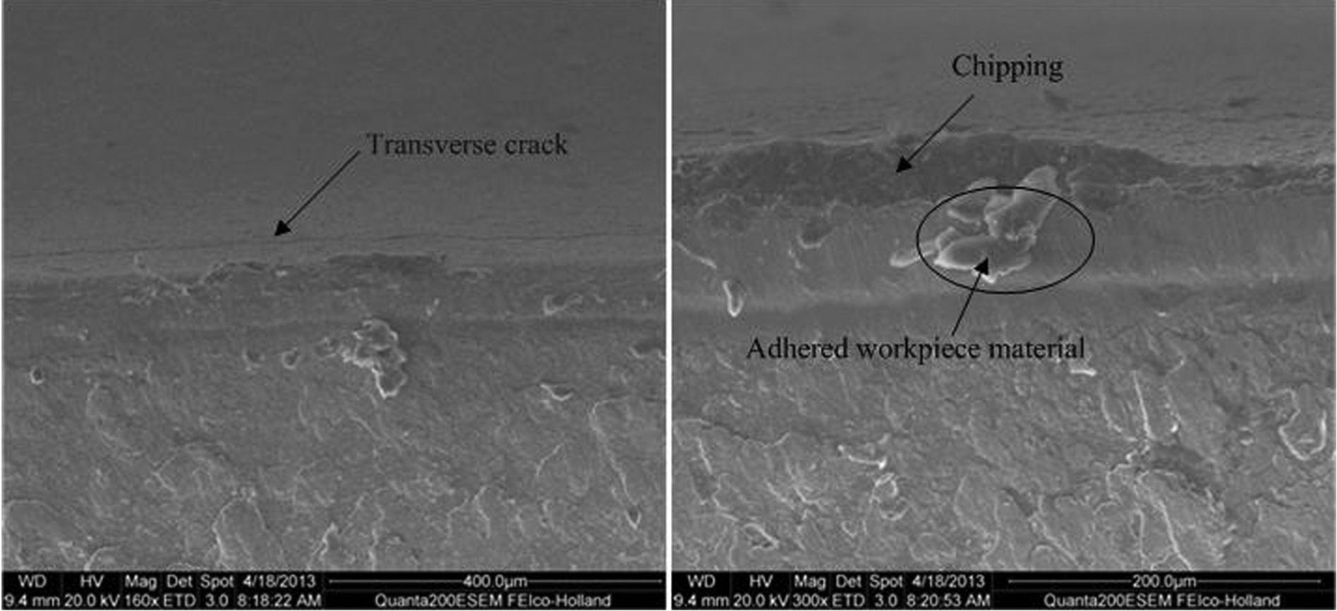
Figures 10–12 show the SEM images for the wear modes of tools in high-speed milling of TC21 alloy. The main wear modes were coating flaking, chipping, adhesion and mechanical fatigue in both the rake face and the flank face.
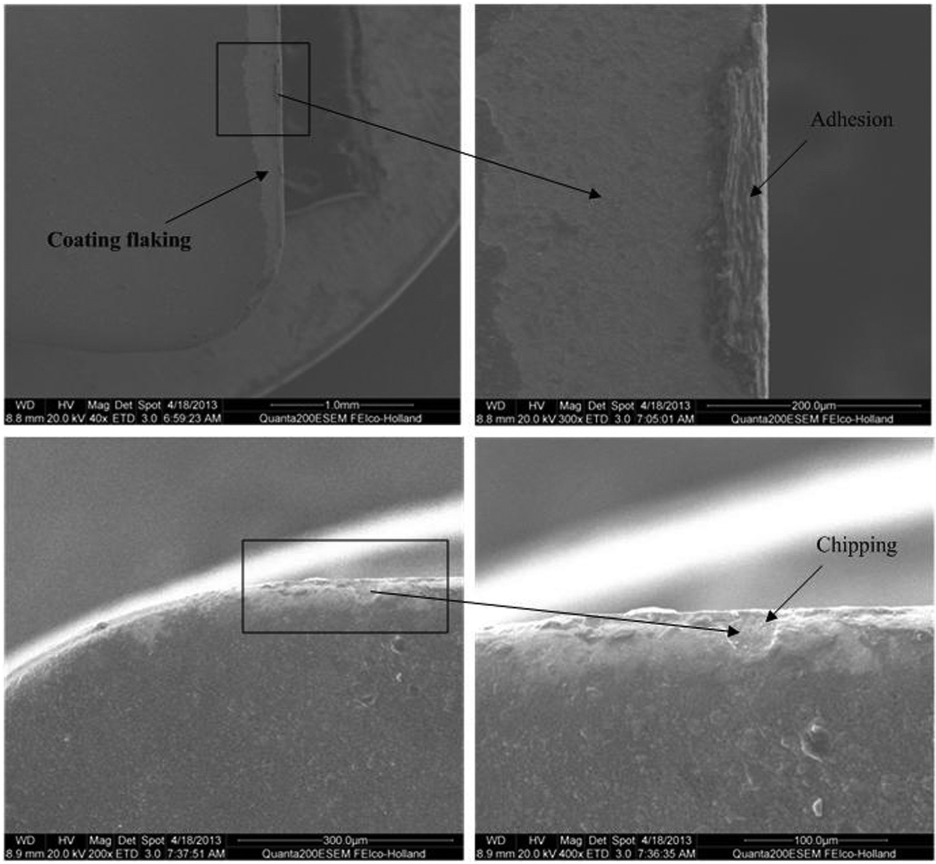
Wear modes in the rake face of tool.
Wear modes in the flank face of tool.
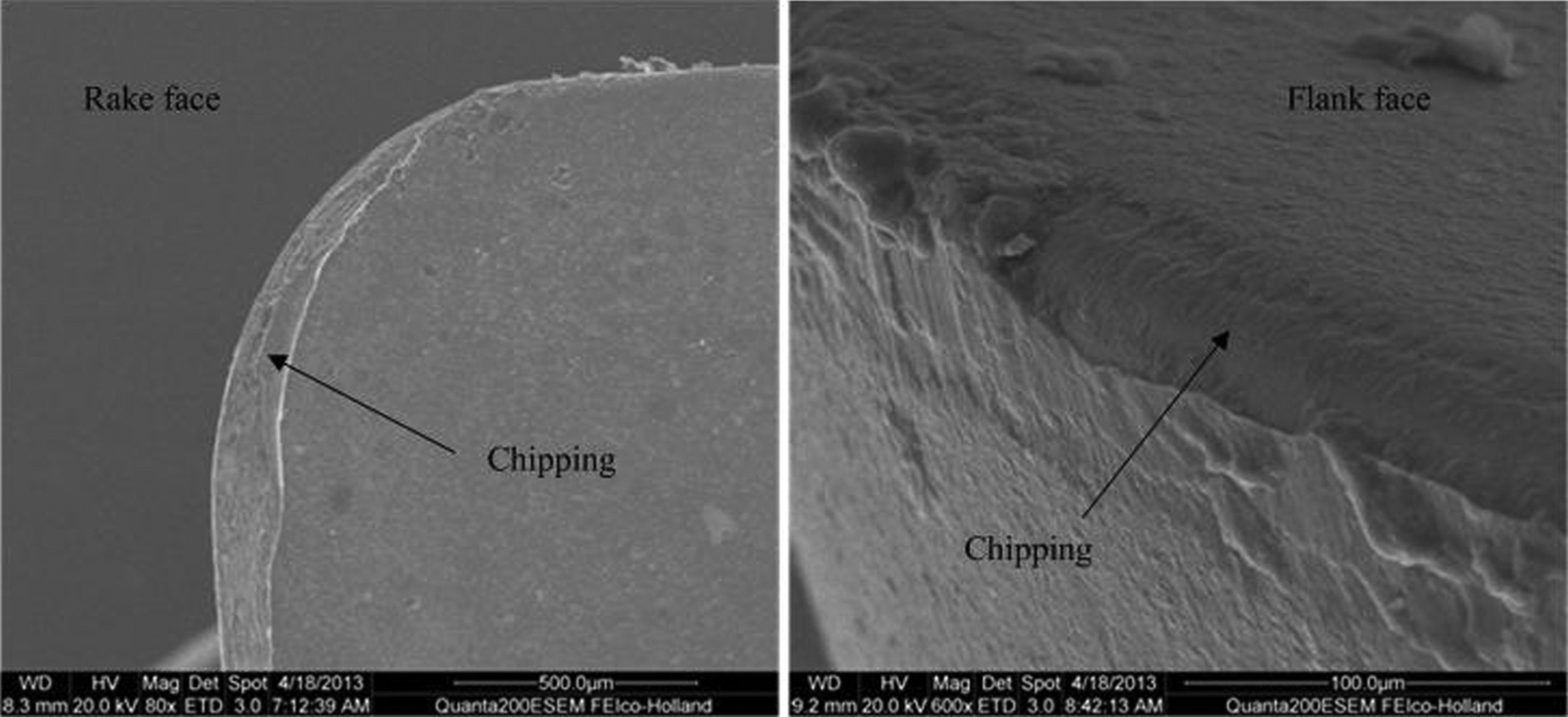
Nose depression profile in rake and flank face.
Adhesion of the workpiece materials onto the rake face of the tool was observed (see Figure 10), and it indicates that there is a strong bond at tool–chip interface. The thermal softening of workpiece materials caused by higher temperature and higher stresses in the tool–chip contact region should be the main reason that causes the adhesion of workpiece material onto the rake face. From Figures 10–12, obvious chipping can be observed on the rake face of the cutting tool when machining titanium alloy, and the main reason is the weakening of bonding between carbide and binder due to the high temperature in high-speed machining.
Figure 11 presents the flank wear, which is mainly caused by the physical abrasion and can result in the gradual wearing away of the cutting edge and a zero clearance angle on the flank face. Transverse crack parallel to the rake face was found in the SEM images under the cutting speed of 300 m/min, which is identified as typical mechanical crack as a result of cyclic mechanical loadings.
As shown in Figure 12, the crater wear almost met flank wear at the tool cutting edge and as a result, edge depression occurred. Wear along the flank and rake faces led to the concentration of stress over a certain area of the cutting edge, which was initiated by a microcrack and then propagated due to the loading and unloading effects during the intermittent milling process until significant fracture occurred in the substrate material. The greater cutting temperature generated on the cutting edge close to the nose reduced the yield strength of the tools leading to higher wear.
Conclusion
This article experimentally investigates the cutting forces and the tool wear during high-speed side-milling TC21 alloy with coated cemented carbide inserts. The following conclusions can be drawn from this article:
During high-speed milling TC21 alloy, the cutting force component in the negative x direction is more dominant of the three components and has intimate correlation with the tool wear progress. The cutting forces increase with the tool wear progresses, and the increase in cutting forces in turn deteriorates the cutting condition, accelerates the tool wear progression and shortens the tool lifetime.
The cutting forces when milling TC21 are obviously higher than that when milling TC4 under the same conditions. It means that TC21 is more difficult to cut than TC4, and the more stringent requirements on the tool for TC21 were put forward.
The major tool wear modes in high-speed milling TC21 alloy with coated carbide are adhesion and chipping at the crater wear along with adhesion and abrasion at the flank wear. Moreover, there has been mechanical crack parallel to the cutting edge. When cutting at higher speed, the cutting tools were subjected to complex and synergistic interactions among several kinds of failure mechanisms, which need to be investigated in the future.
Footnotes
Declaration of conflicting interests
The authors declare that there is no conflict of interest.
Funding
This study was financially supported by the National Basic Research Program of China (grant no. 2009CB724402).