
Abstract
This article presents the development of a three-dimensional finite element model to simulate the high-speed end milling of Ti-6Al-4V titanium alloy based on the commercial finite element package Abaqus/Explicit. The Johnson–Cook material constitutive model was employed to model the flow stress behavior of the workpiece. Zorev’s friction model was used to determine the frictional behavior of the tool–chip interface, and Johnson–Cook shear failure criterion was used to realize chip separation. Based on the three-dimensional finite element model, cutting forces in three directions were predicted under different cutting conditions, and chip evolution and morphologies of different cutting parameters were also analyzed. Corresponding high-speed end milling tests were conducted, and cutting forces were measured using a piezoelectric dynamometer in order to validate the finite element model. The simulation results demonstrate an acceptable agreement with experimental results in both the chip morphologies and cutting forces in the range of cutting speed and feed rates considered.
Introduction
Ti-6Al-4V alloy is known as difficult-to-machine materials because of its low thermal conductivity, high chemical reactivity with cutting tool materials, and low modulus of elasticity. 1 Though experimental-based testing has continued to be the primary method for machinability evaluation and cutting parameter optimization, the direct experimental approach to study machining processes is very expensive and time-consuming, especially when a wide range of parameters is included. In addition, there are still many significant physical quantities such as stress contours, strain rates, and temperature field in the tool and workpiece that are difficult to be obtained directly through experiments. The finite element method (FEM) is an effective method to predict the deformations, stresses, and strains in the workpiece, as well as the loads on the tool working under specific cutting parameters. The goal of finite element analysis is to get insight into the cutting phenomena and cutting mechanics. 2 In the last few decades, FEM has become a useful tool to investigate the metal cutting process, and many numerical models based on FEM have been developed for metal cutting simulations.
Tay et al. 3 first developed an initial two-dimensional (2D) finite element orthogonal cutting model, and temperature distributions in the chip and cutting tool were investigated based on the model. From the 1990s, wide applications of commercial software enable proper modeling of different machining processes. However, due to the complexity of actual machining process, the cutting process is often simplified as 2D finite element models based on plane strain assumption. Özel and Altan 4 developed a methodology for simulating the cutting process in high-speed flat end milling operations using commercial FEM software DEFORM-2D. Davim and Maranhão 5 studied the plastic strain and plastic strain rate in high-speed machining of steel AISI 1045 using AdvantEdge™, supplied by Third Wave Systems. Guo et al.6,7 proposed a new coupled thermal–mechanical hybrid model via the user material subroutine using Abaqus/Explicit.
Though it is easy to develop a 2D finite element model with a good approximation for the machining simulation, 2D modeling can only be used for the orthogonal cutting process, where the deformation of the chip is considered as plain strain problem. For milling operations, the plain strain assumption is not suitable because of the complex geometry of the mill, and it is difficult to simplify the milling operation using 2D finite element model. Therefore, three-dimensional (3D) finite element model is necessary in order to improve the accuracy of the model of milling operations.
Asad and Mabrouki 8 exploited a 3D finite element model for rough to finish down-cut milling operations of an aluminum alloy. Soo and colleagues9,10 developed a 3D finite element model simulating the high-speed ball nose end milling process of Inconel 718 alloy using Abaqus/Explicit. Özel and colleagues11,12 presented a 3D finite element model for hard turning with variable micro-geometry inserts using FEM software DEFORM-3D. Maurel-Pantel et al. 13 presented 3D FEM simulations of shoulder milling operations on a 304L stainless steel using the commercial software LS-DYNA. The 3D FEM involves different element formulation, different remeshing algorithm, and different boundary conditions compared with the 2D FEM simulation, so an independent approach is necessary.
The objective of this article is to develop a reliable 3D finite element model based on the actual machining process to simulate the high-speed end milling operation. Then, based on the 3D finite element model, cutting forces in three directions were predicted under different cutting conditions. In order to validate the finite element model, high-speed end milling tests were carried out, and cutting forces were measured and compared with the simulation results.
Finite element modeling of end milling
Material model
In finite element analysis, the workpiece material was modeled as elastic–plastic with isotropic hardening, and the flow stress was defined as a function of strain, strain rate, and temperature. Commonly used material constitutive models include the following: the Johnson–Cook (JC) material model; 14 the Baummann–Chiesa–Johnson (BCJ) model; 15 and the Steinberg–Cochran–Guinan (SCG) model, 16 among which the JC material model 14 is widely used to describe the workpiece material behaviors in simulation of metal cutting since the effects of strain hardening, strain rate hardening, and thermal softening on the material deformation are involved in the model. The expression of the JC material model is as follows
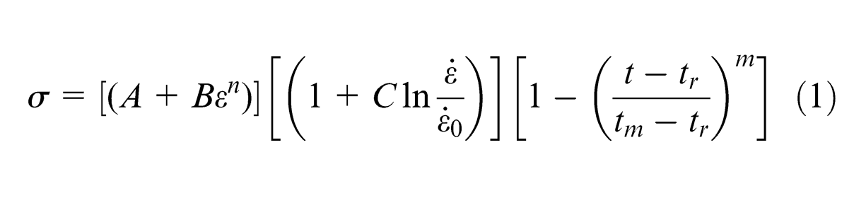
In equation (1), σ is the equivalent flow stress, ε is the equivalent plastic strain,
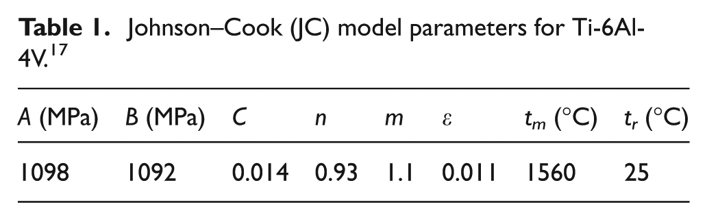
Johnson–Cook (JC) model parameters for Ti-6Al-4V. 17
Chip separation criterion
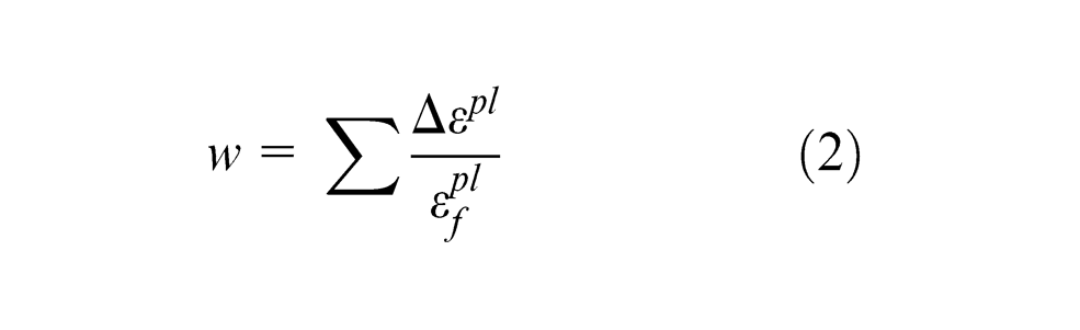
Chip separation criterion is necessary to realize the chip separation from the workpiece. Though definition of separation line between the uncut chip and workpiece along the tool path is another method used by many researchers in the earlier studies, it cannot reflect the mechanical and physical mechanisms of the chip formation, and often, the chip geometry, stress distribution, and especially the temperature distribution in the primary deformation zone are not reasonable. 18 In this study, JC shear failure criterion is used instead of separation line. In the Abaqus/Explicit software, the damage parameter based on the equivalent plastic strain follows a cumulative damage law and is given as
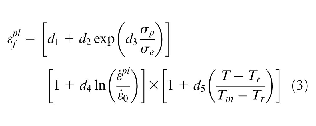
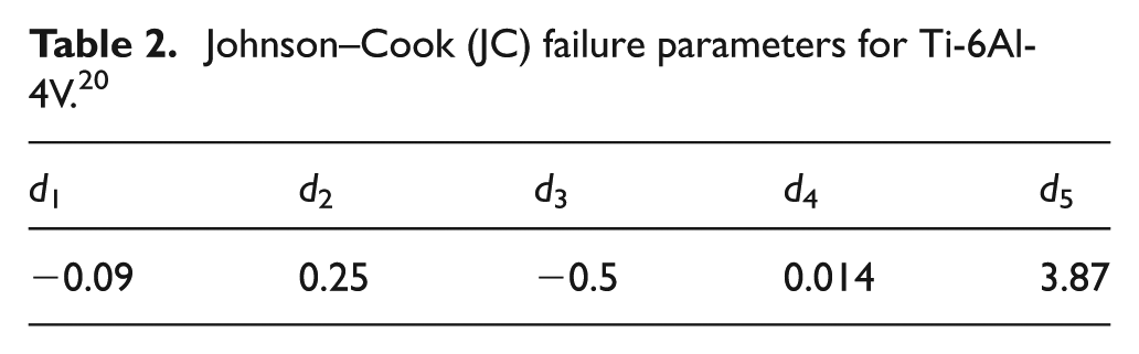
where (d1–d5) are the failure parameters measured at or below the transition temperature, listed in Table 2.
Johnson–Cook (JC) failure parameters for Ti-6Al-4V. 20
Tool–chip friction model and heat generation
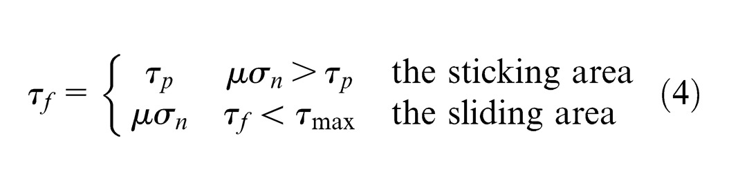
The frictional behavior of the tool–chip interface has a significant effect on frictional and normal forces as well as the heat generated by friction. Özel 21 suggested that the frictional conditions between the tool and the workpiece as well as the tool–chip interface are highly complex and very important. In fact, the construction of friction model is very difficult due to the uncertainty of friction coefficient in metal cutting simulation. 22 According to Zorev, 23 the normal stress reaches the maximum at the tool tip and gradually decreases to zero at the point where the chip separates from the rake face, as shown in Figure 1. The frictional shearing stress distribution is more complicated than the normal stress. The tool–chip contact area can be divided into sticking area and sliding area based on Zorev’s 23 analysis. The normal and shear stress distributions on the tool rake face can be expressed by equation (4)
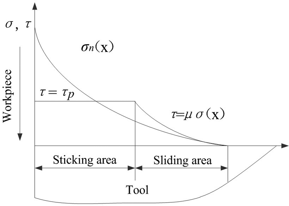
Curves representing normal and frictional stress distributions on the tool rake face according to Zorev. 23
Zorev’s friction model is widely used in metal cutting simulations. In order to determine the friction coefficient µ, friction and wear tests were carried out. Figure 2 shows the schematic diagram of the friction and wear tests. Figure 3 gives the instantaneous friction coefficient of Ti-6Al-4V ball sliding against TiAlN-coated carbide in dry condition; the load applied to the Ti-6Al-4V ball is 50 N and the sliding speed is 2 m/s, which is close to the actual machining conditions. The average friction coefficient in the stable stage is about 0.308, and it is used in the 3D finite element modeling.
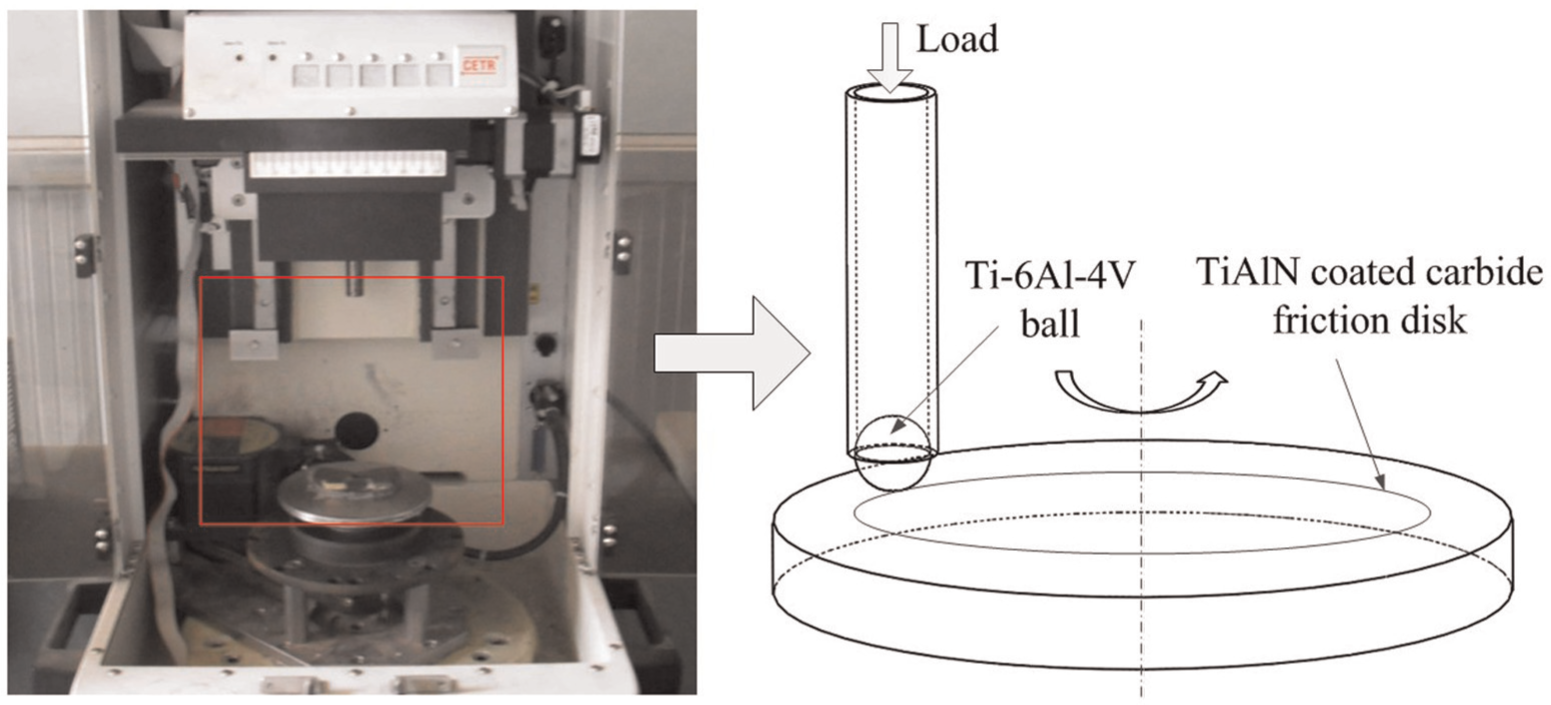
Schematic diagram of the friction and wear tests.
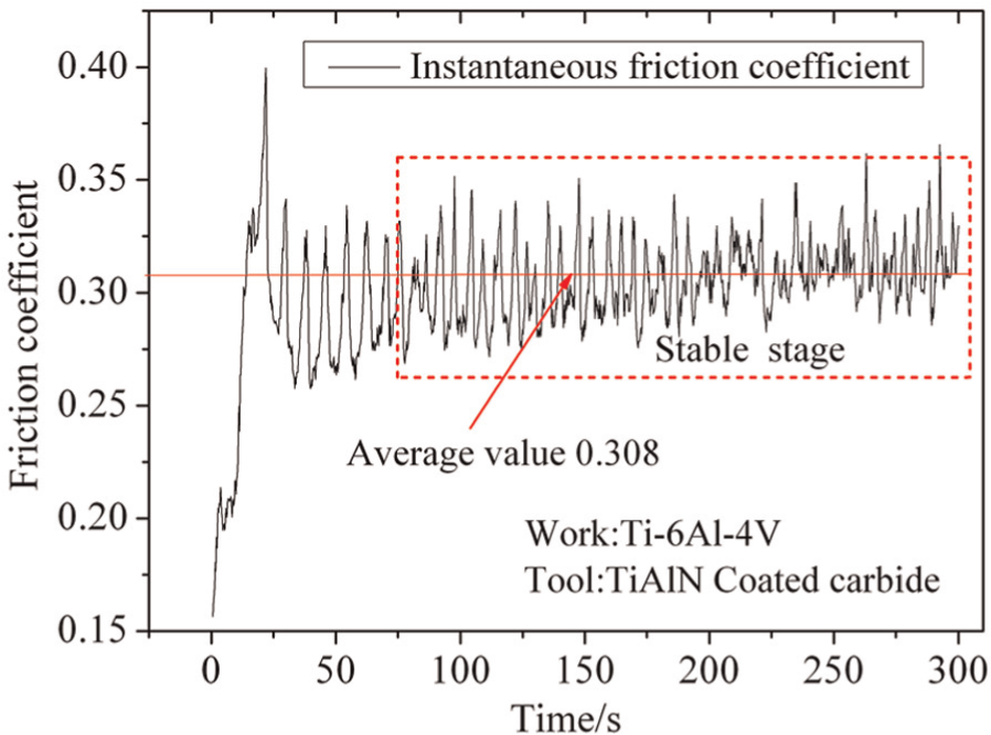
Friction coefficient of Ti-6Al-4V ball sliding against TiAlN-coated carbide in dry condition (load = 50 N, sliding speed = 2 m/s).
The heat energy in metal cutting is mainly generated by large plastic deformation in the primary deformation zone and the friction between chip and tool rake face in the second deformation zone. The energy generated by the large plastic deformation that occurs in metal cutting is considerable, and this heat source can be defined by equation (5)

where

where
Geometric modeling and meshing
The geometric model of the 3D end milling finite element analysis was created in Abaqus/Explicit, as shown in Figure 4(a). The milling operation during simulation was conducted in the down-cut milling type, and the cutting edge radius was taken into account in the geometric model to give a better accordance with the actual machining process. Figure 4(b) illustrates the initial relative position of the workpiece and the cutter. The angle θ was defined as entry angle.
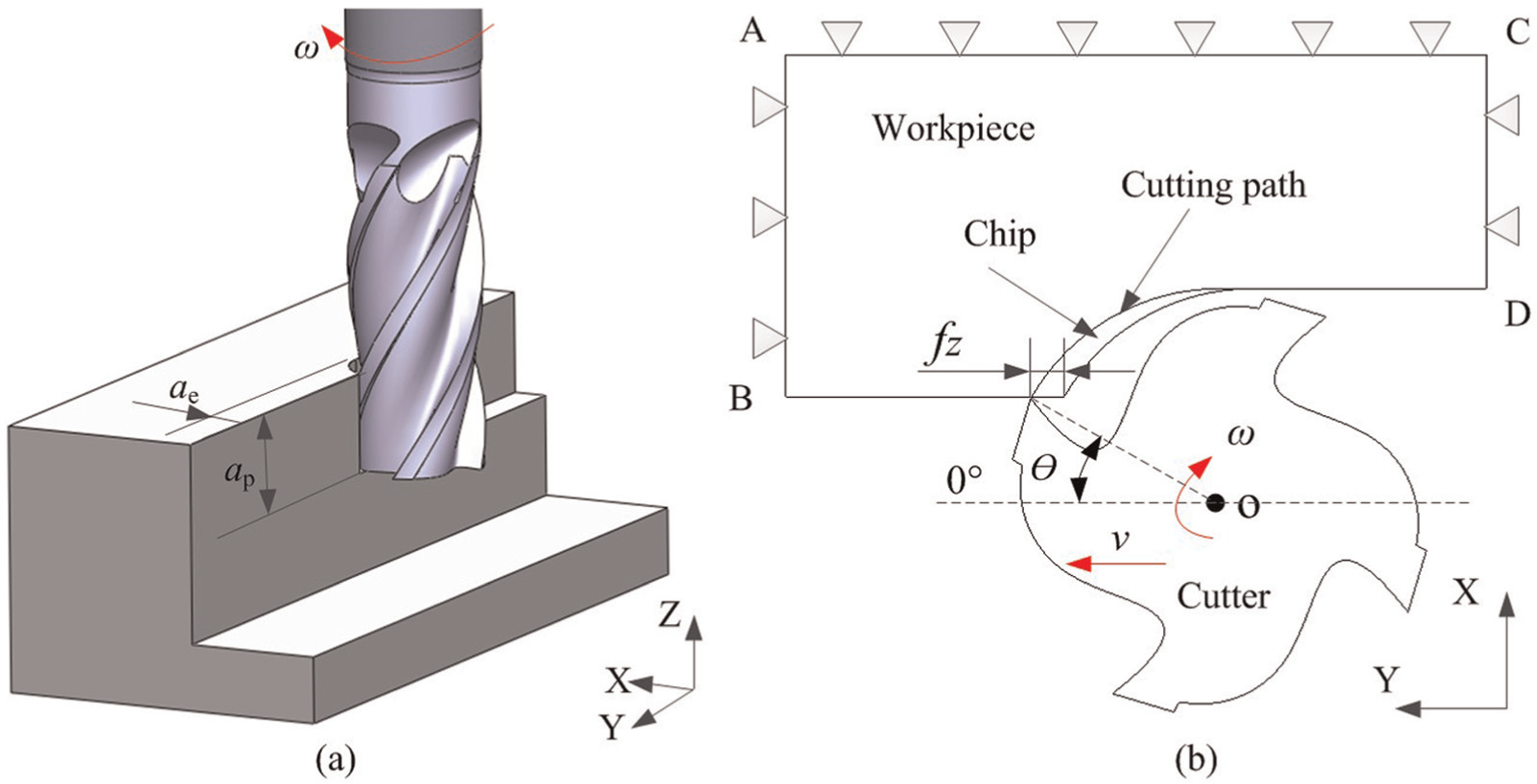
Geometric model of end milling operations: (a) geometric parameters and tool engagement and (b) cutting path.
The workpiece was defined as elastic–plastic and was meshed into 157,324 elements and 184,545 nodes. The element type of workpiece was set as a 3D solid element (C3D8RT), as shown in Figure 5(b). The C3D8RT is defined as a hexahedral eight-node thermally coupled brick, and a first-order (linear) interpolation solid element, which has one integration point, three translational degrees-of-freedom per node, and six stress components in each element output. In addition, hourglass control and distortion control techniques were employed to relieve the excessive deformation of the mesh during the chip formation. The mesh in the region where the chip was separated from the workpiece was refined, shown in Figure 5(b), so as to increase the accuracy of resolution in analysis. In contrast to the workpiece, the end mill was defined as a rigid body, in which deformation is neglected. And the element type is C3D4T (four-node thermally coupled tetrahedron, linear interpolation solid element) with a total of 16,579 elements and 18,524 nodes. A reference point was defined in the axis of the tool, and the overall motion of the mill was tied to the reference point. The feed rate and the rotational speed of the mill were applied to the reference point according to the cutting parameters used in the experiment.
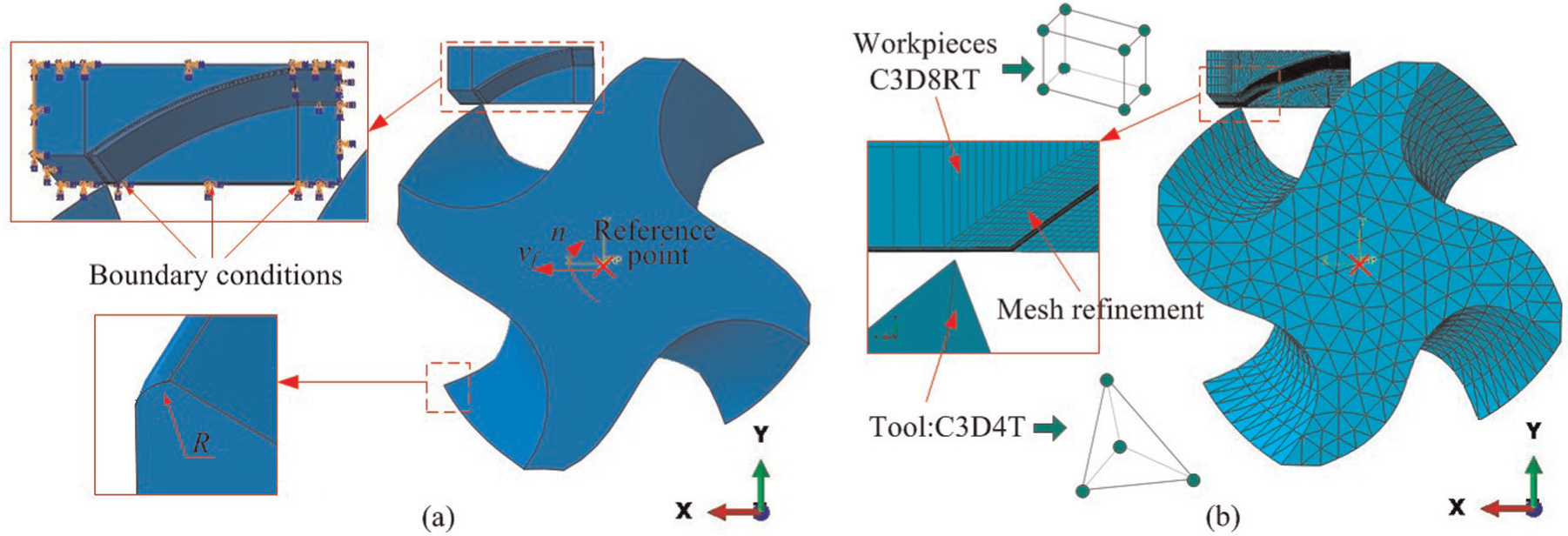
The finite element model: (a) boundary conditions and (b) meshing of the tool and workpiece.
The boundary conditions of the finite element model were shown in Figure 5(a). The movement of the workpiece in the three directions was constrained. The end mill was defined to rotate around the axis and feed progress in the Y-direction. The feed velocity was determined from the equation vf = z×fz×n, where z is the number of teeth, fz is the feed per tooth, and n is the spindle speed.
Experimental verification
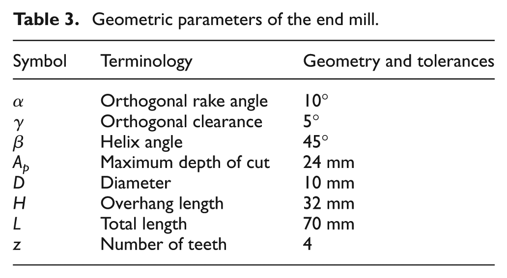
In order to validate the finite element model, high-speed end milling experiments were conducted under a wide range of cutting conditions. The experimental set-up is presented in Figure 6(a), and the tool geometry is described in Figure 6(b), while the geometric parameters are shown in Table 3. The diameter of the end mill is 10 mm, orthogonal rake angle is 10°, orthogonal clearance is 5°, helix angle of four teeth is 45°, and cutting edge radius is about 5 µm, which is the same as the geometric model of tool presented in the finite element analysis.
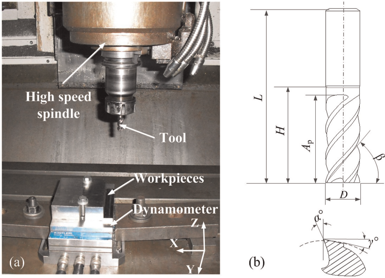
(a) Experimental set-up and (b) end mill geometry description.
Geometric parameters of the end mill.
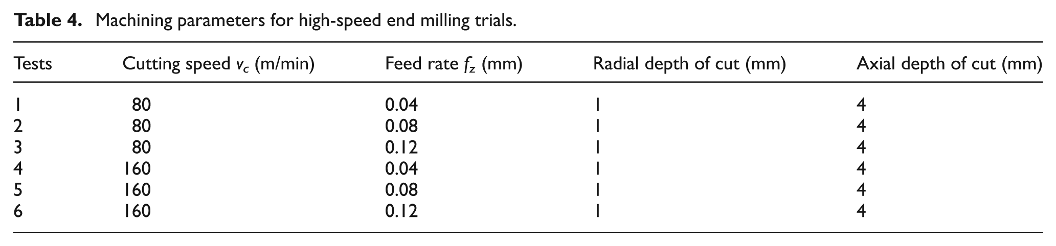
High-speed end milling operations of Ti-6Al-4V titanium alloy were performed in a vertical computer numerical control (CNC) machining center DAEWOO ACE-V500. Cutting forces were measured and recorded by a Kistler 9257B piezoelectric dynamometer mounted on the machine tool, shown in Figure 6(a). The milling tests were carried out in the dry milling and down-cut milling types at three different feed rates (fz = 0.04, 0.08, and 0.12 mm) and two different cutting speeds (vc = 80 and 160 m/min), as shown in Table 4. During the experimental trials, the cutting length of each test was 10 mm, and the wear effect of the end mill was neglected because of the short cutting time.
Machining parameters for high-speed end milling trials.
Results and discussion
In this section, the results of the simulation concerning 3D high-speed end milling operations on Ti-6Al-4V are presented and discussed. The numerical results are compared with the experimental data in terms of chip formation and chip morphologies as well as cutting forces in three directions under different cutting conditions.
Chip formation and chip morphology
Figure 7 illustrates the evolution of chip formation during the simulation under the cutting conditions of vc = 160 m/min and fz = 0.08 mm. The initial position of the end mill just before it penetrates into the workpiece is shown in Figure 4(b). With the rotational movement and feed progress of the end mill, the cutter cuts into the workpiece, as shown in Figure 7(a), and then, the chip starts to take shape and curl along the cutting direction due to the extrusion and friction effect between mill and chip, as shown in Figure 7(b)–(g). Finally, the chip is fully separated from the workpiece, as shown in Figure 7(h). It can be observed that the max Mises stress of the workpiece is located in the primary deformation zone during the process of chip formation, which is coincident with the actual machining process. In addition, it can be observed that the max Mises stress in the primary zone increases with the increase in the contact length between the mill and the chip and reaches 1640 MPa at the entry angle of 50°, as shown in Figure 7(d). The possible reason for the phenomenon is the severe plastic deformation of the chip lead to the contact stress increase in the process of chip formation.
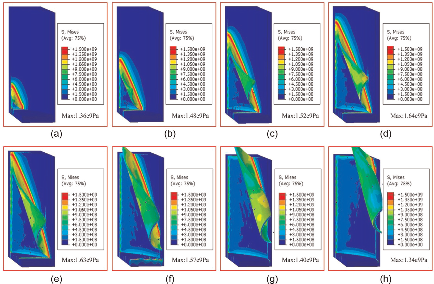
Mises stress contours and chip evolution in high-speed end milling (vc = 160 m/min, fz = 0.08 mm): (a) Θ = 20°, (b) Θ = 30°, (c) Θ = 40°, (d) Θ = 50°, (e) Θ = 60°, (f) Θ = 70°, (g) Θ = 80°, and (h) Θ = 90°.
Figure 8 shows the predicted and experimental chip morphologies under different feed per tooth when the cutting speed is 160 m/min. The Mises stress and temperature distribution of the chip are presented with the variations of the feed per tooth. It can be seen that the simulated chip morphologies have a good agreement in the geometric features with the actual chip morphologies in experiments.
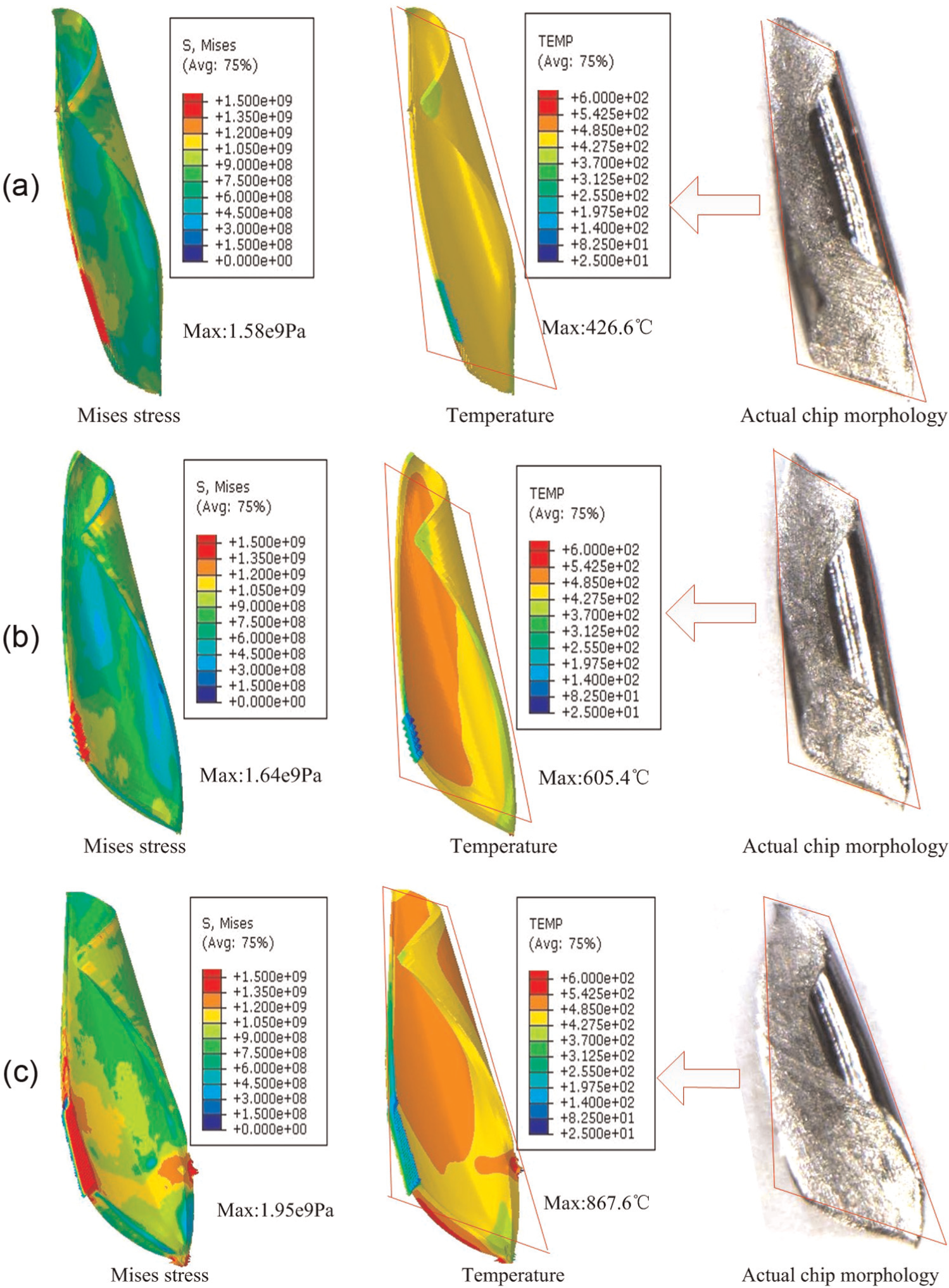
Comparison of chip morphologies between simulation and experiments under vc = 160 m/min: (a) fz = 0.04 mm, (b) fz = 0.08 mm, and (c) fz = 0.12 mm.
Figure 9 presents the effects of milling parameters on Mises stress and temperature of the chip during the simulation process. As the values of Mises stress and temperature on the chip are not constant at different stages but vary with chip formation, the maximum values during the chip formation were selected to compare. It can be seen that the maximum chip temperature increases with both feed per tooth and cutting speed and reaches 867.6 °C under the cutting conditions of vc = 160 m/min and fz = 0.12 mm. However, the effects of milling parameters on the Mises stress of the chip are not obvious, as shown in Figure 9(a).
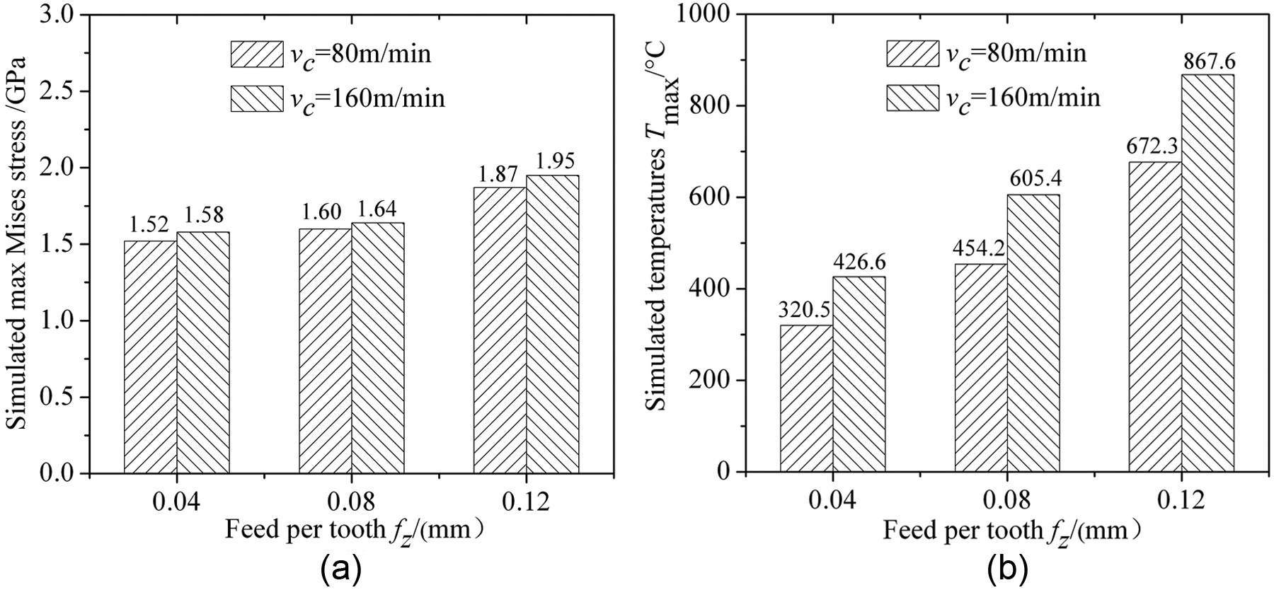
Simulated chip characteristics: (a) Mises stress and (b) temperature.
Cutting forces
Figure 10 shows the evolution of instantaneous cutting forces in three directions under the cutting conditions of vc = 80 m/min and fz = 0.08 mm. It can be seen that the cutting force in the X-direction increases rapidly and reaches the peak value when the tool cut into the workpiece and then decreases slowly to zero when the tool cut out with a little fluctuation caused by tool vibration. The milling tests were conducted in the down-cut milling type, which results in a rapid increase in load on the tool due to the rapid change in chip thickness. Meanwhile, the axial depth of cut in milling tests is small enough; only one tooth is in the cutting position at a time. The cutting time of each tooth is defined as Δt, as shown in Figure 10. The cutting force in the Z-direction is more perturbed than the cutting forces Fx and Fy. One reason is that the cutting force Fz is much smaller and more sensitive than the forces in other directions, and the vibrations of machine tool in the milling process have more influence on the cutting force Fz. The intervals between two peak values is determined by the cutting speed vc; it can be expressed by the equation T = πd/zvc, where D is the diameter of the end mill, z is the number of teeth, and vc is the cutting speed.
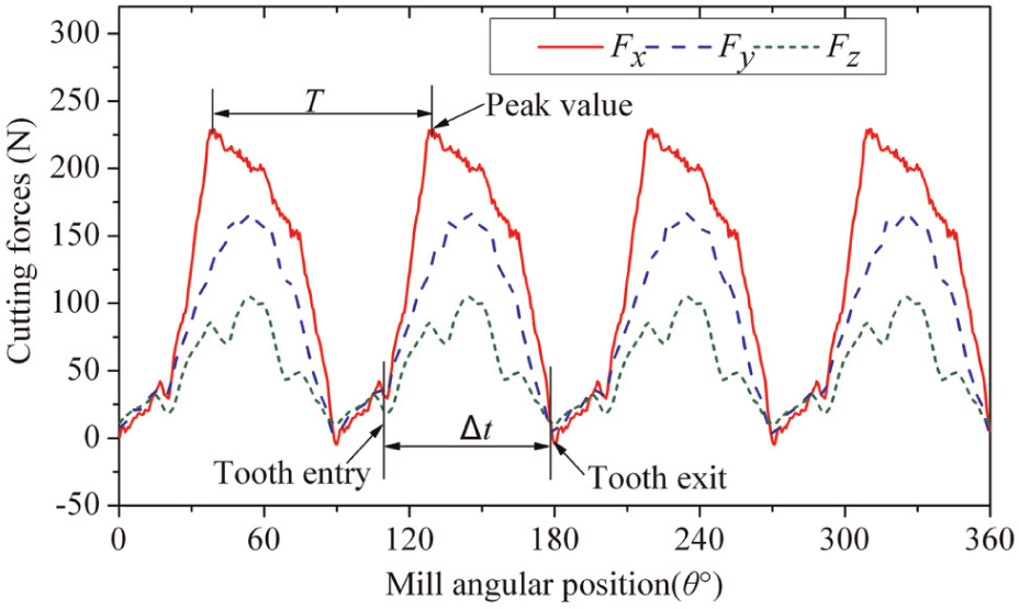
Instantaneous cutting forces in experiments (vc = 80 m/min and fz = 0.08 mm).
To validate the 3D finite element model, the simulated instantaneous cutting forces were compared with the experimentally measured cutting forces in three directions, as shown in Figure 11. A good agreement can be observed. The max simulated cutting force Fx was predicted to be 210 N, and the max simulated cutting force Fy was 151 N, while the corresponding experimentally measured values were found to be 228 and 165 N, respectively. The max percentage error is 8% approximately. For the cutting force Fz, the predicted and experimental values are 87 and 105 N, respectively, giving a max error of 17%. The errors between the simulation and experimental results are acceptable in consideration of the effects of machine tool vibration and the simulation accuracy.
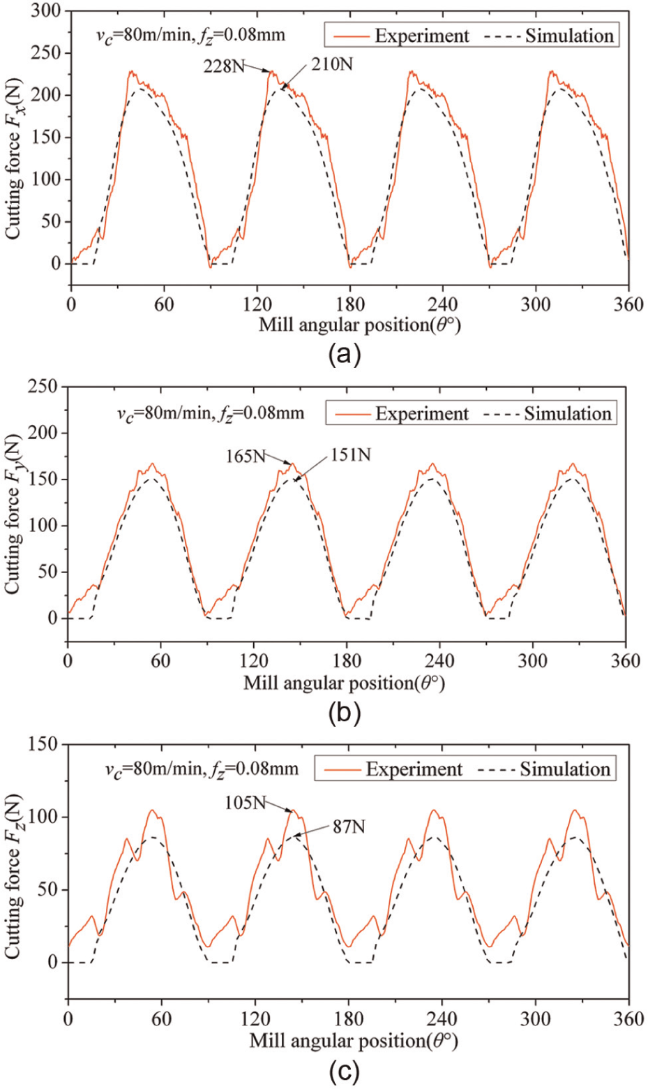
Comparison of instantaneous forces in three directions (vc = 80 m/min and fz = 0.08 mm): (a) Fx, (b) Fy, and (c) Fz.
Figure 12 shows the comparison of the simulated and experimental cutting forces in three directions under different milling conditions. The cutting forces were obtained by averaging the peak values during the cutting process in order to make the comparisons reliable. Especially, cutting forces in the X- and Y-directions are in close agreements with 6%–8% prediction error, and the predicted cutting force Fz shows 12%–15% error compared with experimental values. In addition, it can also be observed that the experimental and simulated cutting forces in cutting speed 160 m/min are higher compared with corresponding values in cutting speed 80 m/min. The feed rate also has great effect on the cutting forces. Increase in the volume of metal removal in the same period leads to the increase in the cutting forces in three directions.
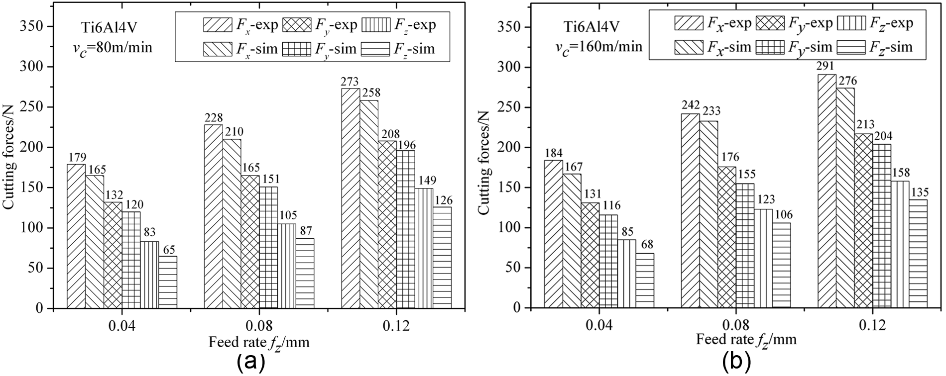
Comparison of measured and simulated cutting forces in three directions: (a) vc = 80 m/min and (b) vc = 160 m/min.
Conclusion
A thermo-mechanically coupled 3D finite element model has been developed to simulate high-speed end milling of Ti-6Al-4V titanium alloy based on the commercial FE package Abaqus/Explicit. JC material constitutive model and chip separation criterion were employed to model the behavior of workpiece and chip formation; friction and wear tests were carried out to determine the friction coefficient between tool and workpiece. In order to validate the finite element model, high-speed end milling experiments were conducted under different cutting conditions.
Evolution of chip formation was demonstrated, and the predicted Mises stress distribution of the chip during the chip formation is presented. The max Mises stress was found to be located in the primary deformation zone with a maximum of approximately 1640 MPa. Predicted and experimental chip morphologies under different feed per tooth were compared; a good agreement can be observed.
The simulated cutting forces were compared with the experimentally measured cutting forces in three directions under different cutting conditions. The predicted cutting forces show good correlation with the experimentally measured data with 6%–8% prediction error in the X- and Y-directions and 12%–15% prediction error in the Z-direction.
Footnotes
Declaration of conflicting interests
The authors declare that there is no conflict of interest.
Funding
This work is supported by the National Basic Research Program of China (No. 2009CB724402) and the National Natural Science Foundation of China (51175310).