
Abstract
Diamond-coated drawing dies are considered as the next generation of drawing dies for their unique characteristics, such as high hardness, wear resistance, low friction and thermal conductivity in the cold drawing process. In order to utilize the superior characteristics of diamond coatings toward improving the drawing performance, modified typed drawing die is developed to minimize the diameter shrinkage. Finite element model simulation is used to simulate the low carbon steel tube sinking drawing process, using a two-dimensional axi-symmetric elastic–plastic element model. The parameters of tube drawing die, such as the main reduction zone α1, the semi-angle of the secondary reduction zone α2 and the length of the secondary reduction zone L, are considered. Based on the simulation results, the cause of diameter shrinkage is studied. The influence of parameters of tube drawing dies on the diameter shrinkage is investigated using the response surface methodology. The gained equation reveals that L is the most significant parameter.
Introduction
The cold drawing process essentially consists of pulling a continuous tube through an appropriately shaped die by a draw force applied to the leading end of the tube. One of the advantages of this process is the excellent quality of the final surface finish of the product obtained. The added strength of cold drawing, the achievement of precise dimensions and the refinement of the grain structure are other benefits of this process. In addition, tube drawing generally implies a low cost as compared with the other processes devoted to tube forming. 1 In order to ensure the dimensional precision, smoothness of the final tube, high hardness and fine surface finish are required for the inner holes of tube drawing dies. The cemented carbide (WC-Co) drawing dies are widely used in most cases from a point of view of price. However, these conventional drawing dies can wear easily, and the inner diameter of the drawing die becomes larger in a short time. Hence, the outer diameter of the drawn tube becomes larger and the drawing die needs to be replaced. This leads to a waste of material and low efficiency. Thus, the cemented carbide drawing dies cannot satisfy the demands of high efficiency and high speed production. Diamond-coated drawing dies, as a new technology, have gained more attention in the industry. In recent years, a number of works on diamond coating dies were studied. Due to its unique characteristics, such as high hardness, low friction and wear resistance, the working lifetime of tube drawing dies can be notably prolonged. The diamond coating can protect the substrate from suffering wear, and the inner diameter of drawing dies can remain uncharged during whole working life. 2 Hence, the outer diameter of the production, which is drawn by diamond-coated drawing die, has good tolerance stability. For these advantages, the diamond-coated drawing die is considered as an ideal substitute in cold drawing business. The fabrication of diamond-coated dies using the hot filament chemical vapor deposition (CVD) method was studied by Zhang et al. 3 The surface morphology and thickness of the diamond coating at different positions of the die hole surface were analyzed by scanning electron microscopy (SEM) and Raman spectroscopy. Sun et al. 4 deposited composite diamond films on the inner hole surface of Co-cemented carbide drawing dies. Sarangi et al. 5 investigated the influences of pretreatment methods and chamber pressure on morphology, quality and adhesion of CVD diamond coating. The tribological and wear behavior was studied by Schade et al.6,7 Diamond coatings with a smooth surface and good adhesion were deposited on the inner hole surface of the cemented carbide drawing die. Therefore, the use of diamond-coated drawing die becomes popular.
One of the most important issues for a diamond-coated drawing die design is diameter shrinkage during tube drawing. 8 Diameter shrinkage is the difference between the diameter of the inner hole of drawing dies and the final tube. This defect is generally observed during hollow tube sinking, not in plug drawing. It is unacceptable if the diameter shrinkage is too large. The diameter shrinkage is caused by metal flowing. When the tube comes from the reduction zone to the bearing zone, it does not contact with the bearing zone surface. In general, the outside diameter of the tube becomes smaller than the inner diameter of die inner hole. The cemented carbide drawing die can be amended to eliminate this defect. However, it is impossible to amend the drawing die after the diamond coating is deposited. So, it is highly recommended to design the drawing die appropriately before the deposition. Conical die is used to reduce the tube diameter traditionally. In this study, the reduction zone is modified to a combination of two conical surfaces, in order to minimize the diameter shrinkage. A number of impressive works on cold drawing were studied. Several analytical methods, such as homogeneous deformation method, slab method, upper-bound method and finite element model (FEM) method, have been employed by Luis et al. 9 in order to obtain the forces, energies, stressed and strain that are involved in the wire drawing process. Ruminski et al. 10 investigated the influence of the shape of die working parts on the distribution of strain in the deformed material and on the distribution of mechanical properties in the final product. The drawings of shape-memory-alloy fine tubes11,12 and polymer tubes 13 have been studied using a FEM method. Kuboki et al. 14 presented a paper on the numerical simulation and laboratory experiment used for investigating the distribution of the residual stress on the drawn tube with sinking drawing and plug drawing. Chen and Huang 15 investigated the plastic deformation behavior of brass alloy wire as it was drawn through a conical die. The optimization of the tube drawing process has been done through a FEM with the objective of reducing the maximum stress level. 16 The cylindrical velocity field was established, and a new integration method of strain rate vector inner-product was applied to obtain an upper-bound solution for tube sinking drawing process. 17 Simulation and experimental validation of tube sinking drawing processes was presented by Celentano et al. 1 However, the study on diameter shrinkage has less been investigated.
In this study, we establish the axi-symmetric elastic–plastic model to simulate the tube drawing process. The drawing material is low carbon steel. The selected parameters affecting diameter shrinkage as the response are the main reduction zone α1, the semi-angle of the secondary reduction zone α2 and the length of the secondary reduction zone L. An experimentally validated FEM is used for carrying out parametric analysis. The utilized layout for simulation runs is based on Box–Behnken design.
Diamond-coated tube drawing dies
The diamond-coated tube drawing dies are fabricated using hot filament CVD method. 3 The WC-Co (Co 6 wt.%) drawing dies are used as substrates. The sketches of the conventional die and the modified type die are presented in Figure 1. In general, the die contour consists of three important zones: (1) the inlet zone, (2) the reduction zone and (3) the bearing zone. 2 With the conventional die, the low carbon tube can be deformed rapidly. The modified die can smoothen the deformation process and minimize the diameter shrinkage. The main parameter for the conventional die is the semi-angle α, and for the modified die, it is the semi-angle of the main reduction zone α1, the semi-angle of the secondary reduction zone α2 and the length of the secondary reduction zone L.
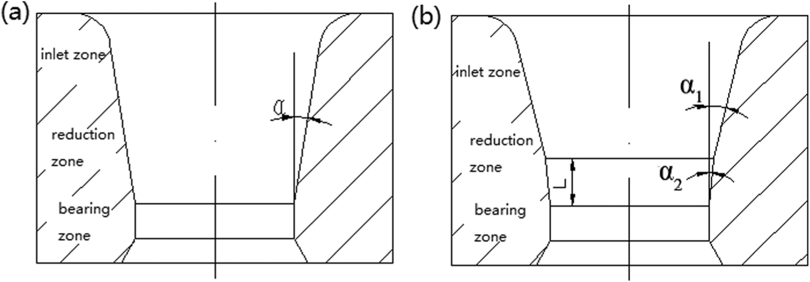
The sketch of drawing dies: (a) conventional die and (b) modified type die.
Methodology
In this article, a low carbon tube drawing process is simulated using commercial FE software. The FE model is introduced to perform simulation runs for each dictated set of input parameters of the response surface matrix’s (RSM) Box–Behnken matrix. The influences of selected input parameters of the tube drawing die are then analyzed using analysis of variance (ANOVA). The optimum parameters are predicted by using the developed mathematical model of outer diameter of final tube as the response.
Experimental details
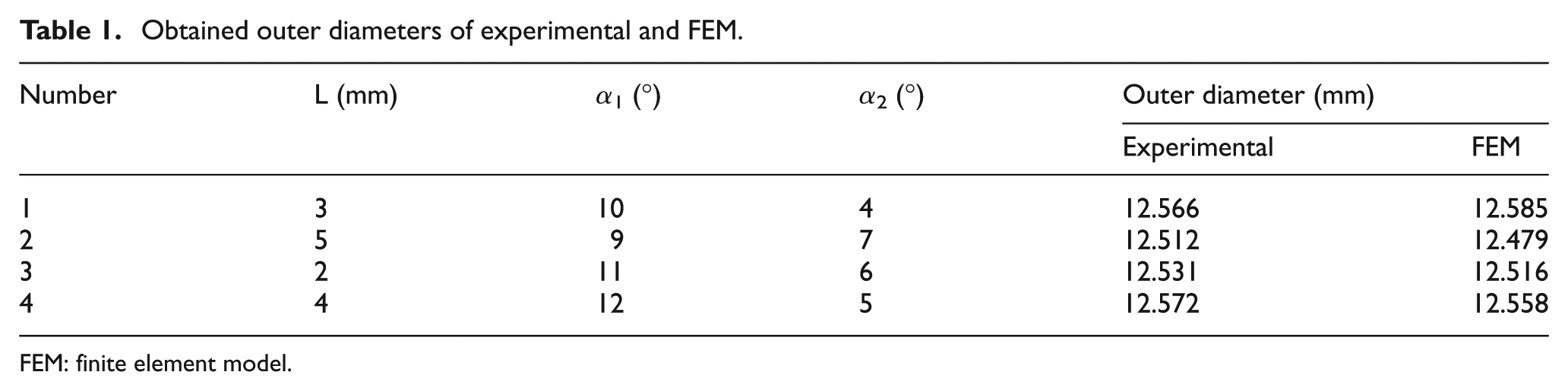
As shown in Figure 2, a drawing laboratory machine is used in this work to evidence the ability of the simulation procedure to model the outer diameter of final tube. In this study, low carbon steel tubes with an initial outer diameter of 14.00 mm and a thickness of 2.00 mm are drawn using four drawing dies, which has a 12.60 mm inner diameter. The drawing speed is 500 mm/min. Four sample tubes are used in the test, which have a length of about 800 mm. Oil lubrication is employed. Table 1 shows the parameters of drawing dies used for this study. The outer diameter values of the final tubes are measured by using diameter micrometer and are summarized in Table 1. The corresponding computed values shown in Table 1 are obtained from the FEM simulation. The results obtained in the FEM simulation are very similar to the experimental tests. This implied the validity of the model.
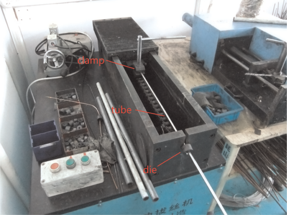
Tube drawing in a drawing laboratory machine.
Obtained outer diameters of experimental and FEM.
FEM: finite element model.
FEM simulation
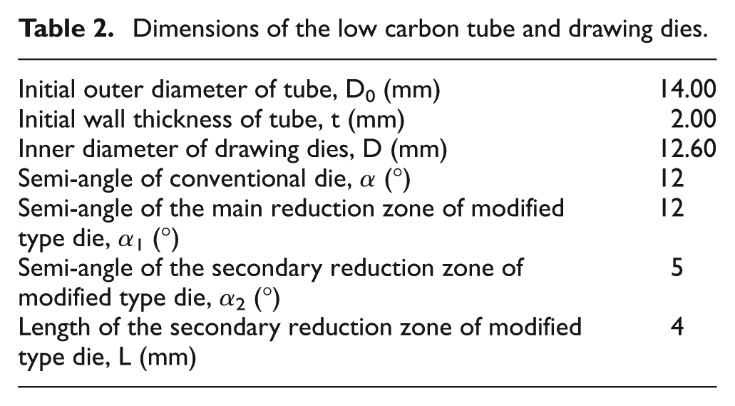
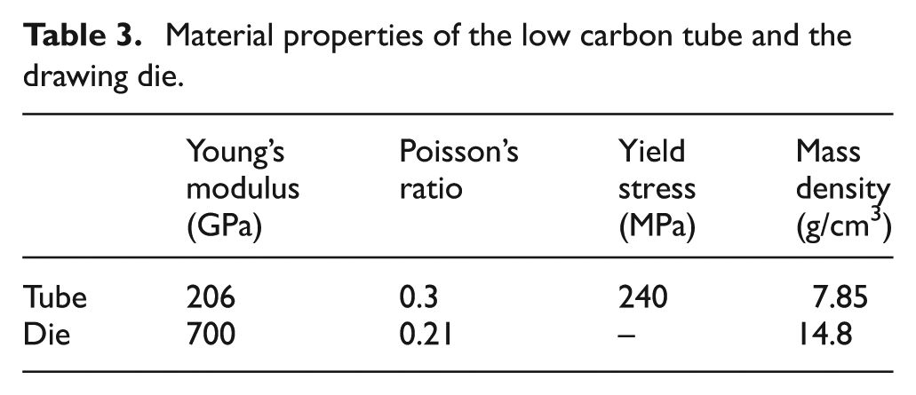
In this article, FEM simulation is used to understand the deformation behaviors of the low carbon steel tube during the tube drawing process. In the simulation process, the finite element software ANSYS Workbench V12.0 is employed in this article. Elastic–plastic analysis is carried out using a static method. A Von Mises’ yield criterion was adopted. The dimensions of low carbon tube and drawing dies are shown in Table 2. In order to reduce the computational cost, a two-dimensional (2D) axi-symmetric element model as shown in Figure 3 is introduced. The element type is eight-node quadrilateral elements. This model consists of a low carbon steel tube and a drawing die. Table 3 shows the material properties used in the simulation. Following assumptions are adopted during the simulation:
The material is isotropic and uniform. An elastic–plastic material is used to describe the deformation behavior of the low carbon steel tube. The die is characterized as a linear-elastic material.
Coulomb friction is applied to represent the friction behavior. Friction coefficient between the tube and the drawing die is set as 0.05 because of oil lubrication and good friction properties of diamond coatings.
The tube surface temperatures during drawing have been investigated by researchers experimentally. The values are no higher than 101 °C. 18 Thus, the thermal effect between the tube and the die during drawing is ignored.
The effect of gravity and inertial force is ignored.
Dimensions of the low carbon tube and drawing dies.
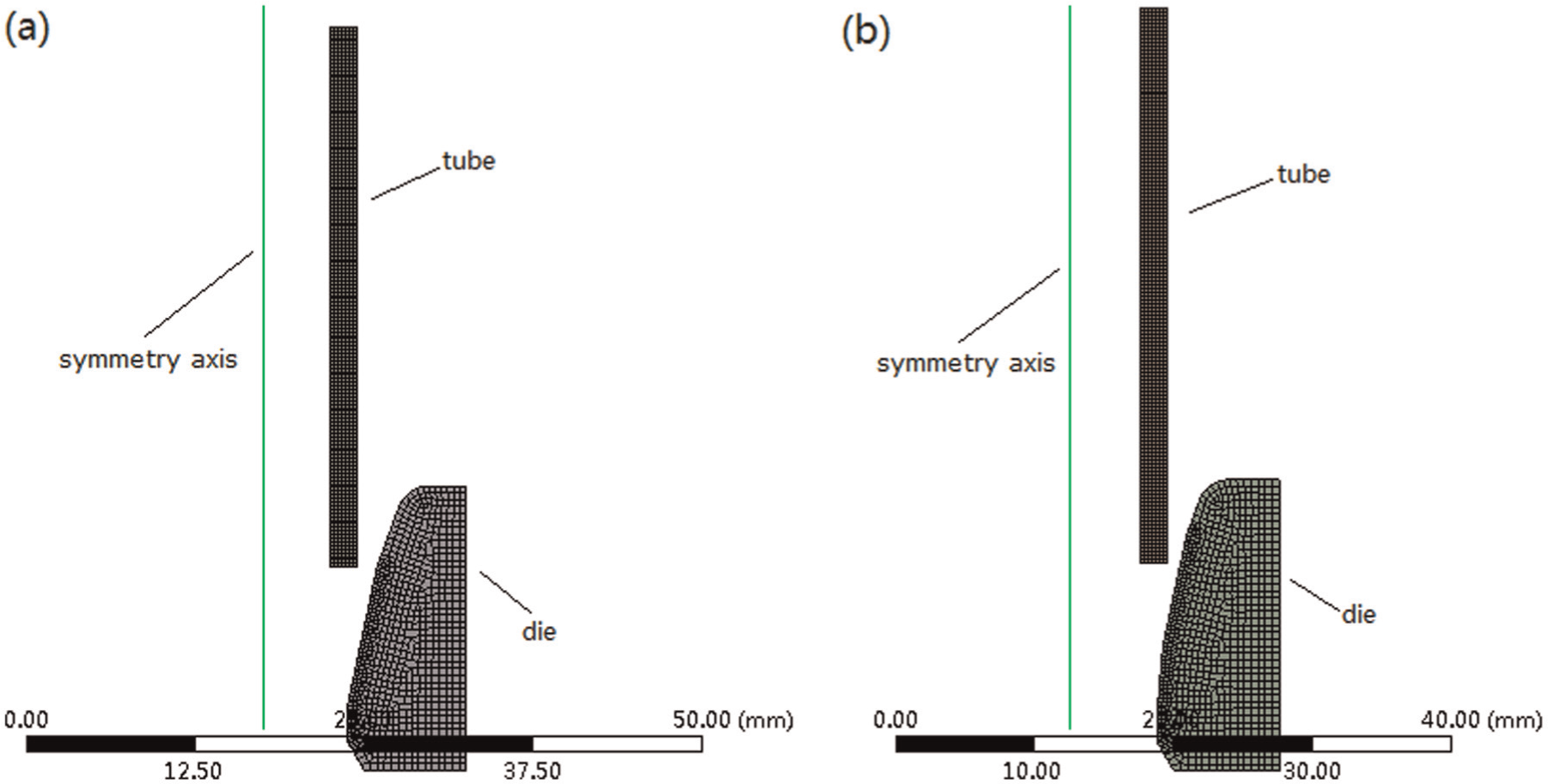
FE model of the low carbon steel tube in hollow sinking: (a) conventional die and (b) modified type die.
Material properties of the low carbon tube and the drawing die.
Design of experiments
With the aim of studying the influence of the parameters of tube drawing die on the diameter shrinkage, a numerical simulation through the design of experiments (DOE) method is carried out based on the FEM simulation previously described. Response surface methodology, as a DOE tool, is applied to obtain an approximation to a response function in terms of predictor variables. The main idea of RSM is to use a sequence of designed experiments to obtain an optimal response. 19 RSM provides an approximate response relationship between independent parameters and responses, based on several analyses of DOE results. Optimal conditions are first determined with the RSM. We create a response surface between the design parameters and objective functions considering constraint condition limits. With the created response surface, an optimal solution is obtained. 20
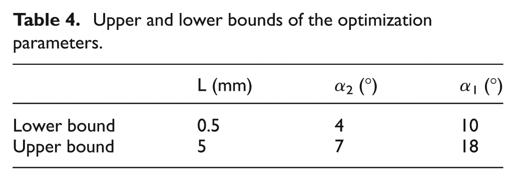
In this article, the Box–Behnken matrix dictates the experimental layout in 17 sets of runs for evaluation of three numerical factors and quantifying the mathematical model of diameter shrinkage attained by cold drawing of low carbon steel tube. The prime object of this article is to optimize the die geometry. So, the die geometry parameters are set as design parameters. The lower bound and upper-bound values of parameters considered in the RSM are shown in Table 4. The results of the simulation of the tube drawing process were measured according to the Box–Behnken design matrix and are listed in Table 5.
Upper and lower bounds of the optimization parameters.
Experimental layout for the Box–Behnken matrix.
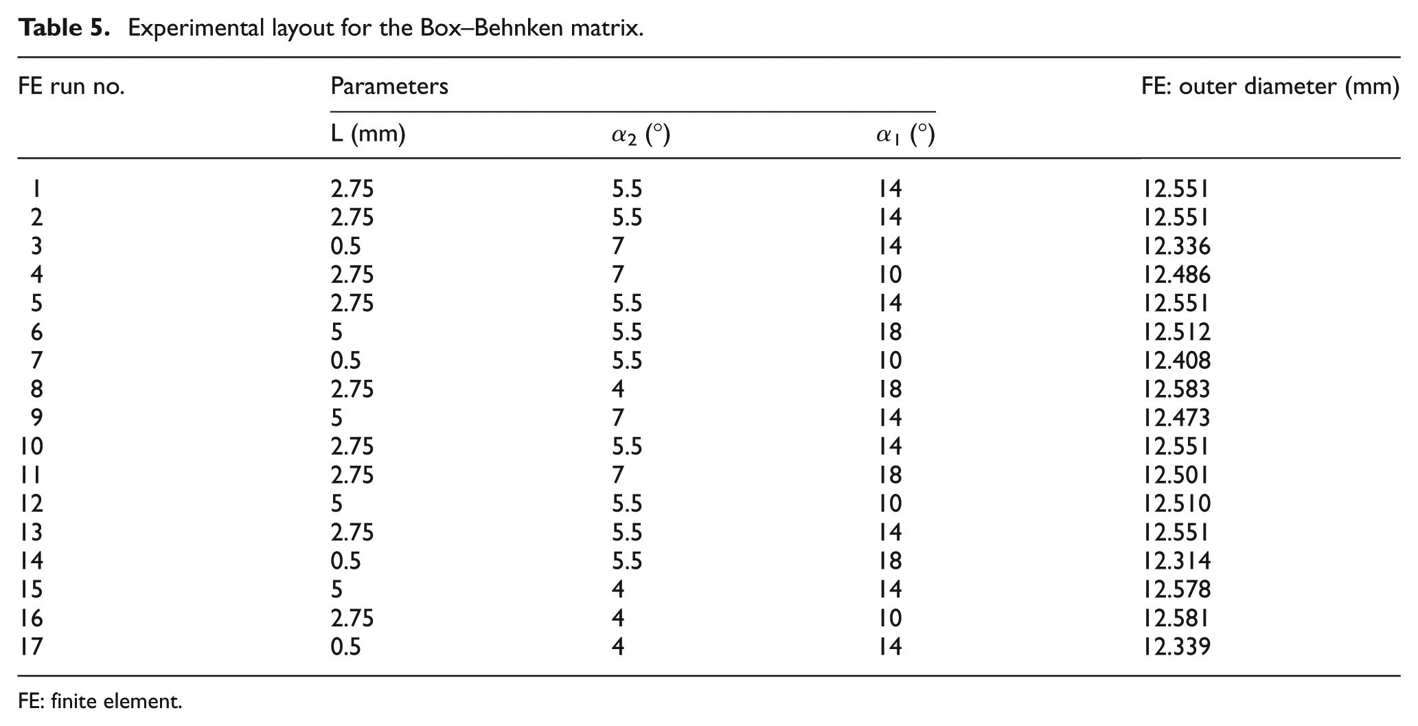
FE: finite element.
Results and discussion
Simulation results
One of the most important issues for a diamond-coated drawing die design is diameter shrinkage during tube drawing. This defect is unacceptable if the diameter shrinkage is too large. The metal flowing is the major cause of the diameter shrinkage during the tube drawing process. Diameter shrinkage, as a dimensional imperfection, is found on the low carbon tube drawing in this experimental study. Figures 4 and 5 show the simulation results of drawing process using both conventional die and modified type die, which implies that the diameter shrinkage can be significantly reduced using a modified type die.
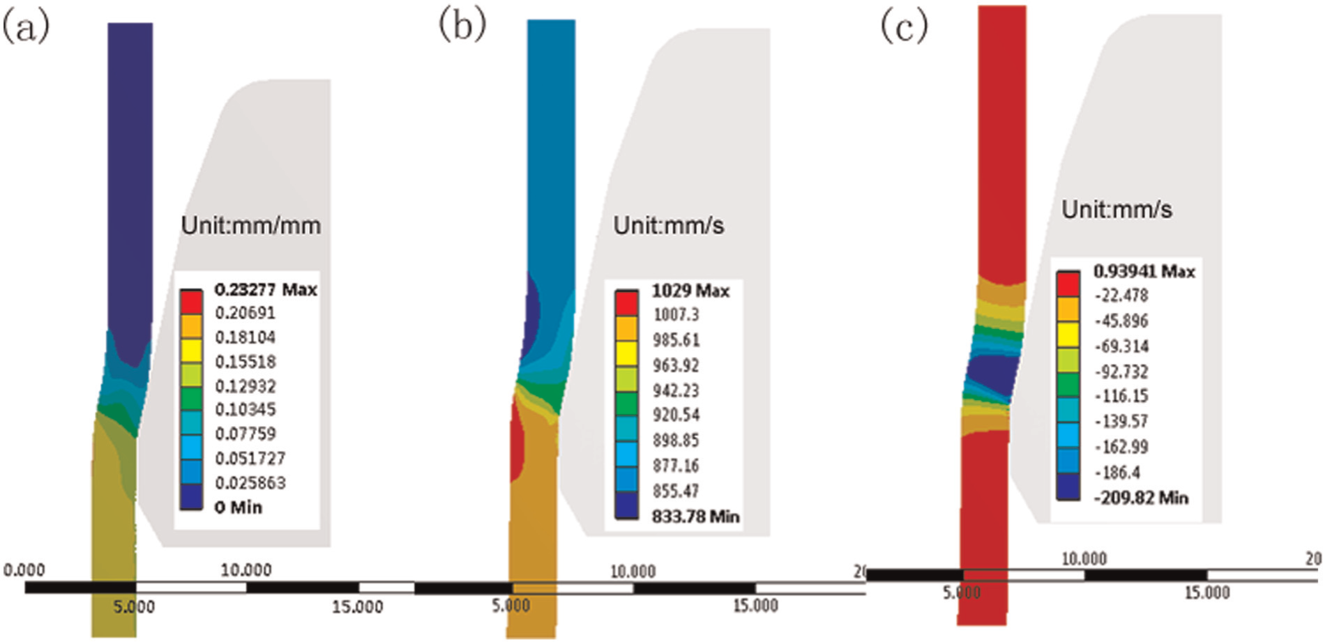
(a) The plastic strain distribution of low carbon steel tube with conventional die, (b) the flowing speed vector graph and (c) cloud graph of the flowing velocity in radial direction.
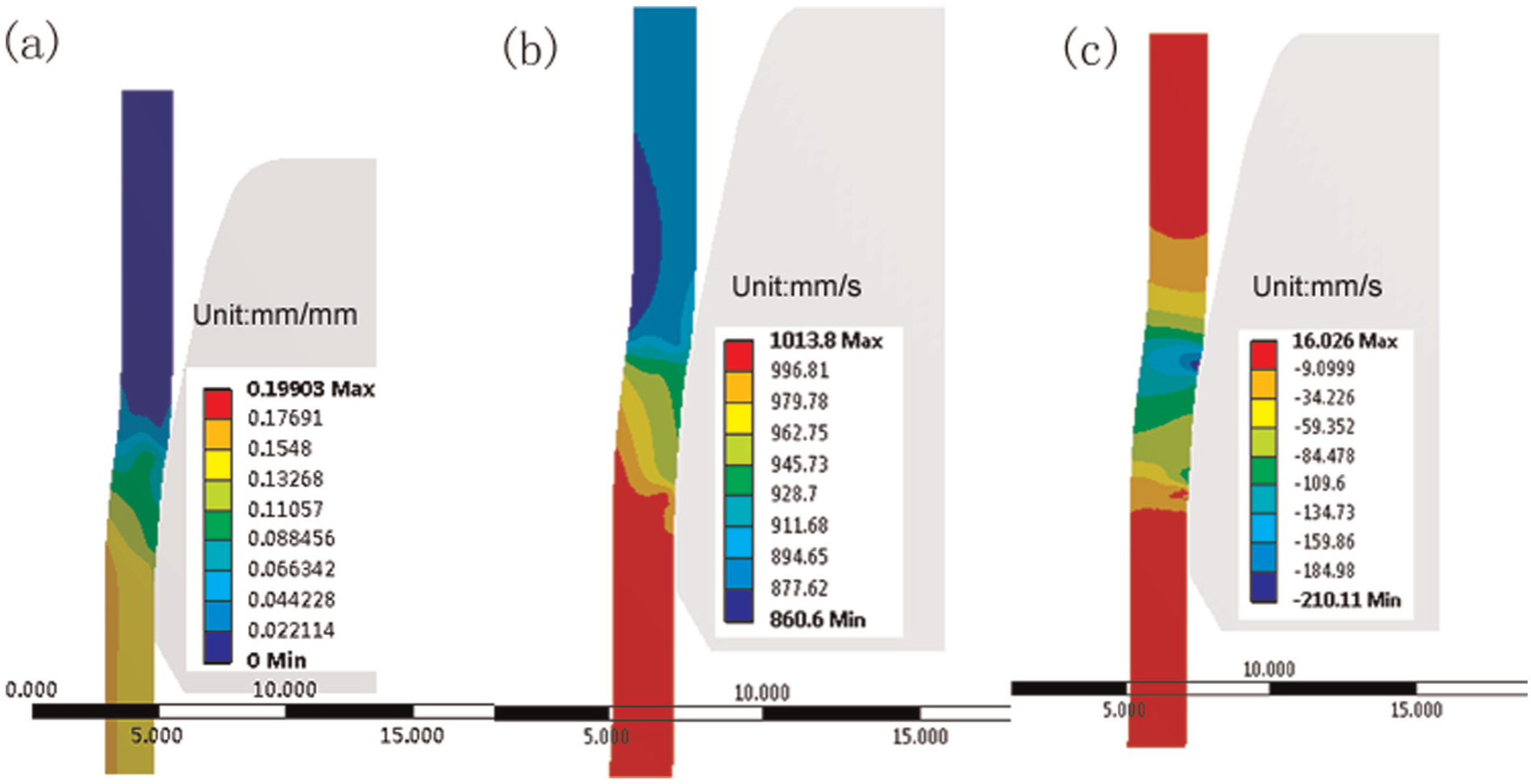
(a) The plastic strain distribution of low carbon steel tube with modified type die, (b) the flowing speed vector graph and (c) cloud graph of the flowing velocity in radial direction.
Without a plug, the inner surface of the low carbon tube can be deformed freely. The flow of metal on cross-section is nonuniform, because the outer surface of the low carbon tube contacting with the drawing die, and it suffers higher flow resistance than inner surface. According to Figure 4(a), plastic strain in the tube continues to increase after the tube enters into the bearing zone. This phenomenon indicates that the tube continues the plastic deformation in the bearing zone. As presented in Figure 4(b), in the reduction zone, there multiple flowing of drawing in both axial direction and shrinking in radial direction, the value of the flowing velocity becomes larger since the sectional area of the drawing die become smaller. The flowing velocity in radial direction (in Figure 4(c)) reaches a peak at the end of the reduction zone. After the tube comes from the reduction zone into the bearing zone, the flowing velocity in radial direction cannot turn to be 0 immediately. Thus, the tube keeps on shrinking in bearing zone until the flowing velocity in radial direction turns to be 0. Therefore, the diameter shrinkage comes into being.
The metal flow is smoother when using a modified type die (Figure 5). Plastic strain distribution in the tube becomes steady when the tube enters into the bearing zone. The value of the flowing velocity becomes larger just like conventional die. The flowing velocity in radial direction reaches a peak at the end of the main reduction zone. Because the angle of the flowing direction becomes much smaller, the velocity in radial direction turns to be decreased when the tube enters into the secondary reduction zone. The value is increased slightly at the end of the secondary reduction zone. However, it is very small when the tube comes into the bearing zone. It can be seen clearly that the metal flowing is smoother with a modified type die when the tube comes from the reduction zone into bearing zone. The final diameter of the low carbon steel tube is calculated from the simulation results: drawn by a conventional die, 12.331 mm; drawn by a modified type die, 12.558 mm. The comparison shows a good advantage of the modified type die.
DOE results
ANOVA
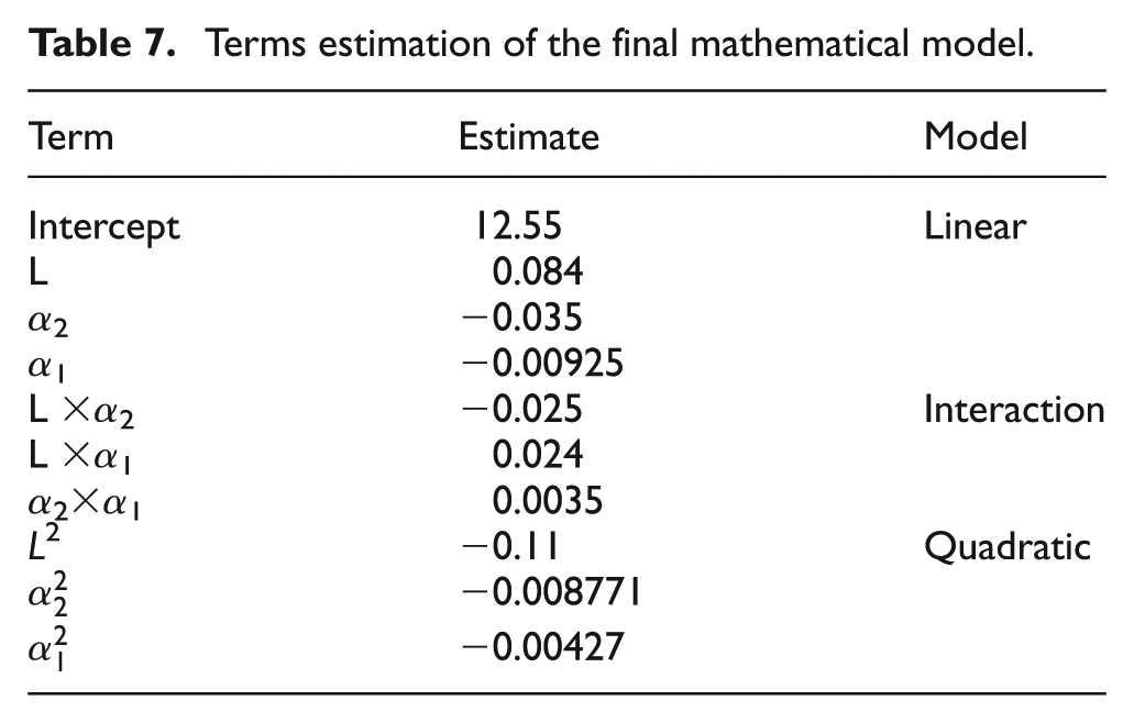
With the Box–Behnken design methodology, major and reciprocal effects of parameters on response function can be easily assessed. The consequential factors in the regression model can be appraised by performing ANOVA.20,21 The ANOVA was used to study the influences of the input parameters on the diameter shrinkage. The resulting ANOVA (Table 6) has been created for the quadratic model. As listed in this table, the significance of each coefficient can be obtained by the “p-value..” The F-value of the quadratic model indicates that the model is significant with only 0.01% chance such that the “Model F-value” could have occurred due to noise. 22 The same table shows the R2, adjusted R2 and predicted R2. A good agreement between the adjusted R2 and predicted R2 was noticed. Values of “p-value” less than 0.05 indicates model terms are significant. In this case A, B, AB, AC and A2 are significant model terms. The comparison of the “F-value” indicates that the most significant parameter is the L. The estimated terms as coefficients of the final mathematical model are given in Table 7.
ANOVA for response surface quadratic model.
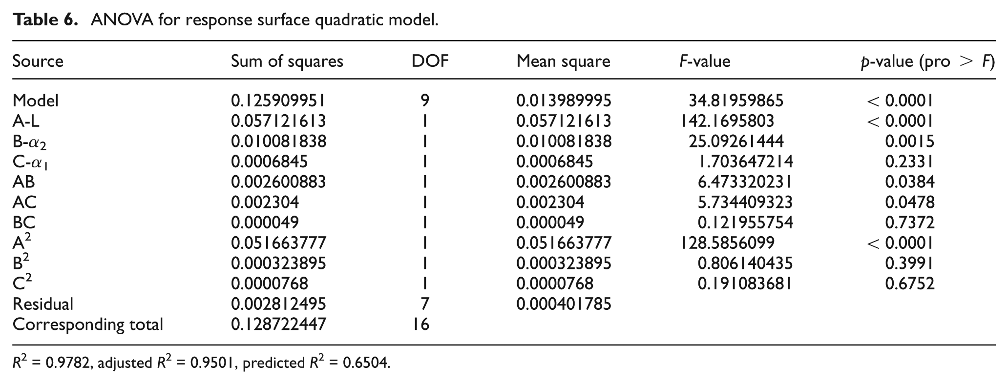
R2 = 0.9782, adjusted R2 = 0.9501, predicted R2 = 0.6504.
Terms estimation of the final mathematical model.
Validation of the RSM models
Figure 6(a) shows the relationship between the actual and predicted values. This figure indicates that the developed models are qualified because the residual in prediction of each response is small since the points lie on a straight line. The plot of the residuals versus the predicted responses (Figure 6(b)) contains no obvious pattern. Hence, it is clear that the model is qualified. Furthermore, to verify the qualification of the developed models, a FEM simulation and an experiment are carried out using the optimum parameters which are predicted by the RSM model. The results are shown in Table 8. It is evident from this table that the models are valid.
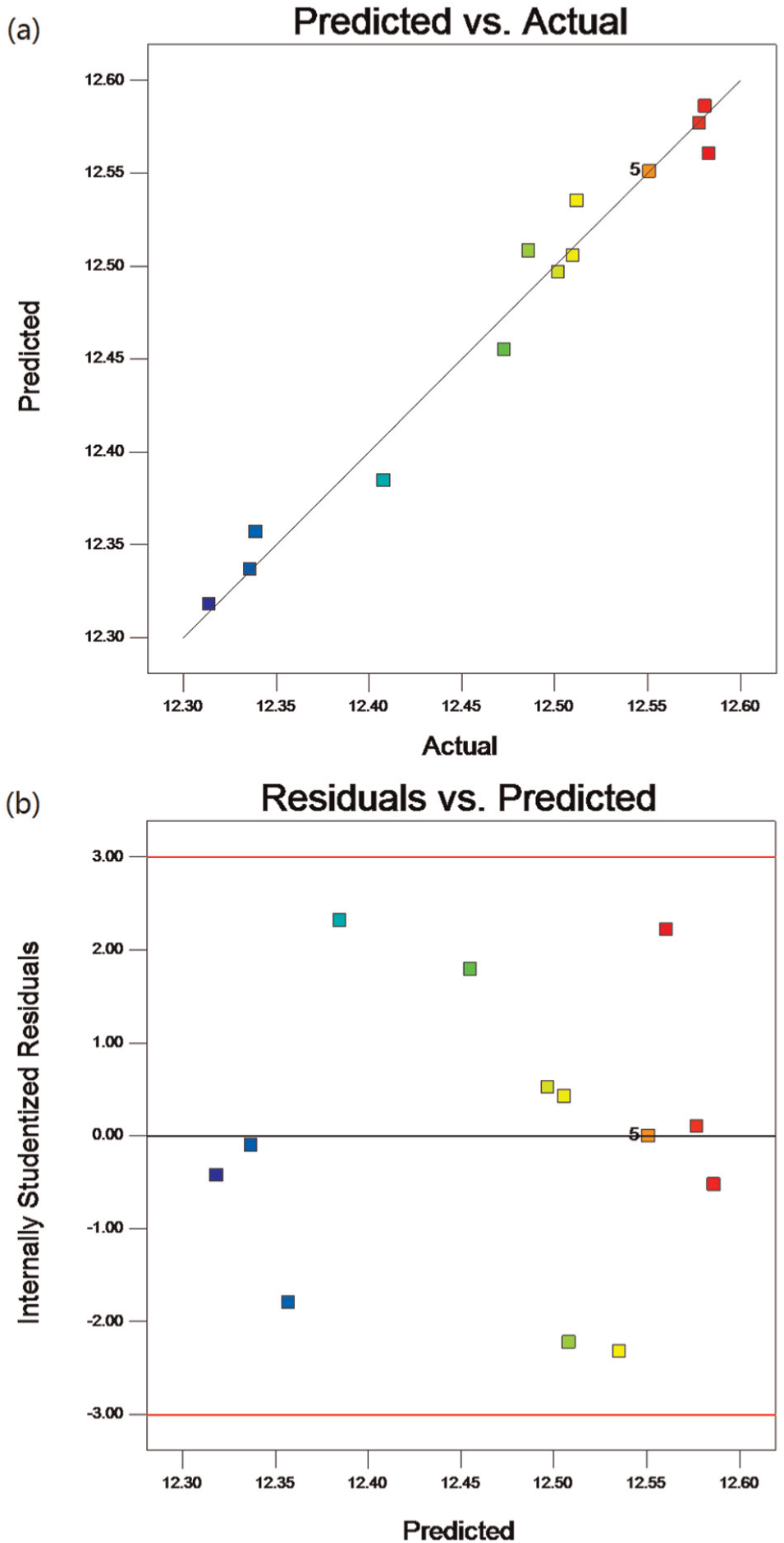
Diagnostic contour plots: (a) the predicted versus actual response and (b) the residuals versus predicted responses.
Confirmation test.
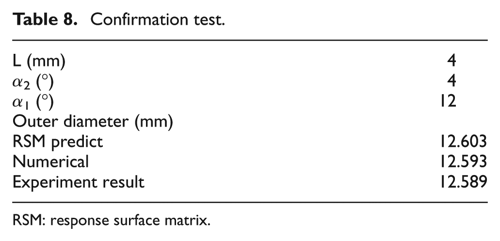
RSM: response surface matrix.
Three-dimensional surface graphs of the predicted results
With the Box–Behnken design methodology, major effects of parameters on response function can be easily assessed. Figures 7 and 8 give the three-dimensional (3D) surface graphs for the predicted outer diameters. According to Figure 7, the increasing of L initially raises the outer diameter. However, as the L is further increased, the value of the out diameter is reduced. In addition, the α2 has no considerable influence on outer diameter when the value of L is lower. At a higher value of L, the higher α2 leads to a larger outer diameter. Consequently, α2 and L have significant effects. The interaction effects of the L and α1 are presented in Figure 8. At a lower value of L, the increasing of α1 raises the outer diameter. However, at a higher value of L, the higher α1 reduce the outer diameter. Consequently, interaction effects of L and α1 are considerable.
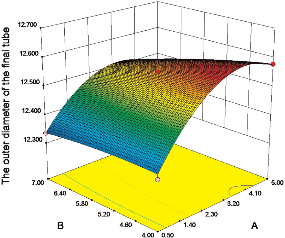
The effects of L and α2.
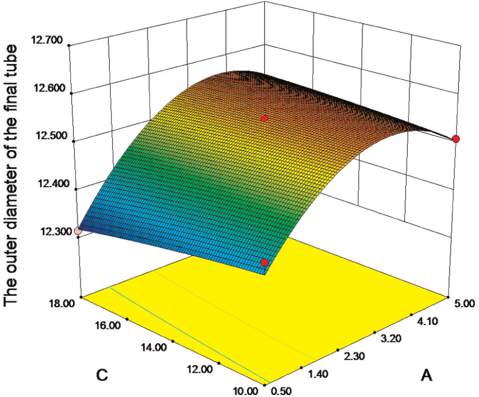
The effects of L and α1.
Drawing performance
The application of the optimal diamond-coated die and the cemented carbide drawing die is made under real manufacturer condition (Figure 9). The criterion for the die change is the quality of the tube surface. 2 The drawing dies must be changed when the scratch appears on the tube surface. This defect on tube surface is unacceptable damage. Figure 10 is a photograph of a tube drawn by the cemented carbide die and the one drawn by the diamond-coated die. A smoother tube surface can be observed from the tube drawn by the diamond-coated die according to this photograph. The work life of cemented carbide drawing die is 9t–10t, while it is 90t–100t for diamond-coated drawing die. Compared with the cemented carbide drawing die, the working lifetime of the optimal diamond-coated die is increased by a factor of 10, the efficiency is greatly improved and dies inventory is decreased. Surface roughness of the low carbon steel tube declines after the 2-ton tube is drawn using the cemented carbide drawing die, due to abrasion wear of drawing die. Thus, the cemented carbide drawing dies need to be polished frequently. Because of good wear resistance of diamond coating, the quality and the surface smoothness of drawn tubes using diamond-coated die can be greatly improved.
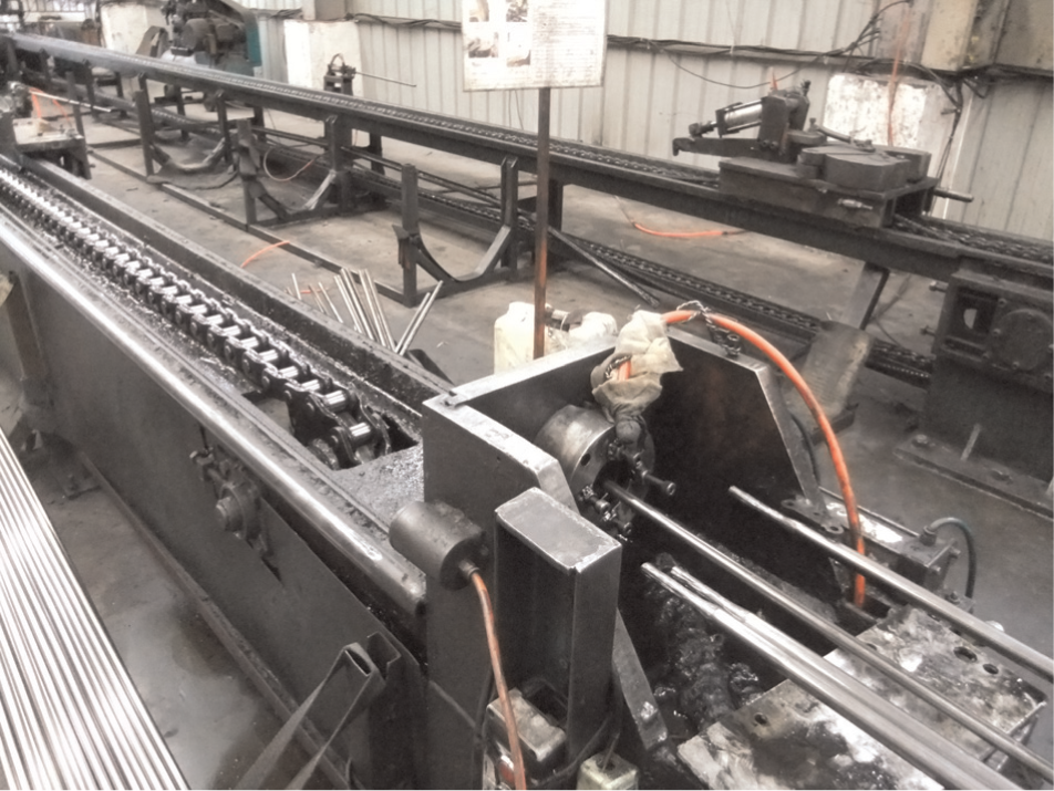
Tube drawing machine.
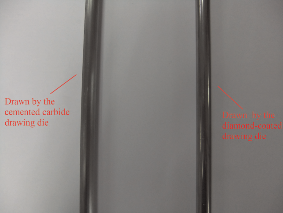
Drawn tubes.
For failure analysis, the drawing dies used in tube drawing after service are cut in longitudinal direction. The wear of the die is analyzed by SEM. According to Figure 11, the failure of cemented carbide drawing die is due to the wear at the reduction zone and bearing zone of the cemented carbide die. Adherence of work piece material on the surface of the worn die can be observed. The wear mechanism is the abrasive wear caused by the removal of the carbide grains from the surface. As shown in Figure 12, the diamond-coated drawing die failure is attributed to the diamond coating peeling off from the die. Before this phenomenon appeared, the diamond coating can protect the substrate from suffering wear due to its extremely high hardness and unique wear resistance. Thus, the working lifetime of diamond-coated die is significantly prolonged.
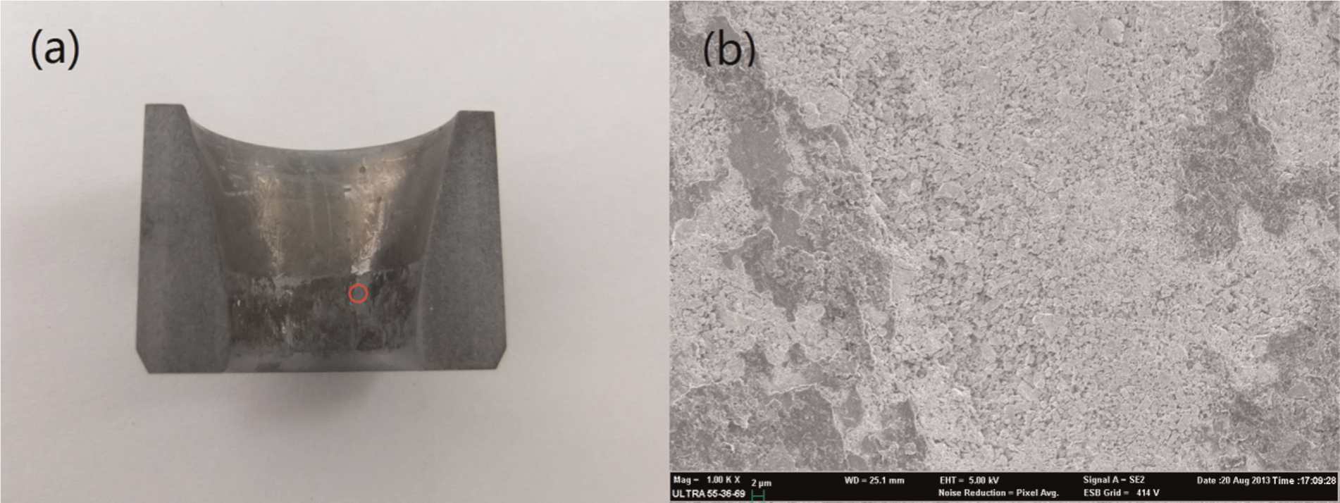
(a) A photograph and (b) an SEM image of a worn cemented carbide die.
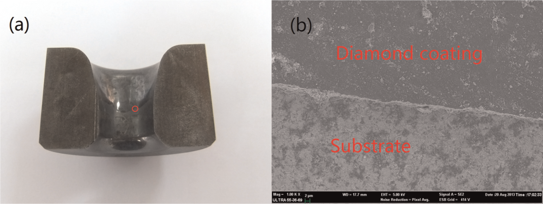
(a) A photograph and (b) an SEM image of a worn diamond-coated die.
Conclusion
A new technology called diamond-coated drawing die is considered as an ideal substitute in cold drawing business. In order to utilize the superior characteristics of diamond coatings toward improving the drawing performance, the modified type drawing die is developed. In this article, drawing processes with a conventional die and a modified type die are simulated to understand the deformation behaviors of the low carbon steel tube. The mechanism of diameter shrinkage is discussed. The outer diameter of the final tube has been validated with a drawing laboratory machine. A coupled set of FEM simulations is conducted to predict the outer diameter in the tube drawing process. The effects of the parameters of tube drawing dies on the dimensional quality of the low carbon tube are quantified by applying RSMs Box–Behnken design. The following conclusions have been made:
The comparison between the conventional die and the modified type die indicated that the metal flowing during the tube drawing process is smoother with a modified type die. This shows a good advantage of the modified type die on diameter shrinkage.
The time in the computational FEM analyses can be remarkably reduced using a response surface methodology.
The ANOVA estimations reveal that the length of the secondary reduction zone L is the most significant parameter influencing the outer diameter of the final tube. After that, the semi-angle of the secondary reduction zone α2 has more influence.
An optimum set is predicted by the RSM model: L = 4 mm, α2 = 4° and α1 = 12°.
An FEM simulation and an experiment are conducted with the optimized set. The experimental result is in good agreement with the FEM simulation and predicted one.
Drawing performances are carried out with the diamond-coated die and the cemented carbide drawing die. The working lifetime is increased by about 10 times.
Footnotes
Declaration of conflicting interests
The authors declare that there is no conflict of interest.
Funding
This research was funded by National Natural Science Foundation of China (no. 51275302, no. 51005154) and the Chenguang Program of Shanghai Municipal Education Commission (no. 12CG11).