
Abstract
This article proposes a new tube forming process designated as ‘elastomer-assisted compression beading’ that is made from a combination of tube bulging produced by elastomer forming and conventional pressworking compression beading. The presentation includes independent determination of the mechanical properties of the tubes, analytical modelling, finite element simulation and experimentation under laboratory conditions with the aims and objectives of identifying the key operating parameters, understanding plastic flow and failure and establishing the formability limits of the elastomer-assisted compression beading process. Results and observations show that the elastomer-assisted compression beading process is capable of producing sound, large-width, compression beads in a broader range of operating parameters than those currently being achieved by means of conventional compression beading. Applications of the proposed elastomer-assisted compression beading process span a wide range of industrial uses involving attachment of tubes to sheets and damping vibrations in air-pressure lines, liquid systems or exhaust tubes.
Introduction
Compression beading is a tube forming process that is accomplished by forcing one tube end towards the other (or the two tube ends towards one another) while leaving a gap opening in-between the dies that hold the tube. Figure 1(a) illustrates a tube before and after being compressed by the upper die and shows its collapse by local buckling that led to the development of a compression bead (
Schematic representation of the conventional (pressworking) compression beading process showing the initial and final positions of the upper die together with a detail of combined inward and outward plastic flow (Detail A) and a detail of outward dominant plastic flow (Detail B).
Compression beads are used in a wide variety of industrial applications. For example, they are used for creating sealing beads for pressure hose applications; for attaching tubes to sheets; for damping vibrations in air-pressure lines, liquid systems or exhaust tubes and for increasing the effectiveness of a sealing by means of O-rings, among other applications.
The pioneering investigations in local buckling were performed in the late 1940s by Shanley
1
who modified the elementary theory of columns due to Euler and proposed the concept of tangent modulus for calculating the critical instability load in plastically deformed cylindrical shells under axial compression. The subject was extensively investigated by the structural mechanics community over the past decades. Hutchinson,
2
for example, studied the influence of geometric imperfections on the buckling behaviour and critical instability loads. Tvergaard
3
analysed the influence of the ratio of the radius to the thickness of the tube
The first materials’ processing-oriented publication in local buckling of thin-walled tubes was authored by Gouveia et al.
6
and made use of varying gap opening conditions. The work identified two main operating parameters: (1) the ratio of the initial gap opening to the reference radius of the tube
Under these circumstances, the aims and objectives of this article are to introduce a new ‘elastomer-assisted compression beading’ process (hereafter referred to as ‘the EACB process’) that makes use of the original idea by Al-Qureshi 9 of using elastomers as pressure-transmitting medium for tube bulging in order to meet the challenge of producing outward dominant, large-width, compression beads in a broader range of operating parameters.
The contribution to knowledge within materials’ processing is threefold. First, the development of a new processing technique that extends the formability limits of conventional compression beading. Second, the combination of experimental, analytical and finite element methodologies to obtain a comprehensive understanding of the behaviour of the tubular specimens across the useful range of operating conditions. Third, the analysis of potential failure modes and associated causes.
The organization of this article is as follows. Section ‘Experimental background’ summarizes the methods and procedures that were utilized in the mechanical characterization of the material, presents the fundamentals of the EACB process and describes the experimental work plan. Section ‘Finite element modelling conditions’ provides a brief overview of the finite element modelling conditions. Section ‘Results and discussion’ presents and discusses the results, namely, plastic flow and failure, and compares the formability limits of the EACB process with those of conventional pressworking compression beading. Section ‘Conclusion’ presents the conclusions and Appendix 1 includes details of the analytical derivation of the internal pressure at the onset of instability.
Experimental background
Mechanical characterization
The tubular specimens utilized in the investigation were cut from commercial S460MC (carbon steel) welded tubes with an outside radius
Mechanical characterization of the S460MC carbon steel tubes: (a) stress–strain curve obtained from tensile and stack compression tests performed at room temperature and (b) load–displacement curves and average critical instability load for the axial compression of tubes between flat parallel platens under two extreme conditions of end fixity.
The critical instability load for the occurrence of axisymmetric local buckling was determined by compressing tubular specimens with 100 mm initial length between flat parallel platens. Two types of tube constraints with extreme conditions denoted as ‘free-ended’ and ‘fixed-ended’ were considered (Figure 2(b)). In case of free-ended conditions, both end surfaces of the tubes were neither laterally supported nor otherwise constrained, whereas in case of fixed-ended conditions, both tube ends were fixed, so that there could be neither lateral displacement nor change in slope at either end.
The experimental load–displacement curves that were obtained for each constraint condition are similar. Thus, assuming constraint conditions during both stages of the EACB process to be neither free-ended nor fixed-ended, the average critical instability load
Methods and procedures
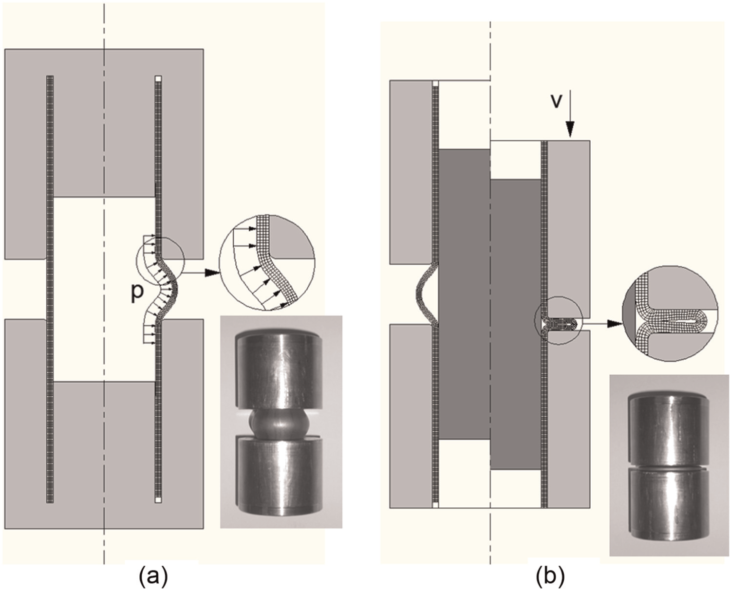
Figure 3 presents a schematic representation of the active tool components that were employed by the new proposed EACB process at the open and closed positions. As seen, the overall process is accomplished by a sequence of two different forming stages. In the first stage, a cylindrical rubber plug with 14.5 mm radius and 50 mm height, made from polyurethane with a Shore hardness of 90A, is placed inside the tube and the tube is bulged (expanded) by compressing the rubber plug with two punches moving in opposite direction with the same velocity
Schematic representation of the: (a) first and (b) second stages of the EACB process.
The active tool components are dedicated to a specific outside radius
During the first stage of the EACB process, the internal pressure
The second stage of the EACB process involved on-line measurement of the applied force and the vertical displacement of the upper die. The aforementioned load cell and a displacement transducer with a resolution of 0.001 mm were employed.
The active tool components were installed in a die set (not shown in Figure 3) that was mounted on the same hydraulic testing machine where the stress–strain curve of the material and the critical instability load of the tubes were determined. The characteristics of slow pressure rise of the hydraulic testing machine match the somewhat delayed deformation behaviour of the rubber plug and ensure adequate forming conditions.
The tubes were first bulged by compressing the rubber plug with the upper and lower punches until failure in order to determine the pressure at the onset of instability
At the end of tube expansion (first stage of the EACB process), the rubber plug was removed and the upper and lower punches were retracted. An internal mandrel was then placed inside the bulged tube, which was subjected to axial compression by means of the upper die in order to produce the desired compression bead. After finishing the second stage of the EACB process and removing the internal mandrel from the tubular parts, selected specimens were halved lengthwise in order to measure the wall thickness variation along the meridional direction of the cross section.
The plan of experiments was designed in order to consider only the influence of the tube slenderness ratio
Geometry of the tubular specimens that were utilized in the experiments with the EACB process (nomenclature according to Figure 3).
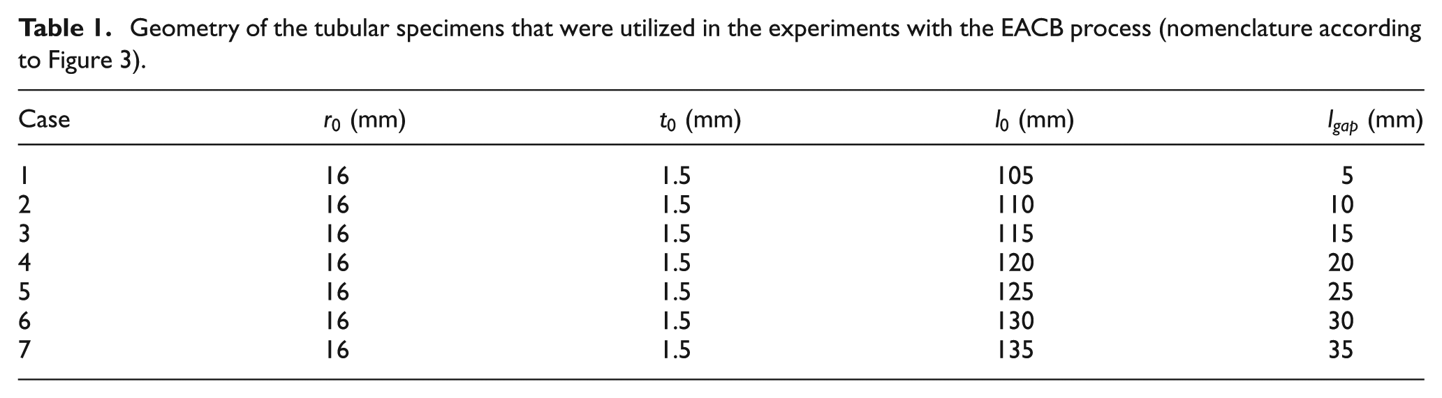
The experiments were done in a random order, and at least two replicates were produced for each test case in order to provide statistical meaning.
Finite element modelling conditions
The finite element modelling conditions that were utilized throughout the investigation made use of the in-house finite element computer program I-form. I-form was developed by the authors and is built upon the irreducible finite element flow formulation, which is based on the following extended variational principle to account frictional effects
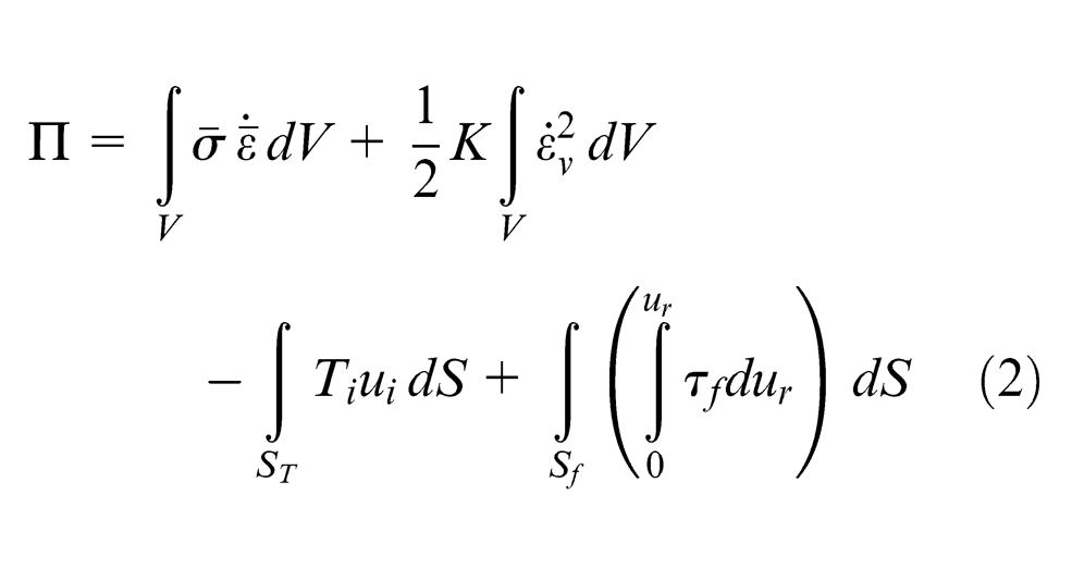
where
Friction is modelled as traction boundary conditions, and the additional power consumption resulting from the rightmost term in equation (2) is determined through the utilization of the law of constant friction
The computer implementation of the extended variational principle
The discretization of the tubular preforms that were utilized in the investigation was performed by means of four-node axisymmetric quadrilateral elements due to rotational symmetry of the EACB process and because no anisotropy effects were taken into consideration. Convergence studies with varying arrangements of quadrilateral elements across the thickness showed that the utilization of four elements was adequate for modelling the distribution of the major field variables and for getting a proper evolution of the load–displacement curve. The tools were considered rigid and were discretized by means of contact-friction linear elements (Figure 4).
Numerical modelling of the EACB process showing the initial and finite element computed meshes at the end of the: (a) first and (b) second stages of the EACB process (case 4 of Table 1). The insets show details of the meshes and pictures of the experiments.
The internal pressure
Results and discussion
Plastic flow and failure
First stage
The observation of crack morphology at bursting for the entire set of tubular specimens that are listed in Table 1 revealed the existence of two different plastic flow mechanisms during the first stage of the EACB process (Figure 5). For large values of the initial gap opening
Influence of the initial gap opening
The experimental values of the internal pressure
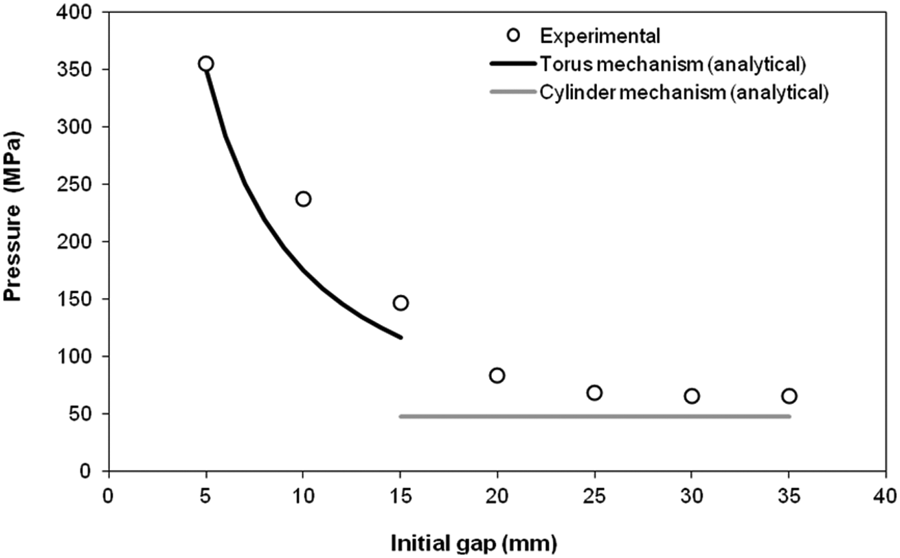
Experimental values and analytical predicted evolution of the internal pressure
The constant values of the internal pressure
Conversely, the sharp variation of the internal pressure
The agreement between the experimental values and the analytical predictions of
In addition, the two different types of experimental results that were observed for case 3 of Table 1 (corresponding to an initial gap opening of
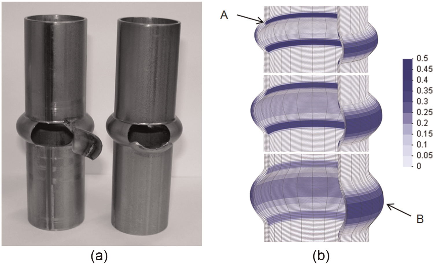
Transition in the mechanisms controlling plastic flow and failure: (a) photographs showing failure by bursting after triggering a vertical and a horizontal crack (case 3 of Table 1) and (b) detail of the finite element–predicted distribution of damage according to the normalized Cockcroft–Latham criterion for cases 2 (top), 3 (middle) and 4 (bottom) of Table 1.
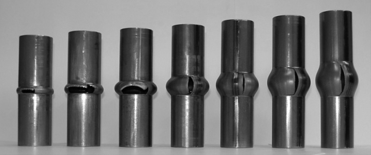
Although the above discussion has been stimulated by crack morphology at bursting, the essence of the first stage of the EACB process relies on the possibility of controlling the amount of compression of the rubber plug by means of the upper and lower punches so that sound bulged tubes can be produced without failure (Figure 8). These tubular specimens are the preforms that are used during the second stage of the EACB process.
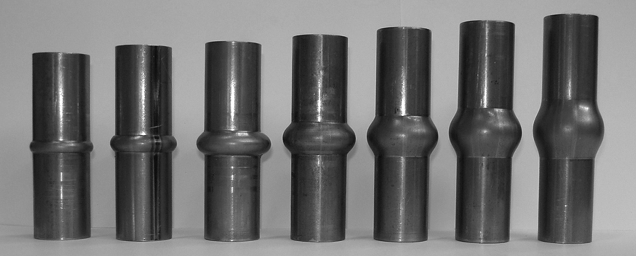
Sound bulged tubes that were produced during the first stage of the EACB process for the entire set of cases that are listed in Table 1.
Second stage
The second stage of the EACB process starts after extracting the upper and lower compression punches and removing the rubber plug. In general, the second stage involves axial compression of the bulged tubes by means of the upper die (refer to Figure 3(b)), and the obtained results are summarized in Figure 9.
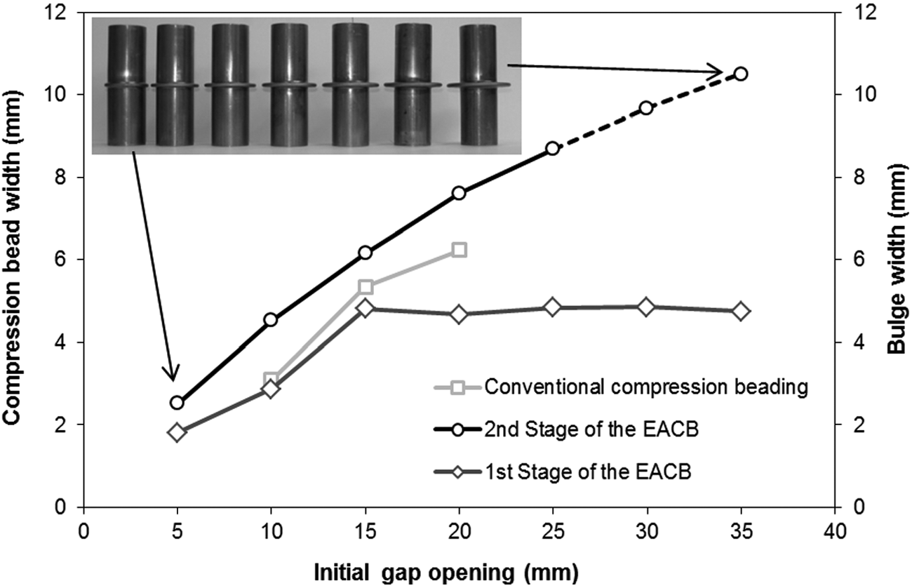
Comparison between the formability limits of the EACB process and the conventional compression beading process. Insets show photographs of the specimens produced by the EACB process.
As seen in Figure 9, the formability limits of the EACB process successfully extend those of the conventional process by allowing the formation of compression beads under initial gap openings below and above the former minimum and maximum thresholds. On the other hand, results also show that the final width of the compression beads
The saturation of the maximum bulge width to a value of approximately
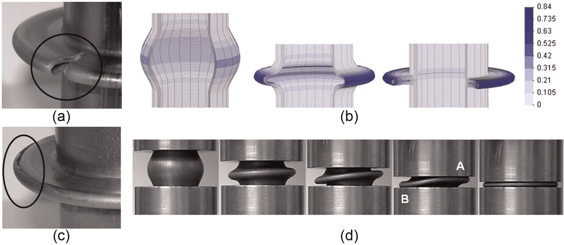
Failure by cracking during the second stage of the EACB process (case 6 of Table 1): (a) photograph showing failure by cracking along the meridional direction, (b) finite element–predicted evolution of ductile damage (Cockcroft–Latham normalized criterion) for a test case corresponding to (a), (c) photograph showing failure by cracking along the circumferential direction and (d) photographs showing the evolution of the compression bead presented in (c) during the second stage of the EACB process.
The influence of plastic flow on the variation of thickness along the cross section of a tubular specimen at the end of the first and second stages of the EACB process is illustrated in Figure 11. The meridional distance is measured from the upper end to the equatorial region of the tubular specimens. The initial flat region of the graphic corresponds to nearly unstrained material placed in the cylindrical region of the specimens, and the final thickness in this region remains practically identical to the initial thickness of the tubes. The subsequent sharp decrease in thickness that is observed at the end of the first stage of the EACB process is due to tube bending around the corner radius
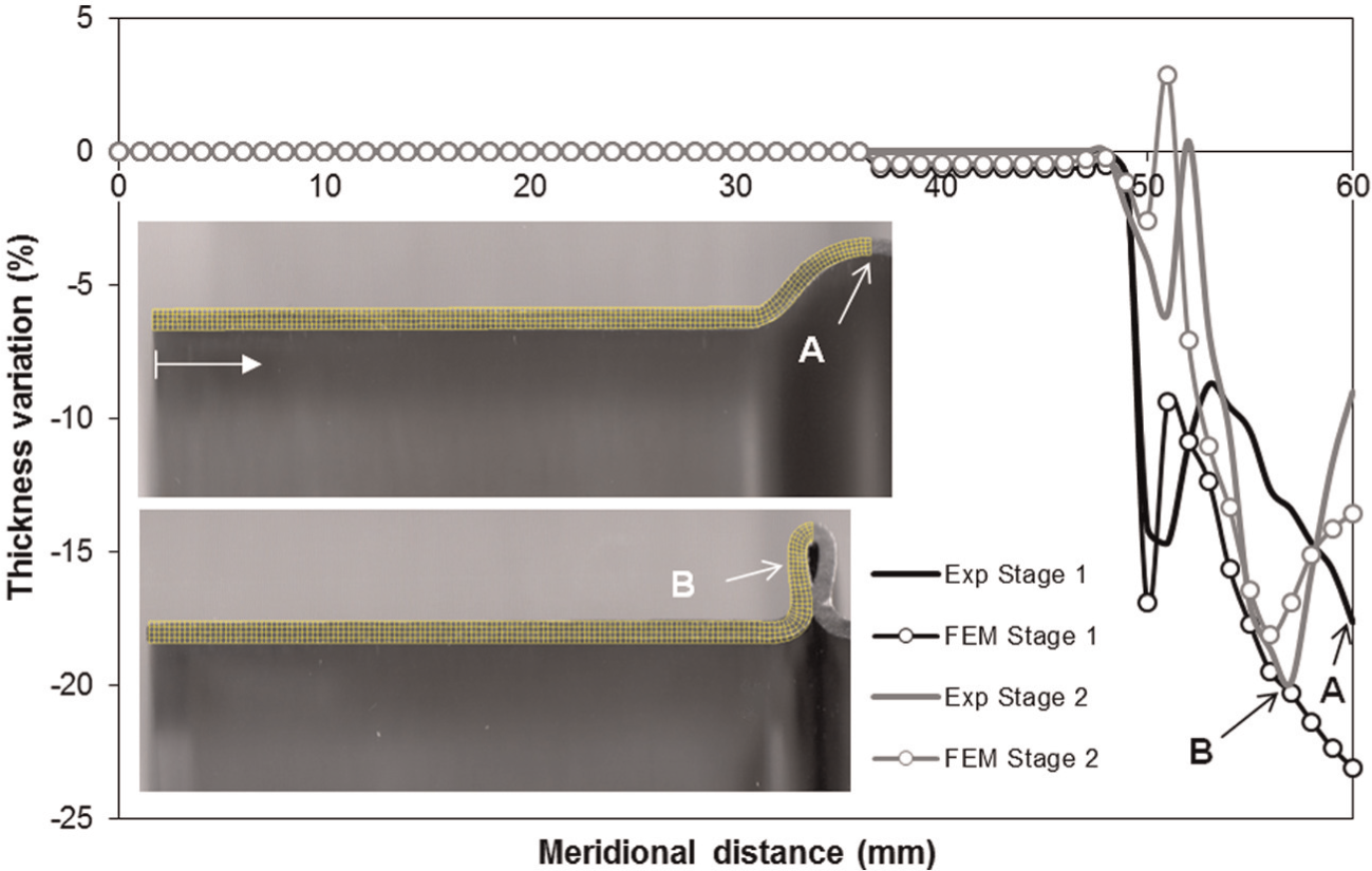
Experimental and finite element–predicted variation of thickness along the meridional direction for case 4 of Table 1 in the cross section of tubular specimens corresponding to the end of the first and second stages of the EACB process.
The most interesting result associated with the second stage of the EACB process is the replacement of the equatorial plane by the adjacent zone placed immediately before (refer to ‘B’ in Figure 11), as the region of the tubular specimens where thickness variation is larger. This is attributed to a combination of thinning due to bending in ‘B’ and thickening (around 9% increase) at the equatorial plane corresponding to former point ‘A’.
The result of overlapping finite element computed meshes with the cross section of the experimental tubular parts corresponding to the end of the first and second stages of the EACB process (refer to Figure 11) corroborates the overall good agreement that was found between experimentation and numerical simulation (Figure 11).
Pressure and forming loads
Figure 12 shows a typical experimental and finite element–predicted evolution of the internal pressure with the radius of the bulged tube during the first stage of the EACB process. As seen, the internal pressure
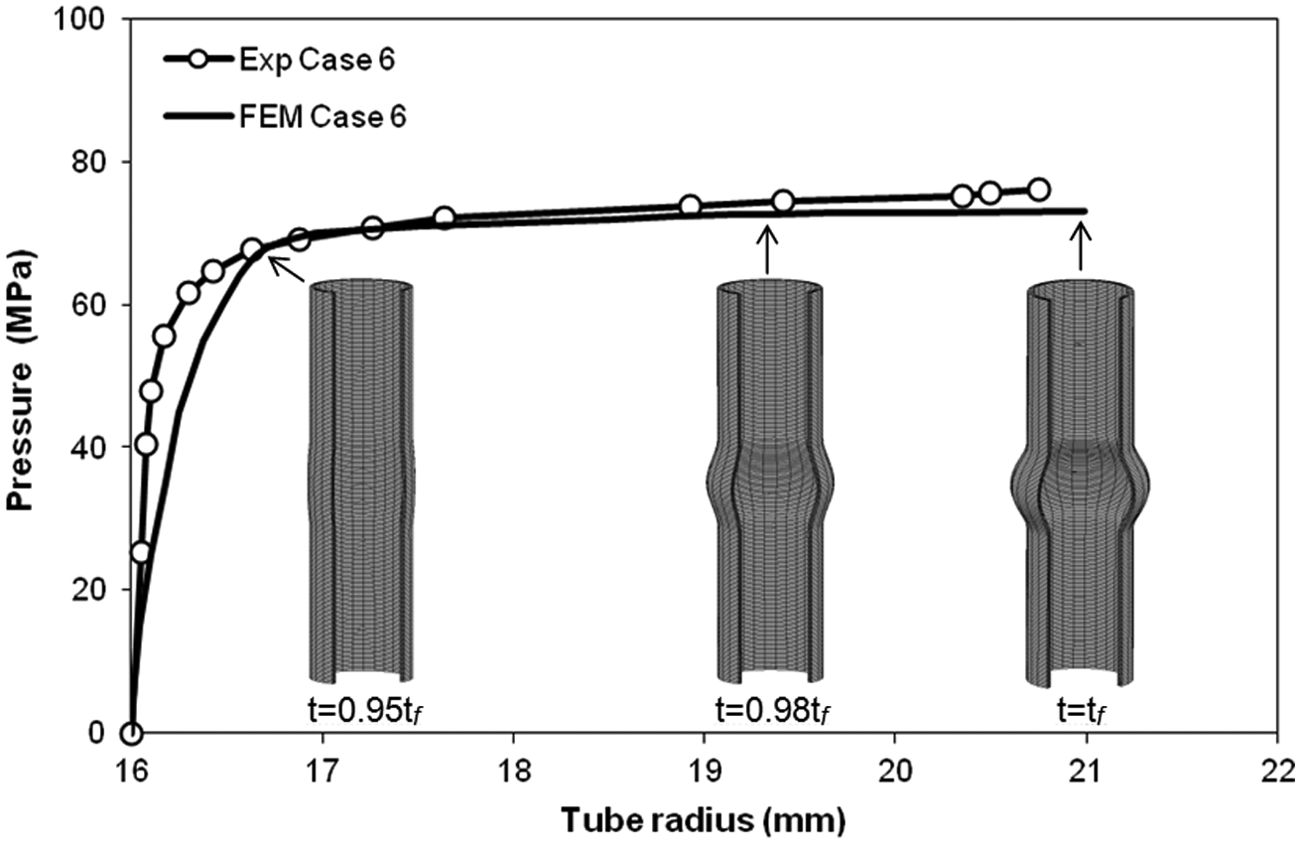
Experimental and finite element–predicted evolution of the internal pressure with the radius of the bulged tube (case 6 of Table 1).
Finally, Figure 13 shows the experimental and finite element–predicted load–displacement curves corresponding to entire set of test cases listed in Table 1, for the second stage of the EACB process. As seen, all test cases apart from case 1 show three different plastic deformation stages (refer to the regions labelled as ‘A’, ‘B’ and ‘C’ in case 3).
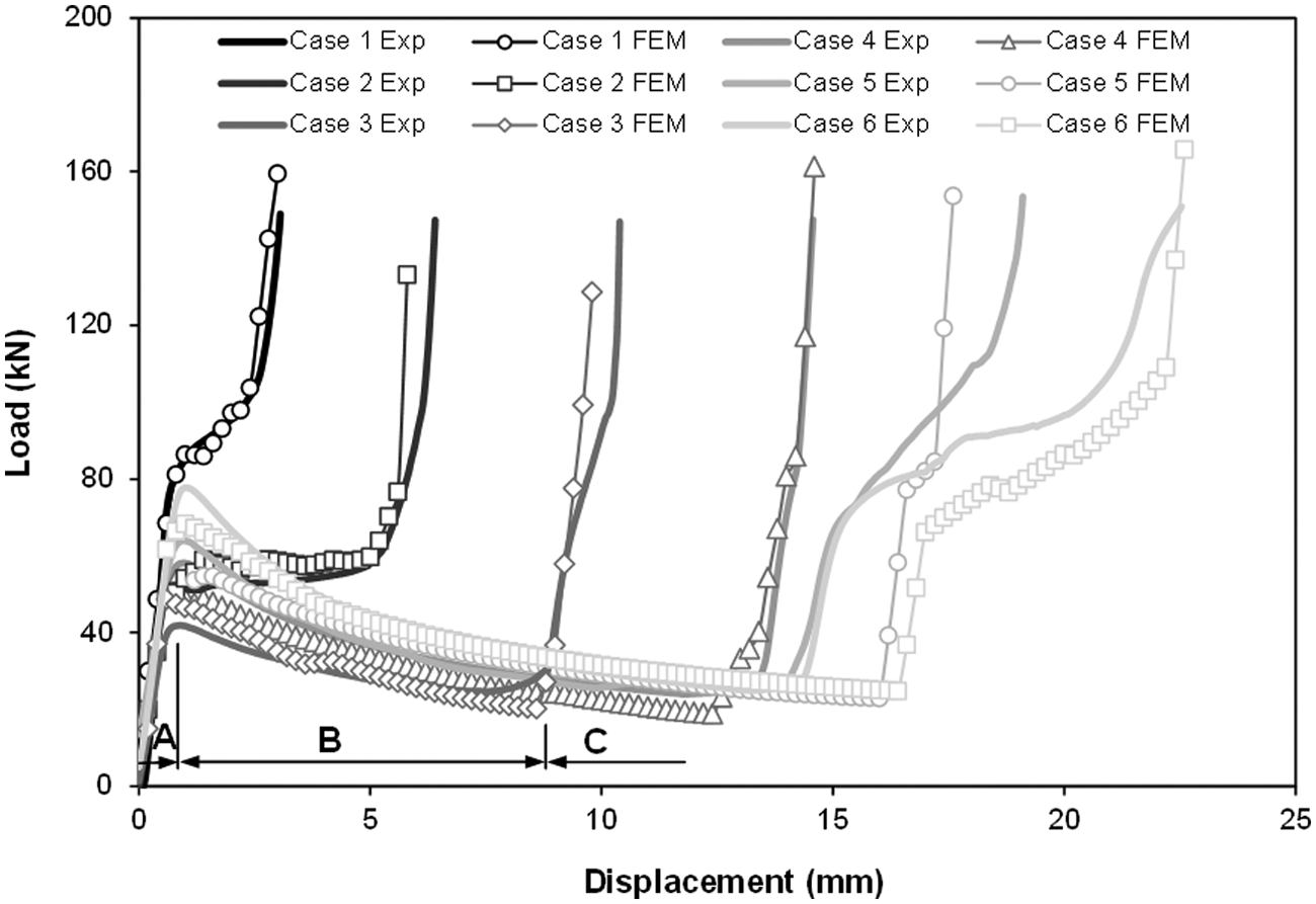
Experimental and finite element–predicted evolution of the load–displacement curves for the entire set of test cases listed in Table 1 during the second stage of the EACB process.
The first stage (region ‘A’) is characterized by a steep increase in the forming load up to values of 40–80 kN as the bulged tube is axially loaded and the compression bead starts to develop. In the second stage (region ‘B’), the compression bead grows under a falling load for all test cases apart from case 1. Case 1 presents a monotonic increase in the forming load due to a small value of the initial gap opening that leads to the development of small-width compression beads. Results also show that the load–displacement curve corresponding to case 6 presents the lowest drop in load and the largest overall displacement. This is attributed to the fact that case 6 is shaped under the largest initial gap opening
The third stage (region ‘C’) is characterized by a sharp increase in load requirements caused by the enclosure of the compression beads between the upper and lower dies. The agreement between experimental and finite element–predicted evolutions of the load–displacement curve is generally good for the entire set of operating parameters corresponding to Table 1.
Conclusion
This article is about combining tube bulging produced by elastomer forming and compression beading produced by conventional pressworking into a new materials’ processing technique. The proposed EACB process extends the formability limits of compression beads by allowing the utilization of initial gap openings
The deformation mechanics of the first and second stages of the EACB process were investigated by means of analytical modelling, numerical simulation and experimentation. Plastic flow and failure during the first stage of the EACB process were explained by the classical solution of a thin-walled cylinder shell with open ends under internal pressure and by a new approximate solution of a thin-walled toroidal shell under internal pressure. The new solution was appropriate for understanding the critical values of the internal pressure
Footnotes
Appendix 1
Declaration of conflicting interests
The authors declare that there is no conflict of interest.
Funding
This work was partially supported by the Portuguese Foundation for Science and Technology under the research contract PEst-OE/EME/LA0022/2011. This work was also supported by MCG – Mind for Metal, Carregado, Portugal.