
Abstract
The tube bulge forming process is a very effective means to manufacture a complex part as one piece, without the need for additional processes, such as welding and joining. Since one-piece components can endure higher applied loads, they should be considered in the design and manufacture of structural parts. The head tube of a bicycle is one such example, being a four-directional multi-joint component that is also subjected to the highest external load of all bicycle parts. A head tube is therefore ideally fabricated as a singular piece using a suitable process such as tube bulge forming. Commercial Ti-3Al-2.5V alloy tube was selected for this study, as it represents a standard material for Ti-alloy-body bicycles. Finite element simulation is used to predict defects resulting from inappropriate gas blowing conditions and to calculate the optimum forming conditions. Based on the results of finite element analysis and practical experiment, an optimized pressure curve for the bulging of a bicycle head tube is proposed. The effect of microstructural change by deformation is also investigated to predict possible defects in the large-scale deformation of bulged head tubes.
Introduction
Tube hydroforming technology has matured over the past several years, as it offers a higher quality at a lower cost for many complex parts. 1 Notable achievements include the development of a simple X- and T-branch tube hydroforming process by Ray and Mac Donald, 2 Suwat’s and Giuseppe’s study into Y-shape forming, and Hossein’s optimization of the T-type tube bulging process.3–7 Models with a three-connector shape were used in all these examples, with the tubes being pushed from an outer section into an inner section to be deformed with a uniform thickness. Tube hydroforming is perfectly suitable for obtaining uniform thickness; however, the available materials are somewhat restricted within narrow limits due to the low temperature of available working fluids. Consequently, Ti-alloys cannot be deformed by tube hydroforming processes as their typical forming temperature of over 800 °C is well in excess of the most working fluids. Both experiment and finite element (FE) analysis of multi-tube bulging of Ti-4.5Al-3V-2Fe-2Mo alloy were conducted by gas blow forming process at 825 °C forming temperature. 8
Tube bulge forming by gas blowing is a very effective method to manufacture a complex one-piece part, without the need for further processing such as welding and joining. Since one-piece components can endure higher applied loads than multi-piece types, their use should be maximized in the design stage. The head tube of a bicycle is a perfect example of this, being a four-directional multi-joint component with the highest external load of all the parts in a bicycle. Tube bulge forming by gas blowing is suitable for the fabrication of a one-piece head tube, especially where high forming temperature materials such as Ti-alloys are used.
In this study, a tube bulge forming process is developed for the fabrication of a one-piece multi-joint head tube for a Ti-alloy-body bicycle. As shown in Figure 1, commercial Ti-3Al-2.5V alloy tube is generally used in the manufacture of Ti-body bicycles, and so a commercial Ti-3Al-2.5V alloy tube (2.1 mm thickness) was selected for all experiments and FE analysis. The flow stresses of Ti-3Al-2.5V alloy tube were measured at various temperatures, along with the strain rate, by high-temperature tensile tests. The ductile fracture criteria were then calculated by a simple T-shape bulge test and FE analysis. These data were used to calculate the pressure–time for the bulging of a one-piece Ti-head tube at high temperature. A suitable pressure–time curve is something that needs to be calculated in order to prevent the occurrence of defects during forming. FE simulation based on ductile fracture criteria was also used to predict some potential defects that can occur due to inappropriate gas-pressing conditions. Based on FE analysis and practical experiments, suitable gas blow forming conditions were determined for the fabrication of a one-piece Ti-head tube intended to replace the conventional three-piece welded head tubes currently in use.9–10
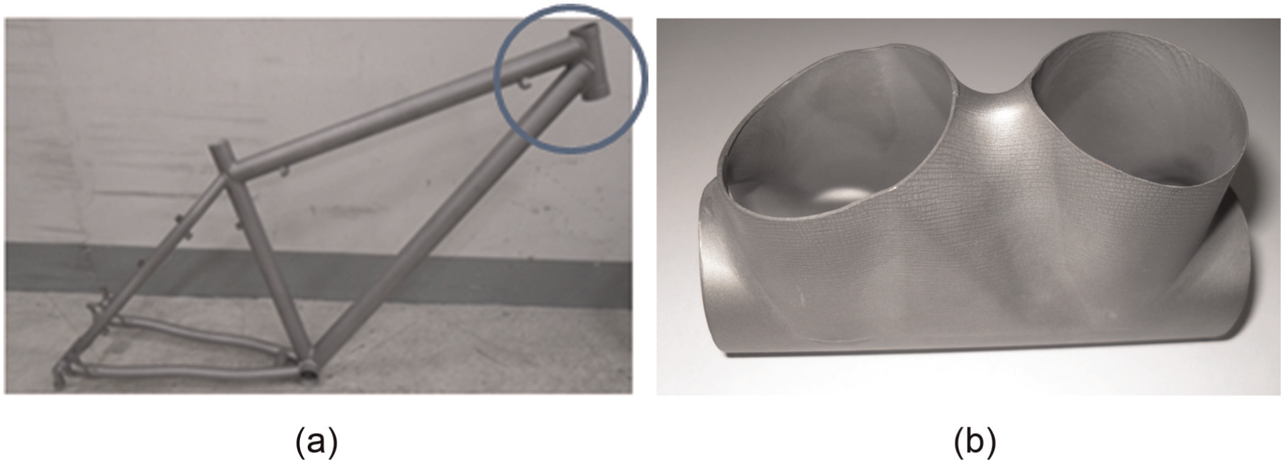
Ti-3Al-2.5V body of bicycle with (a) welded head tube and (b) one-piece-type head tube.
One-piece-type head tube design
The one-piece head tube was modified from a conventional three-piece welded-type taking into consideration assembly and strength requirements. The head tube is joined to two supporting tubes, and as such, a minimum contact length at the joined section along different angles is required to sustain the requisite bonding length and strength under various load conditions. In addition, an undercut section was incorporated to allow extraction of the formed part from the forming tools. The original welded three-piece part and modified one-piece part are shown in Figure 2.
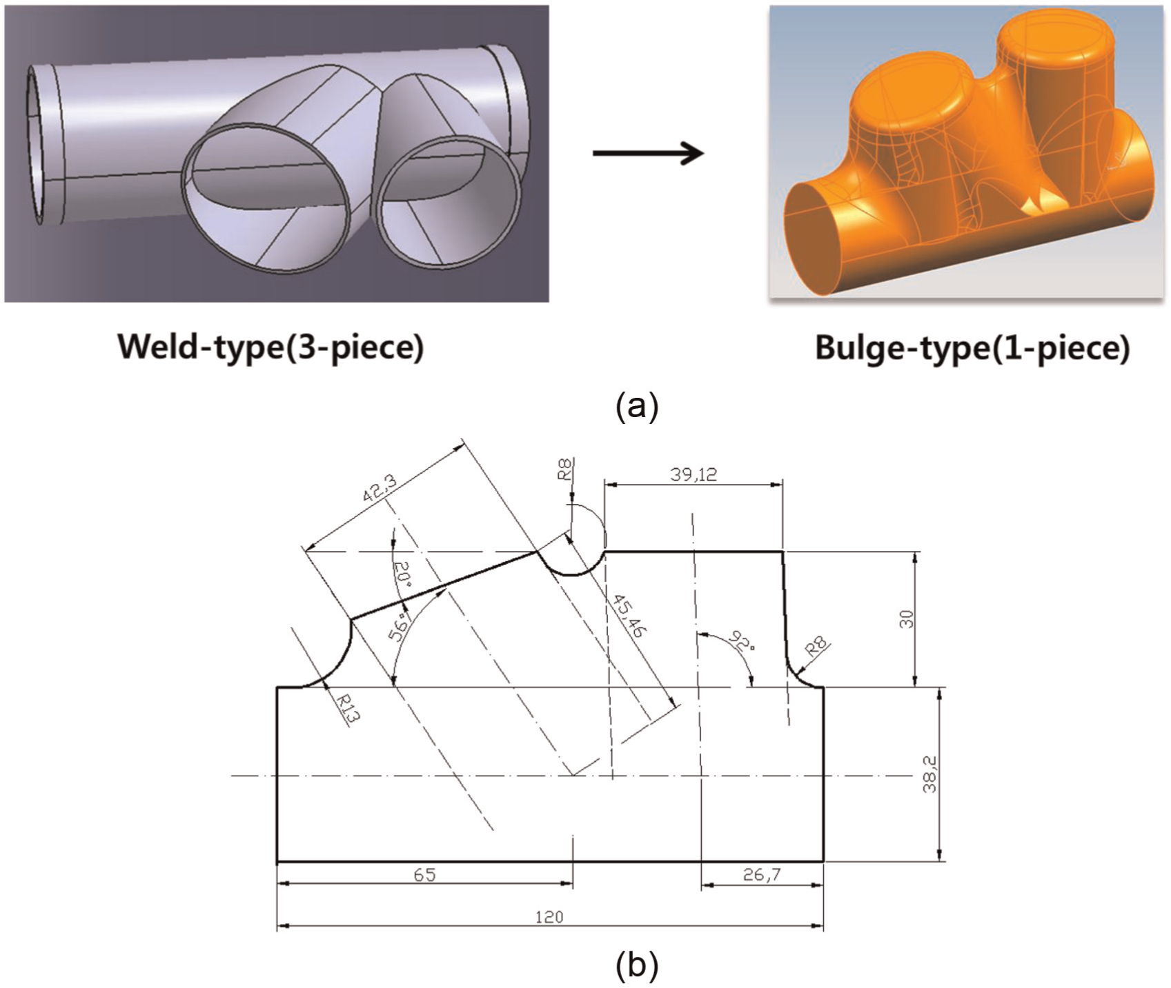
3D model of head tube redesigned for fabrication by tube bulging: (a) redesigned head tube 3D model and (b) 2D drawings of redesigned head tube.
Gas blow forming of head tube
Characteristics and material for head tube
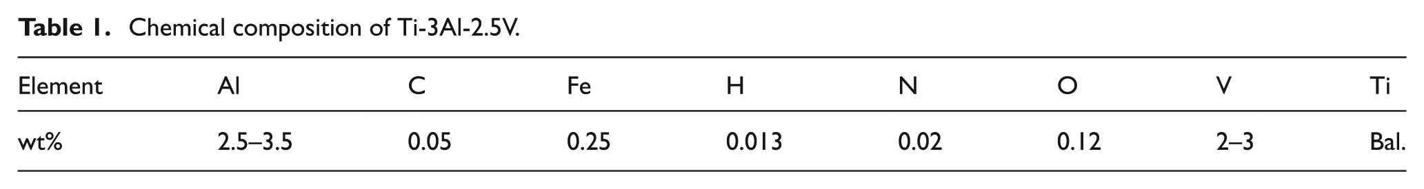
The Ti-3Al-2.5V alloy used in this study is 1.6 times heavier than aluminum and 0.6 times lighter than steel. The chemical composition is shown in Table 1. It has a higher melting point and lower thermal conductivity than steel, and so the forming temperature is generally higher than for other light metals. Initially, titanium alloys were mainly used in the aviation industry, but their use has steadily widened to include eye-wear, bicycles, medical implants, and so on.
Chemical composition of Ti-3Al-2.5V.
The microstructures were characterized by optical microscopy (OM) and scanning electron microscopy (SEM). Grain size was measured for quenched as-received specimens, as well as after bulge forming tests. In addition, backscattered electron-scanning electron microscopy (BSE-SEM) was used for rapid phase discrimination, by illustrating contrasts in composition with multiphase samples.
Flow stresses were measured by high-temperature tensile testing to survey high-temperature deformation characteristics, with these subsequently used as the input data for FE simulation. The high-temperature tensile test was conducted at temperatures of 800 °C and 850 °C with strain rates of 0.01 s−1 and 0.001 s−1, respectively. The measured flow stress data are shown in Figure 3.
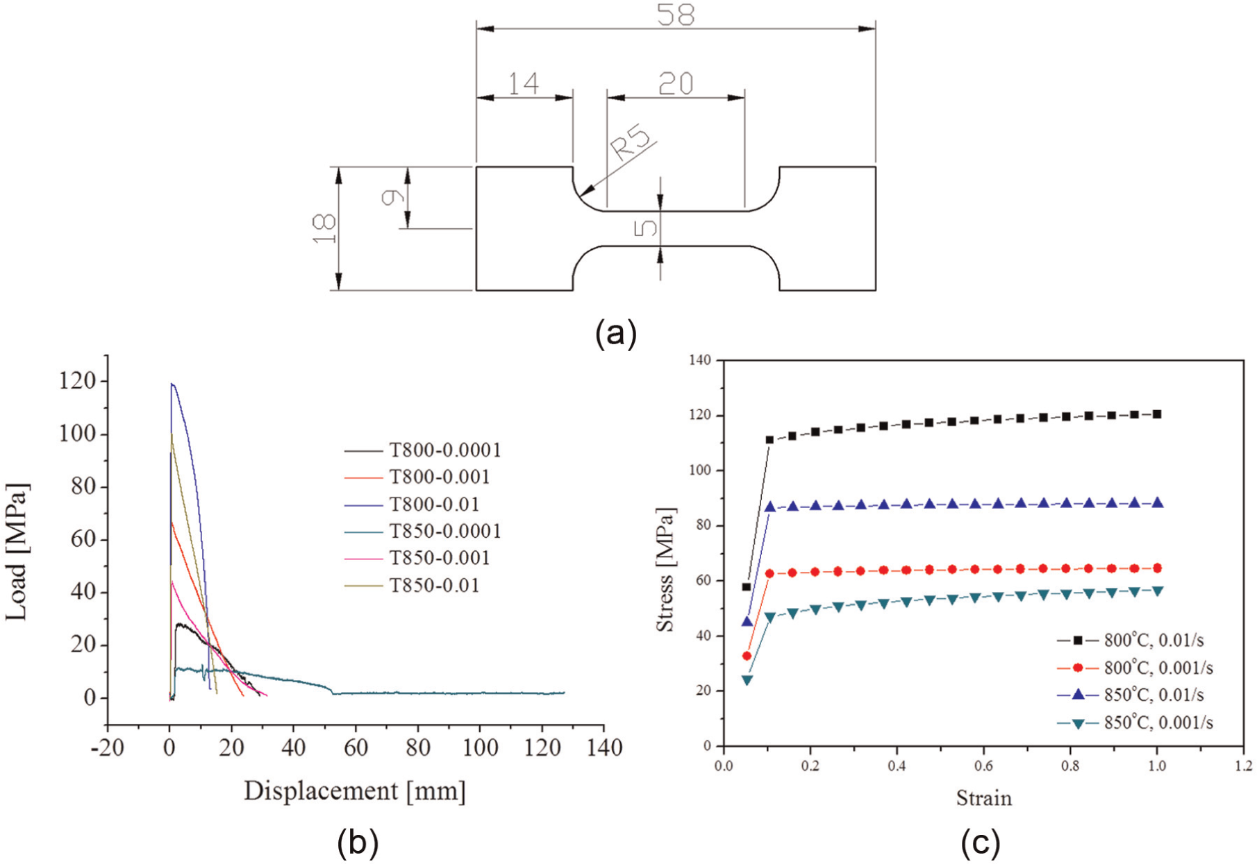
Load–stroke data of Ti-3Al-2.5V measured by high-temperature tensile test and flow stress curve for FE simulation: (a) tensile test specimen, (b) measured load–displacement curve, and (c) flow stress curve for FE simulation.
Tube bulging of head tube by gas blow forming
The gas blow forming process was investigated to bulge a Ti-alloy head tube as a one-piece part. This process must be conducted under adequate pressure–time conditions, and at a high temperature of 850 °C. Figure 4 depicts a diagram of the gas blow forming machine used.
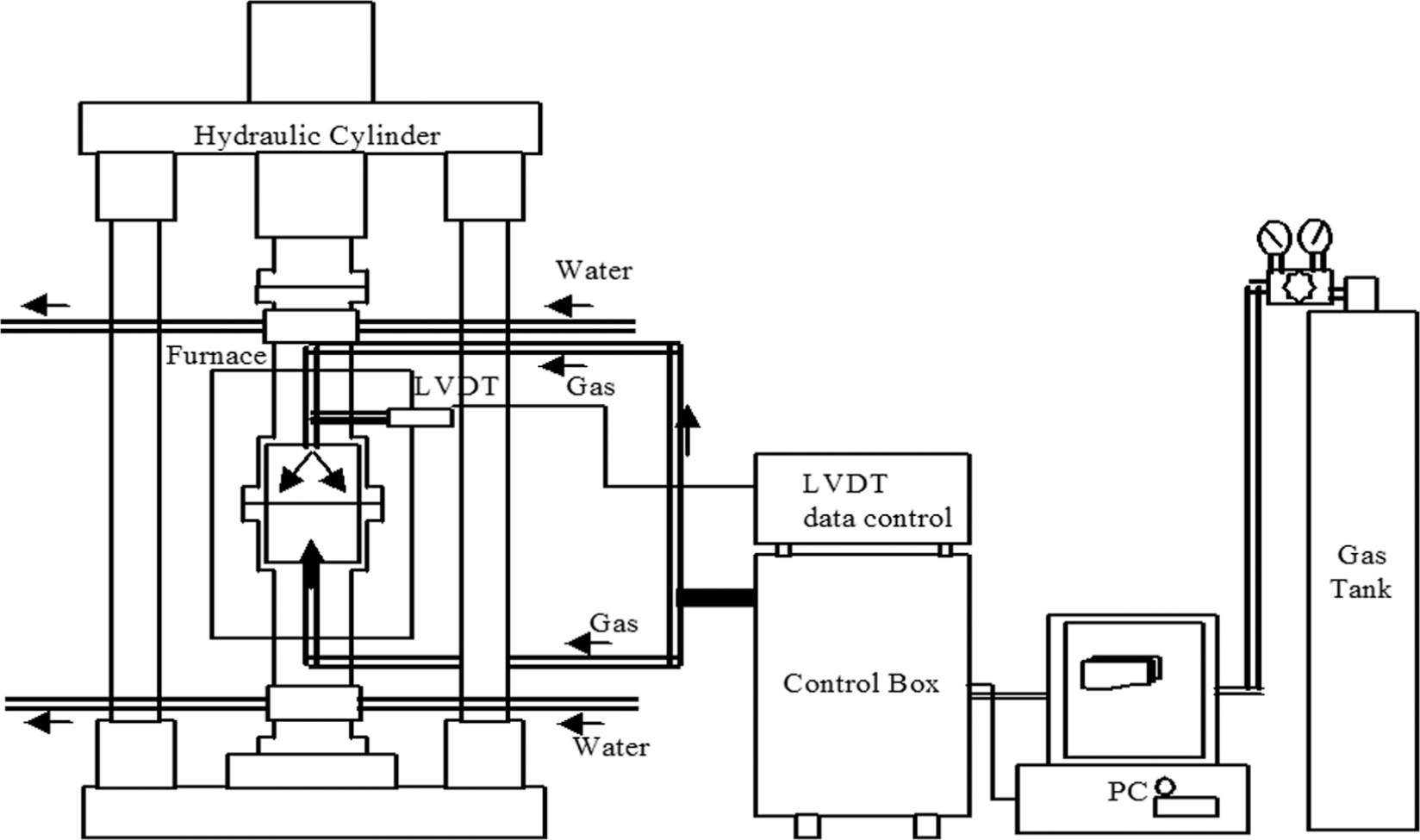
Diagram of gas blow forming machine; LVDT: Linear Varaible Differential Transformer.
Tools for the head tube were designed and machined as shown in Figure 5(a). The tools were divided into two parts for easy extraction of the formed tube, consisting of an upper and a lower die. Figure 5(b) shows the resultant tube formed by the gas blow forming process. No forming defects were identified, and the as-formed tube was subsequently machined to final shape, as shown in Figure 1(b).
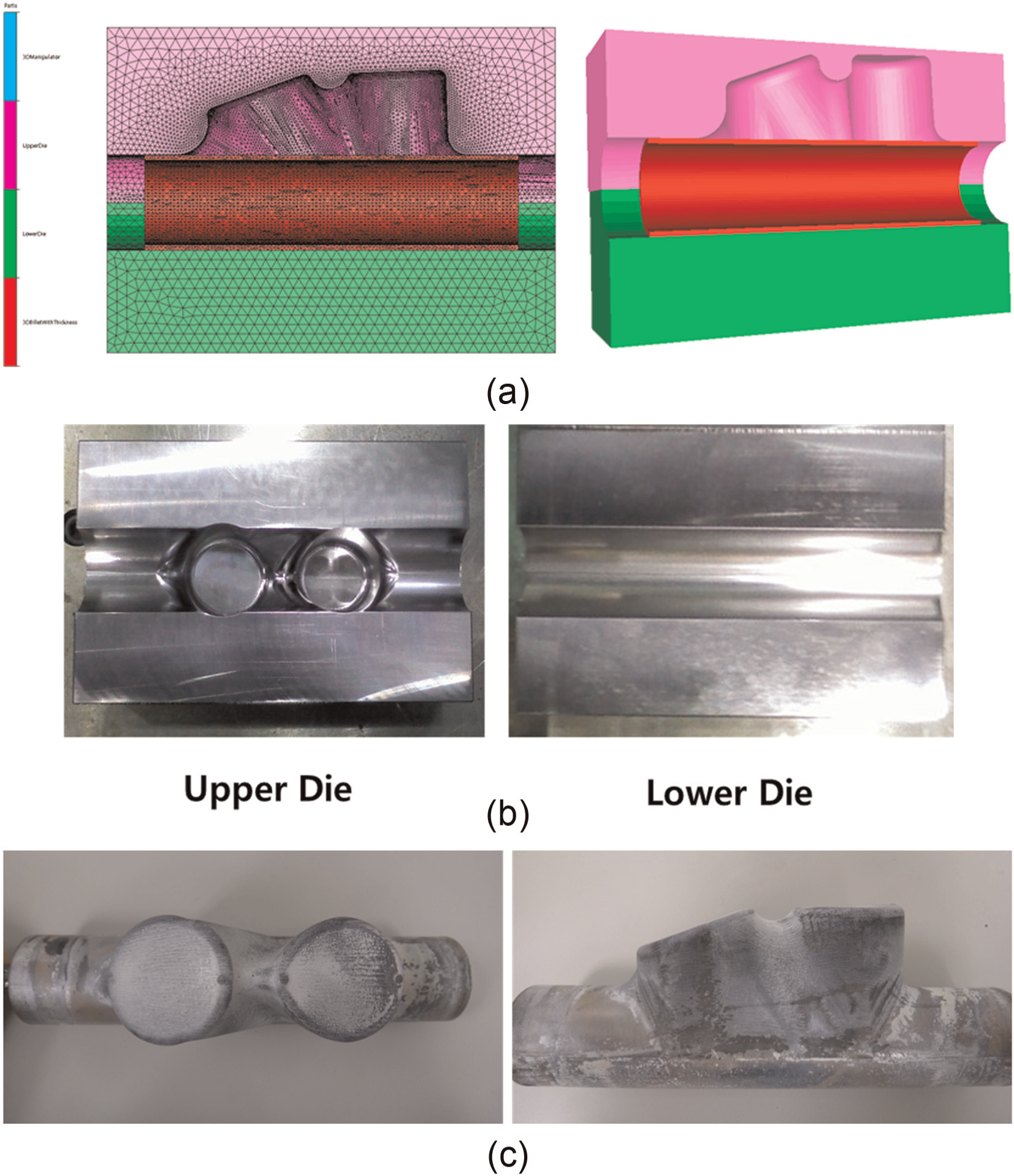
3D model, dies, and as-formed part for tube bulging of head tube: (a) FE model for tube bulging of a one-piece head tube, (b) dies for tube bulging of a one-piece head tube, and (c) one-piece head tube formed by gas blow forming.
Analysis of formed tube
Microstructures of formed tube
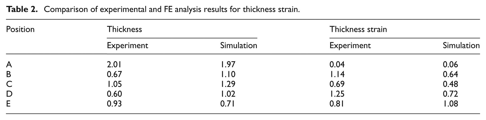
The microstructure was observed by OM and SEM, as shown in Figures 6 and 7. The microstructure of the as-received material comprised an equiaxed α grains over the entire material, as shown in Figure 6(a). The grain size varied from 5 to 10 μm, with an average size of 6.3 μm. Following the tube bulge forming process, the average grain size increased, 14.5 μm, as shown in Figure 6(b). Generally speaking, α Ti-alloys exhibit satisfactory strength and good creep resistance, but suffer from poor formability. Conversely, β alloys possess good formability, but suffer from a lack of creep strength. The Ti-3Al-2.5V alloy is a unique α–β alloy, which at times is referred to as one-half of a Ti-6Al-4V alloy and falls into the category of near α-titanium alloys. The microstructure was also observed by BSE-SEM (Figure 2). In Figure 7(a), the microstructure of the as-received material shows very fine acicular α in accordance with the literature.11,12 Due to the high temperature of the tube bulge forming process, the microstructure is altered to equiaxed α with an intergranular β-phase structure, as shown in Figure 7(b). The intergranular β-phase was formed on the grain boundaries of the equiaxed α grain boundary and the transformed β fraction occupying 1.6 vol%. The near α-titanium alloys generally possess a microstructure consisting of α grains with β distributed at the grain boundaries or at triple points. The degree of microstructural change can be evaluated by the change in thickness and strain, as shown in Table 2.
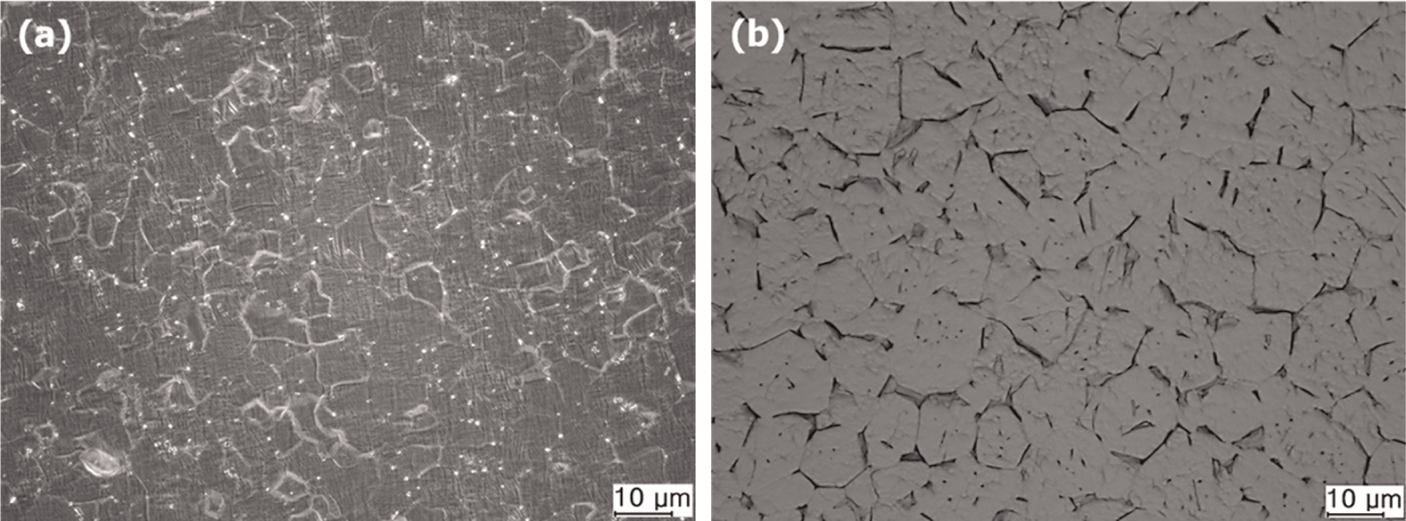
Optical microstructure images of the microstructure of etched Ti-3Al-2.5V: (a) as-received and (b) after bulge forming.
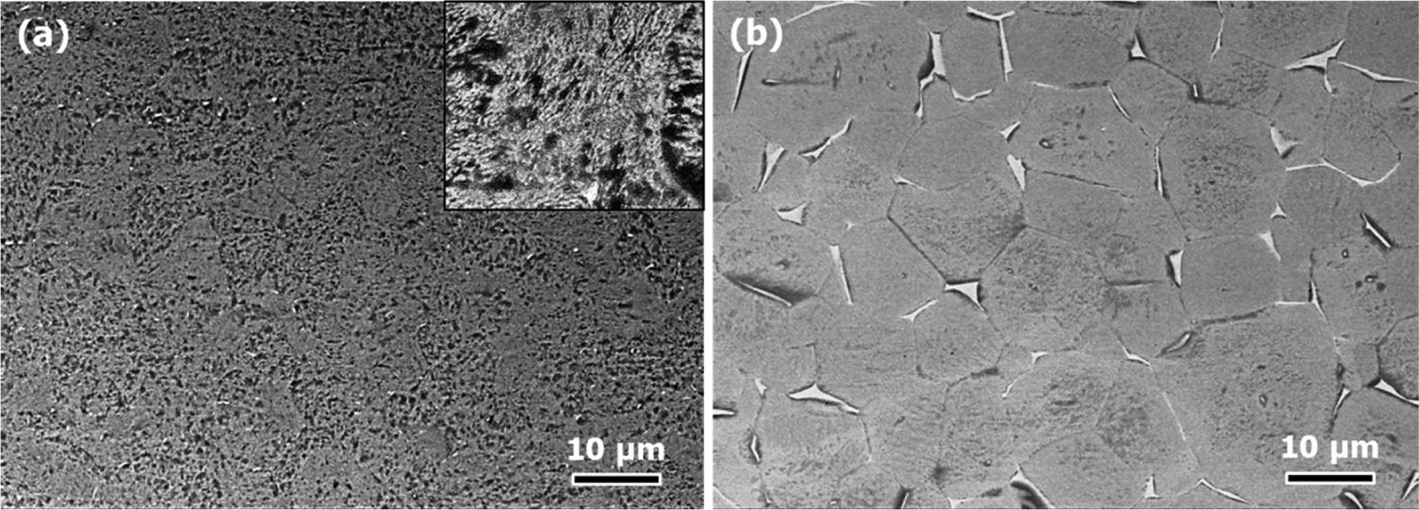
BSE-SEM images of the microstructure of Ti-3Al-2.5V: (a) as-received (inset shows a higher magnification image) and (b) after bulge forming.
Comparison of experimental and FE analysis results for thickness strain.
Experiment and FE analysis for gas blowing of tube
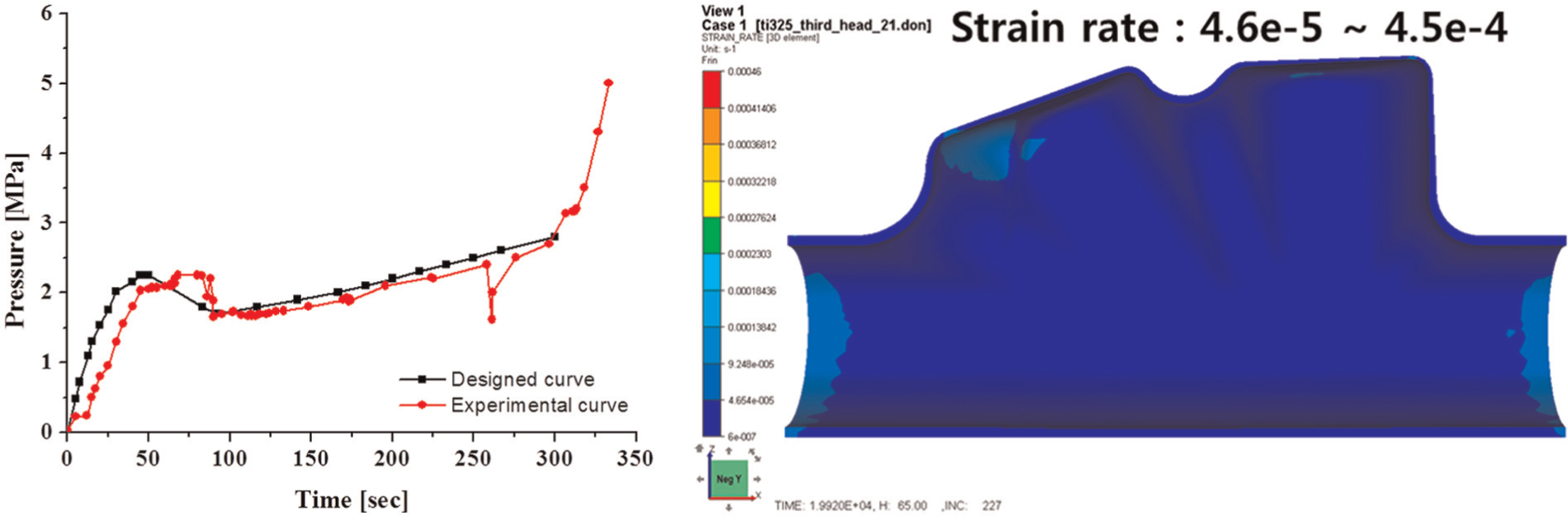
Sections “B,”“D,” and “E” were deformed to a high degree, with the thickness strain at “E” exceeding a value of 1.0, as shown in Table 2. Consequently, some failures were observed in the “E” section when the strain rate was not adequately controlled, as shown in Figure 8. Finally, a bulged tube without defects can only be fabricated if the strain rate is controlled by proper time–pressure conditions. The optimum time–pressure conditions are calculated by the flow chart as shown in Figure 9. Every strain rates are checked if the values satisfied adequate strain rate ranges (from 10e−4 to 10e−5) at each step. Figure 10 shows the optimum time–pressure curve and strain rate distribution of bulged tube. The strain rate can be controlled within the range from 4.6e−5 to 4.5e−4 s−1. The strain rate curve can be calculated by FE analysis and can therefore reduce the trial-and-error associated with obtaining difficult forming conditions. To simulate these tube bulge forming processes, Forge™ commercial software was used based on elasto-visco-plastic formulation. Figure 11 shows the distributions of thickness and equivalent strain in a bulged tube.
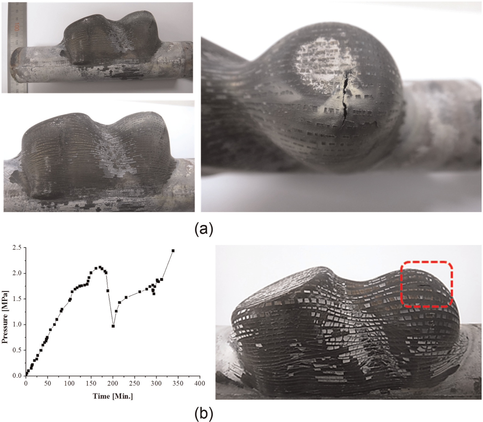
Defects caused by inappropriate strain rate control: (a) typical defects and (b) inappropriate pressure control condition and following defects.
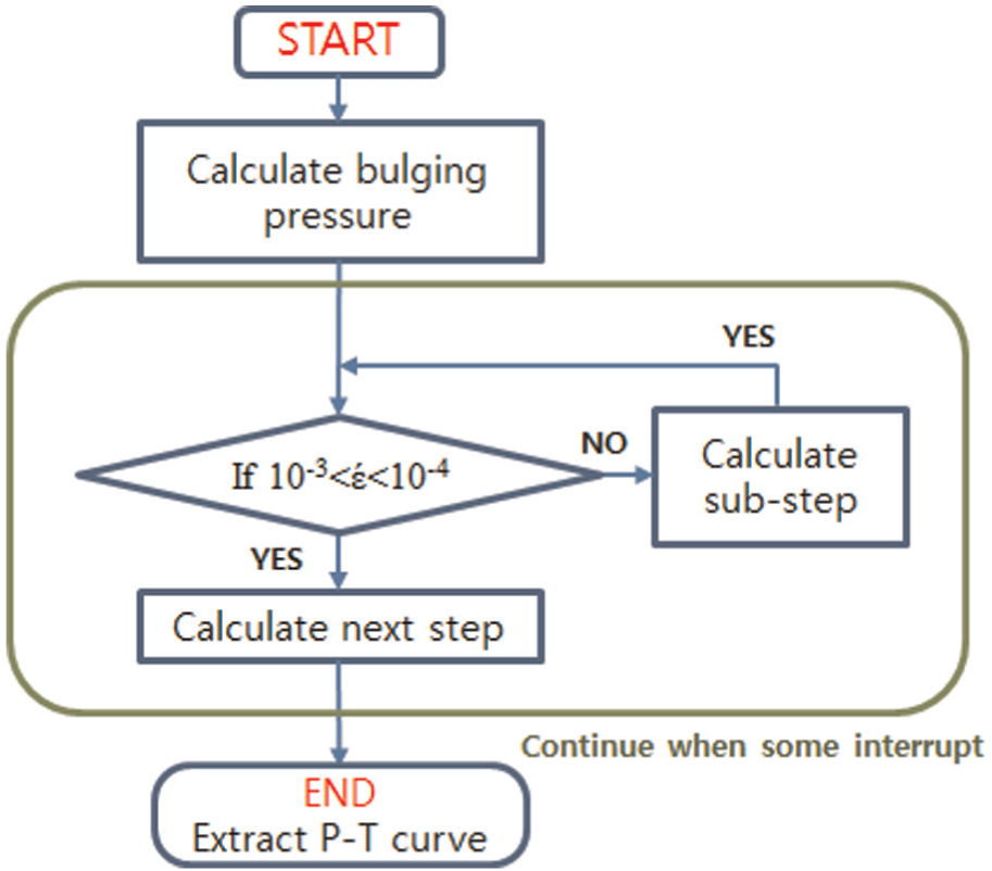
Flow chart calculating the optimum time–pressure curve.
Other defects caused by inappropriate strain rate control.
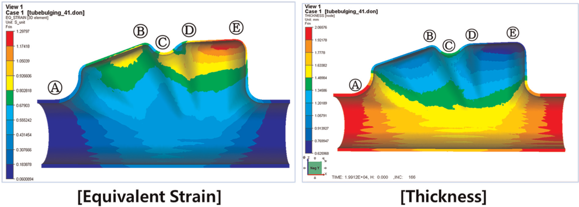
Distributions of thickness and equivalent strain for a bulged head tube.
Conclusion
The head tube is a four-directional multi-joint subjected to the highest applied external load of all parts of the bicycle. Therefore, it is desirable to establish a means to fabricate one-piece head tubes, with tube bulge forming considered as a suitable forming process. Commercial Ti-3Al-2.5V alloy tube, a standard material for Ti-alloy-body bicycles, was used for practical experimentation. FE simulation was also used to predict potential defects by inappropriate gas blowing conditions and to calculate the optimum forming conditions. As a result of both FE analysis and experimentation, an optimized pressure curve for the bulge forming of a bicycle head tube is proposed. The effect of microstructural changes by deformation was also investigated, in order to predict defects in large-scale deformation of bulged head tubes.
Footnotes
Declaration of conflicting interests
The authors declare that there is no conflict of interest.
Funding
This study was supported by a Grant from the Fundamental R&D Program funded by the Ministry of Knowledge Economy, R.O. Korea.