
Abstract
Indentation forming process is used for internal forming and sizing of thick-walled tubes working in high internal pressures. In this process, a mandrel with a diameter slightly larger than that of the tube is pressed and moved inside the tube, creating an internal profile. This article presents theoretically and experimentally influences of longitudinal ultrasonic vibration on this forming process. For this purpose, vibro-impact and continuous forming regimes have been investigated. Application of longitudinal ultrasonic vibration along the axis of the workpiece showed experimentally reduction of 15%–21% of axial forming forces and improvement of surface quality of the bore of the tube, while no effect on spring back of the formed zone was observed.
Introduction
Indentation forming process is a simple way of little forming, ironing and sizing of internal surface of thick-walled tubes. The process is carried out by pressing and driving a profiled tool (mandrel) inside the tube. Since the diameter of the tool is slightly larger than that of the tube, the surface of the tube is formed and work-hardened.
In ultrasonic-assisted forming, ultrasonic vibration with a certain amplitude and frequency is applied to a part or whole of workpiece, die, tool, or combination of them in a certain direction or directions. This vibration can reduce friction, change strength of the material (if applied to workpiece) and change the loading mechanism and consequently reduce the forming force. In addition, better surface quality, tool life enhancement, more uniform dislocation distribution, internal stress concentration reduction and dimensional and geometric stability are the expected results of employment of ultrasonic vibration. Due to the likely advantages, ultrasonic-assisted forming has been investigated during the past years.
Blaha and Langenecker 1 studied the effects of applying ultrasonic vibration on the process of forming in 1955. Their research showed the softening effect of superimposed ultrasonic vibration on zinc single crystals, which were undergoing a tensile test. In 1957, Nevill and Brotzen 2 investigated the effect of mechanical vibration in the frequency range of 15–80 kHz on the tensile elongation of low-carbon steel wires. Their experiments showed that for a variety of amplitudes, the reduction in stress was proportional to the amplitude of vibration. In 1966, Pohlman and Lehfeldt 3 studied the influence of ultrasonic vibration on plastic forming of metals. The result of an experiment on a polycrystalline copper specimen subjected to tensile deformation, while impulses of 20-kHz ultrasound were intermittently superimposed, showed that the force drop due to ultrasonic vibration was only seen in the plastic part of stress–strain curve and not in the elastic part. They concluded that application of ultrasound under suitable conditions can considerably reduce both the external and internal forces required to overcome friction forces to form plastically metallic specimens.
Atanasiu 4 investigated tube drawing by axial ultrasonic oscillation of the plug in 1980. He found that ultrasonic affects the yield limit and causes the coefficient of friction and the coefficient of viscosity to decrease. It was also observed that the reduction in drawing force is diminished at greater drawing speeds. 4 Siegert and Ulmer 5 in 2001 investigated the superimposing of ultrasonic waves on the dies in tube and wire drawing. The results showed that longitudinal oscillation of the die at ultrasonic frequencies in the range of 20–22 kHz parallel to the drawing direction could reduce the friction. The reduction of the drawing force was found to be mainly a function of the ultrasonic amplitude. It was also found that increased drawing speed could decrease the drawing force reduction, perhaps due to decrease in oscillations per unit of length. Murakawa and Jin 6 in 2001 investigated the applicability of ultrasonic radial vibrated dies in the wire drawing process. They reported that radial ultrasonic vibration application is very effective in increasing the critical drawing speed, and it is approximately 10 times as fast as that for axial ultrasonic vibration application, making the radial vibration more productive than the axial vibration.
Hung and Hung 7 in 2005 studied the influence of ultrasonic vibration on hot upsetting of aluminum alloy. Their experimental results indicated that ultrasonic vibration could considerably reduce the compressive forces needed during hot upsetting. The reducing effect on compressive forces decreased while the temperature increased. The strain rate did not significantly affect the reducing effect on compressive forces.
In 2007, Mousavi et al. 8 studied the effects of applying ultrasonic vibration on the die during the extrusion process. They showed that the extrusion force and the material flow stress would be reduced by applying the ultrasonic vibration if the extrusion speed was below a critical speed. In addition, it was found that applying the ultrasonic vibration had no significant effect on the equivalent plastic strain of the material. A larger reduction in average extrusion force was obtained by either reducing the extrusion speed or increasing the amplitude of vibration. In 2009, Hung and Chiang 9 investigated the influence of ultrasonic vibration on double backward-extrusion of aluminum alloy. The results showed that under the effect of ultrasonic vibration, the forming force would be decreased because the ultrasonic vibration increased the temperature of the workpiece.
Susan et al. 10 in 2010 researched mechanical characteristics of stainless steel tubes in the process of drawing under different drawing speeds while using ultrasonic vibration. They obtained decreased mechanical resistance, much greater extension and increase of drawing surface quality while using ultrasonic vibration.
In 2011, Pazand and Feizi 11 presented application of artificial neural networks in investigations on the effects of ultrasonic vibration on the extrusion process. Siddiq and Sayed 12 in 2012 presented a computational study of ultrasonic-assisted manufacturing processes including sheet metal forming, upsetting and wire drawing. A fully variational porous plasticity model was modified to include ultrasonic softening effects and then utilized to account for instantaneous softening when ultrasonic energy was applied during deformation. Shan et al. 13 in 2012 presented a new mathematical model of the antifriction effect on wire drawing with ultrasonic. The results pointed out that the antifriction effect of ultrasonic had observable effects on the drawing force reduction, while the drawing speed had no visible effect on the drawing force.
In this article, theoretical relations of required axial force in indentation forming process are derived under the condition of longitudinal ultrasonic vibration superimposed on the tool in axial direction. In addition, the ratio of tool speed to vibration speed is investigated. By using these relations, effects of amplitude and frequency of vibration on axial forming force can be extracted. To prove the effects experimentally, longitudinal ultrasonic vibration is applied to the workpiece along the axis, and the results are presented.
Analysis of indentation forming process
The employed model for analysis of indentation forming is shown in Figure 1. Slab method is utilized for analysis of indentation forming without ultrasonic vibration. This method is also known as the free-body equilibrium approach or the force balance method. 14
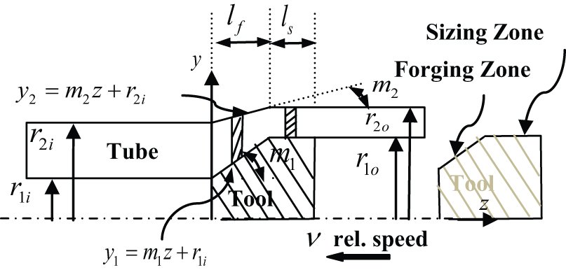
Schematic representation of tube forming without ultrasonic vibration. 14
In this process, the tool geometry consists of two parts, forging and sizing. In the forging zone, the intended internal profile of the tube is formed, and the tube inner diameter, and consequently, its outer diameter, is enlarged. In the sizing zone, both inner and outer diameters of the tube reach their final size and surface finishing is done.
The force balance method is applied on slab elements in forging and sizing zones separately under the following assumptions.
Force is applied in the axial direction to the tool for indentation and the plates perpendicular to it are the main stresses directions.
Although the friction effect on the contact surfaces of the tool and the workpiece has been considered, the influence of frictional stress has been ignored on the main stresses’ plates.
Strain in different directions is considered as a homogeneous strain at one point, but strains are distinctive at different points.
Coulomb law is dominant for friction between tool and workpiece contact surfaces.
Tresca criterion is used to determine the strength of the stress.
The force required for tube forming without ultrasonic vibration is as follows 14
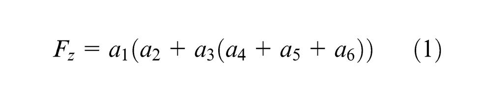
where the coefficients are 14
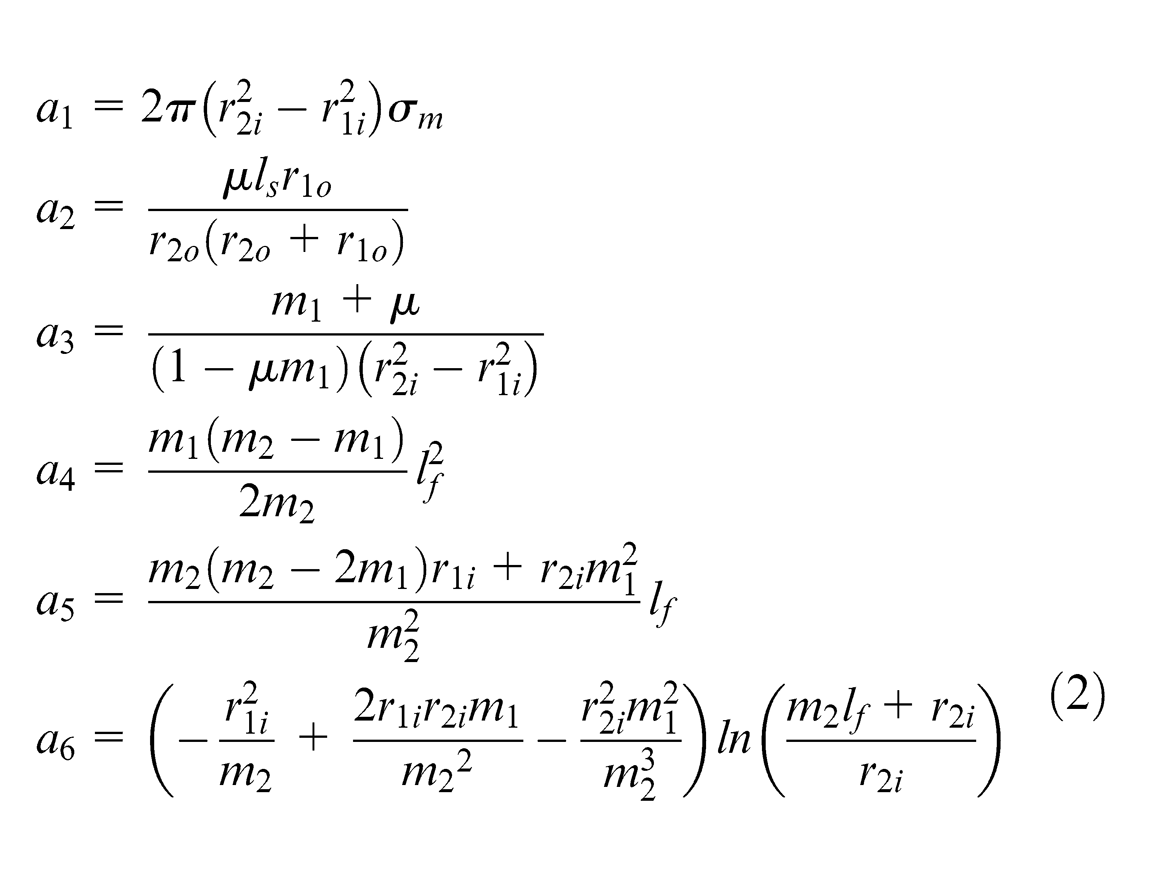
where
Longitudinal ultrasonic vibration of the tool in axial direction
In order to study the effects of vibration on the indentation forming process, the tool is axially exposed to ultrasonic longitudinal vibration. The rheological model of material is used for this analysis. This reflects its real elastic, viscous and plastic properties without consideration of hardening. In addition, it aids to describe the forming process while ultrasonic is used. This approach explains the physical mechanisms of ultrasonic effects on the processes of plastic deformation. Moreover, impulsive and continuous regimes of loading have been considered in this analysis.
15
For continuous regime of deformation (Figure 2(a)), the contact between the tool and tube is always preserved and there is no separation, while for impulsive regime, there is a cutoff and separation for a short time (Figure 2(b)). For
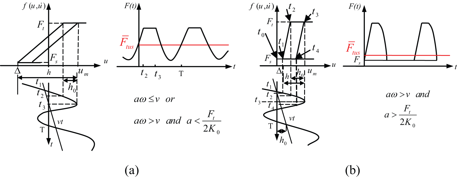
Schematic representation of (a) continuous loading situation and (b) impulsive loading situation. 15
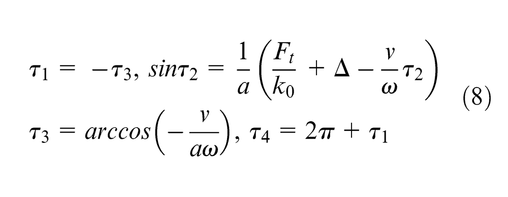
Impulsive loading situation within an ultrasonic oscillating period is as follows
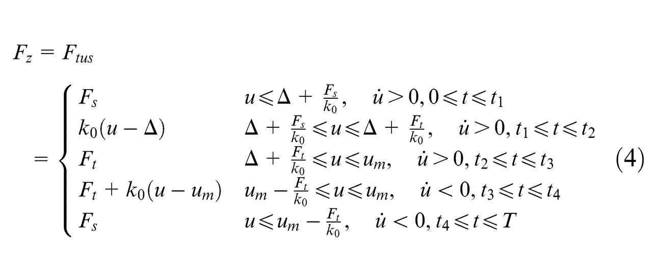
where

In equation (5),
where
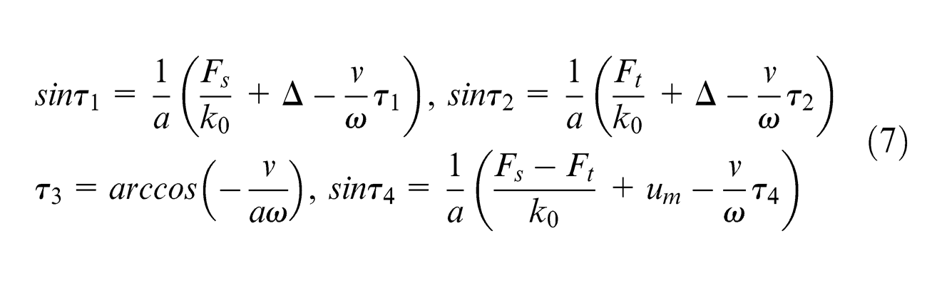
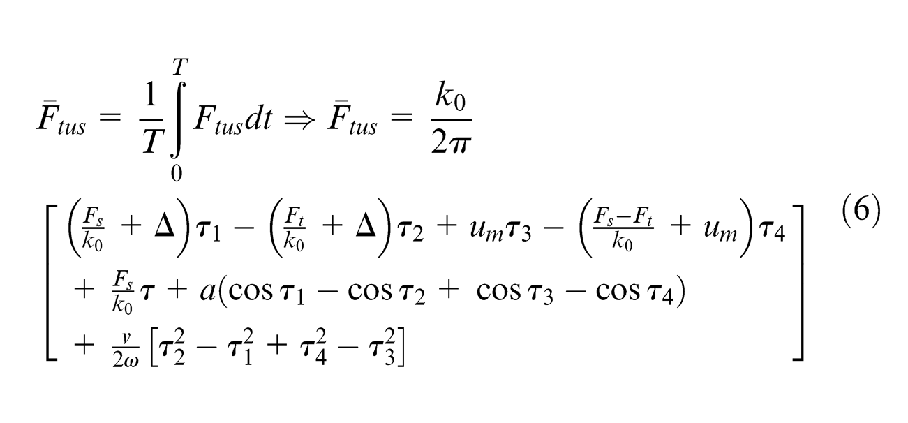
For continuous regimes of deformation, the same relationships as equations (4)–(6) are valid if the following substitutions are used
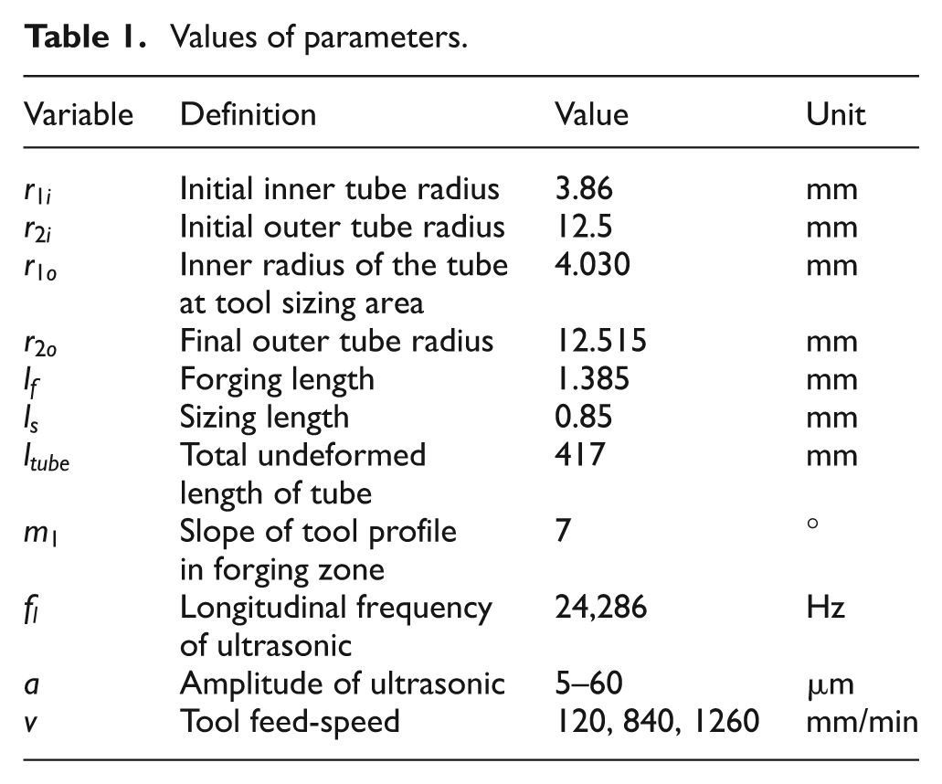
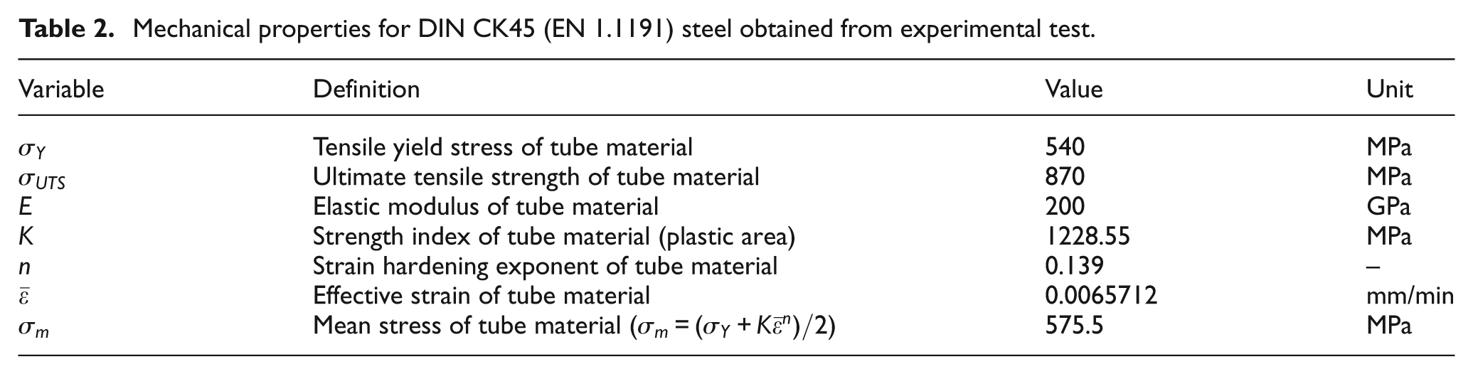
The required values of parameters in experimental tests have been shown in Table 1. The tube material was DIN CK45 (EN 1.1191), and its properties have been obtained by experiment (see Figure 3 and Table 2). After substituting these values in equations (1) and (6), the required forming force with and without ultrasonic in different vibration amplitudes and speed ratios
Values of parameters.
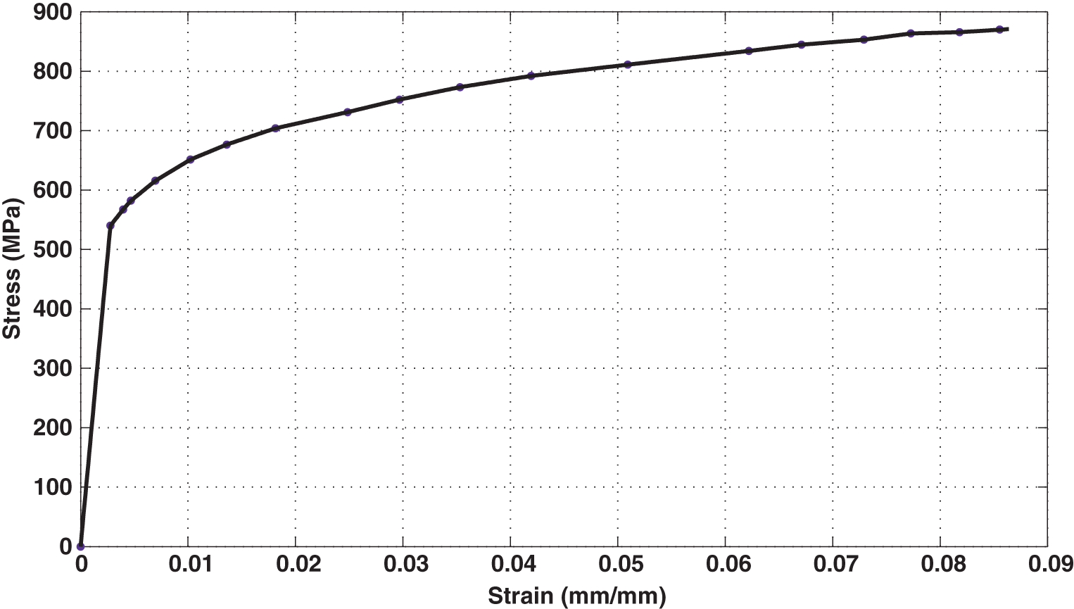
Experimental stress–strain curve for DIN CK45 (EN 1.1191) material used in the experiments.
Mechanical properties for DIN CK45 (EN 1.1191) steel obtained from experimental test.
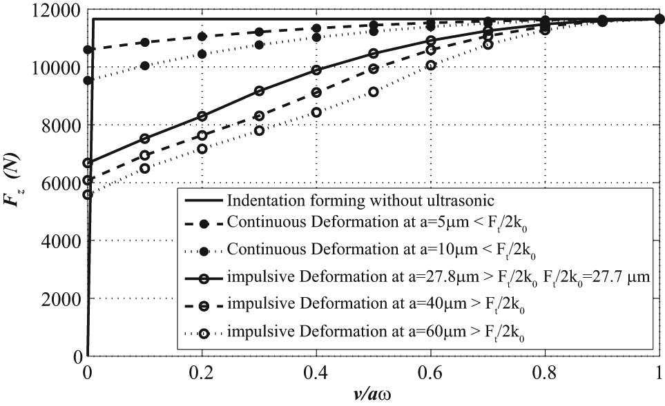
Variation of axial forming force for conventional and axial longitudinal ultrasonic tool vibrations in continuous and impulsive regimes against speed ratio at different vibration amplitudes based on theoretical relations.
Experimental setup
To verify the theoretical relations with and without employment of ultrasonic vibration, CK45 steel tubes, with the specification given in Table 1, were formed by using tungsten carbide indentation tool shown in Figure 5.
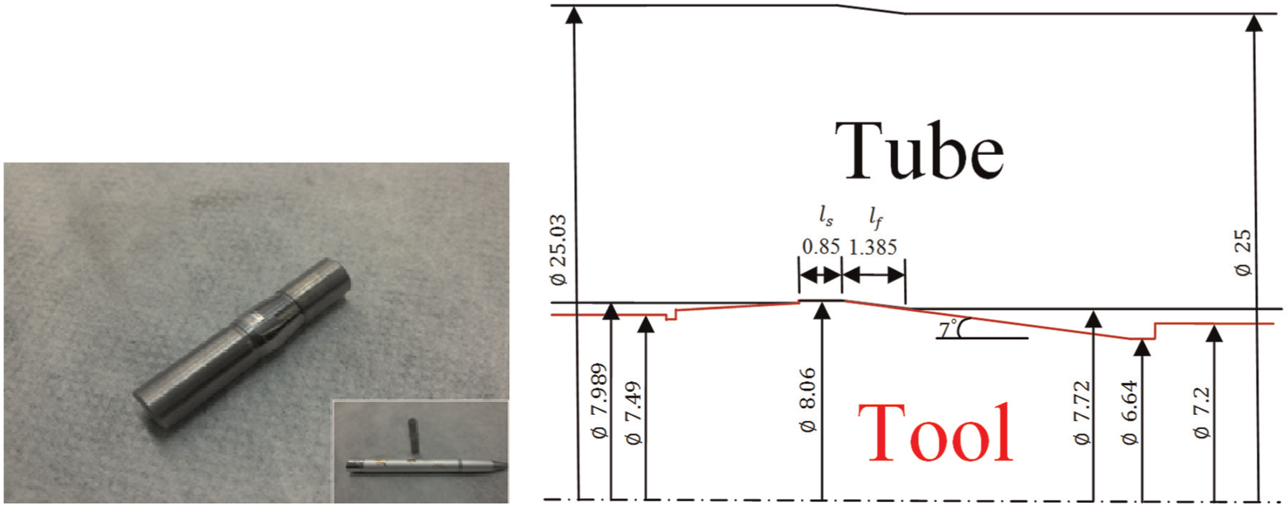
View and drawing of the indentation forming tool and the tube before and after forming.
A setup consisting of a forming machine body, a hydraulic jack for tool feed, a tool feed driving rod, fixed and movable constraining holders, ultrasonic system and dynamometer were prepared. Figure 6(a) shows a picture of the whole system assembled and schematic representation of the system.
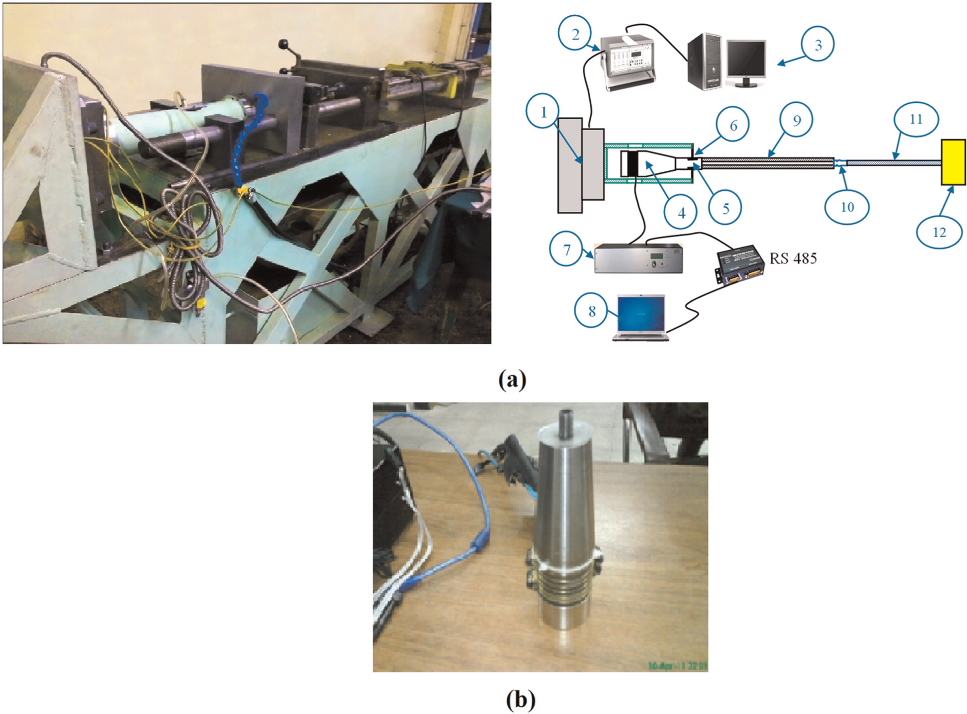
(a) Indentation forming machine with axial longitudinal vibration of the workpiece tube and force measuring dynamometer and (b) piezoelectric transducer with 3 kW power.
Machine body was fabricated from a welded structure with some adjustable bolted parts for holding and supporting the dynamometer, ultrasonic system assembly, workpiece tube and tool driving system. The constraining holders were made from thick squared steel blocks to prevent misaligning of the workpiece tube and the tool feed system during forming process. Ultrasonic system consisted of a 2-kW power supply made by MPI of Switzerland, 16 a designed and fabricated 3-kW piezoelectric ultrasonic head for longitudinal vibration (Figure 6(b)) and a titanium matching and titanium connecting part between the ultrasonic head and the workpiece for transferring ultrasonic vibration to the work tube (not to the tool). In addition, the titanium connecting part was fixed on its vibration node to support and bear the axial forming force. The fixing body holding the titanium connecting part was standing on a dynamometer system from Kistler (Type 9255B), 17 which can measure normal compressive forces up to 40 kN. The dynamometer was further supported by an adjustable strong welded square connected to the machine body by bolts.
The dynamometer is connected through interfacing unit to a computer, and the forces exerted on the dynamometer in three normal directions can be monitored and drawn against time by using DynoWare software. The MPI ultrasonic power supply to the transducer is also connected to a computer and is driven and controlled by LabVIEW from National Instrument. The amplitude and power of vibration can be adjusted in the software, and the resonance frequency of the whole system assembly is automatically measured and readjusted every 10 ms by the software/hardware of power supply.
Effect of ultrasonic power given to the workpiece on the forming force
If vibration frequency and tool feed-speed are constant, period of imposed plastic deformation exerted by the tool on the workpiece tube decreases within a period of vibration if vibration amplitude is increased. This is proved in Figure 7 in which three experimental graphs are presented. When no ultrasonic is used, the force curve stands at highest level along the whole length of the tube. At 956 W power of ultrasonic, it stands lower, and at 1705 W, it is the lowest. Decrease of 21% of axial force could be achieved in these tests. Theoretical graphs of 0, 5
Influence of power of ultrasonic vibration on the axial forming force at tool feed-speed of 840 mm/min in various experimental powers of 0, 956 and 1705 W and in excitation frequencies of 25,726 and 24,748 Hz (given to the workpiece). Theoretical curves for axial vibration of the tool are also presented with ultrasonic amplitudes of 0, 5, 10, 27.8, 40 and 60 µm in resonance frequency of 24,286 Hz (in the theoretical ones
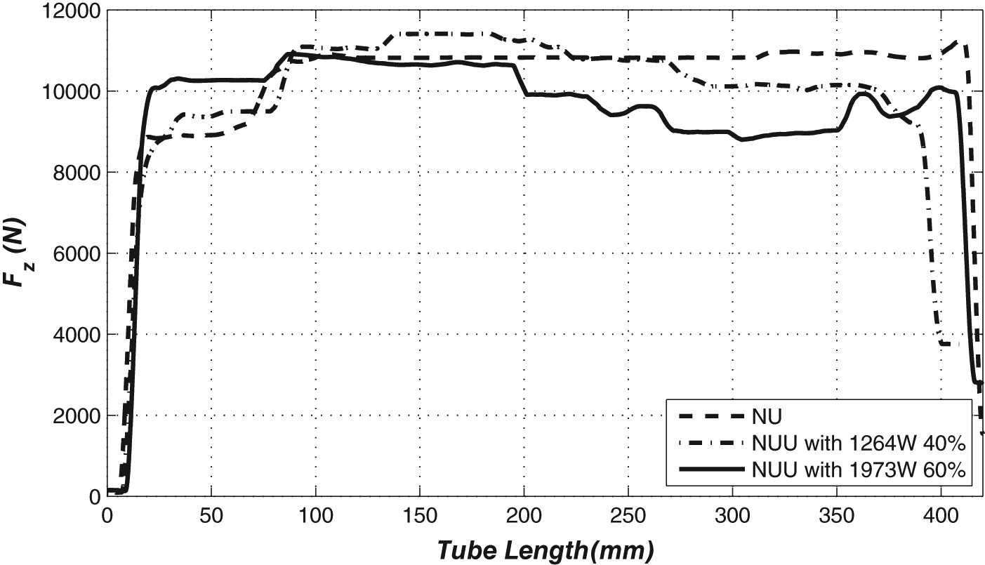
Influence of power of ultrasonic vibration given to the workpiece on the axial forming force at tool feed-speed of 1260 mm/min in various ultrasonic powers; 0 (NU) over the whole length of the tube; 1264 and 1973 W (NU-U) switched on over the second half of the length of the workpiece tube (excitation frequencies of 25,681 and 24,897 Hz respectively).
Effect of ultrasonic vibration of the tube workpiece on the bore dimension
The formed tube has two inner diameters (Figure 9(a)): base and formed circle diameters. The former is approximately equal to the initial inner diameter of the tube, and the latter is close to the tool sizing area diameter. It must be mentioned that before doing the tests, tubes were cleaned by ultrasonic cleaner for 10–15 min and then cleaned using alcohol and maintained in silica gel for moisture control. Two methods have been used to measure the tube bore dimensions.
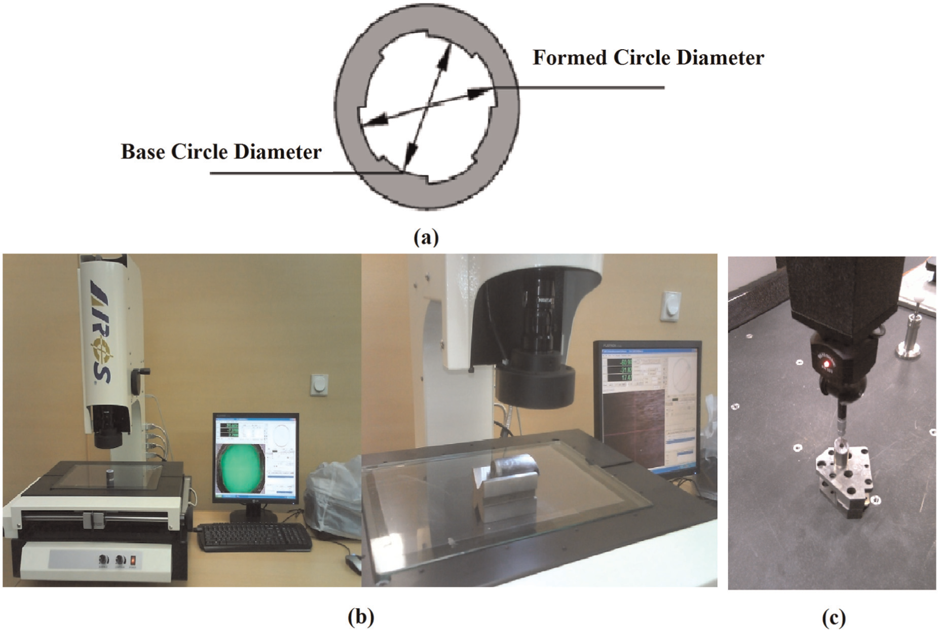
(a) Schematic of tube inner diameters, (b) video measuring machine with 1 µm resolution and (c) view of coordinate measuring machine with specimen separated from the formed tube.
Video measuring machine
Video measuring machine (VMM) operation is based on identification of dark and light boundaries; therefore, sharper edges of measuring surface improve the measurement accuracy. For using this method, small pieces of sample were cut carefully normal to the axis of the tube, and they were ground finely with burrs removed by emery cloth and then washed and dried before measurement. The pieces were placed on the VMM (KIM-CU Series; ARCS, Taiwan) table, and through adjusting its focal point and lighting, four suitable points on formed circle were selected to determine the diameter.
Percentage of spring back can be calculated from the following relation
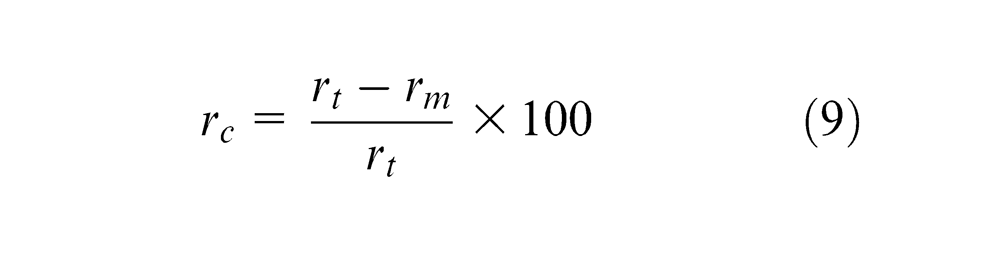
where
Table 3 shows the value of spring back for the formed circle obtained by VMM with and without ultrasonic application. Ultrasonic power for the test was set at 1186 W with frequency of 25,613 Hz at 1260 mm/min tool feed-speed.
Percentage of spring back determined by two measuring methods (VMM and CMM) in the formed zone for specimens formed with 1186 W axial longitudinal ultrasonic vibration of the workpiece and without vibration at 1260 mm/min tool feed-speed.
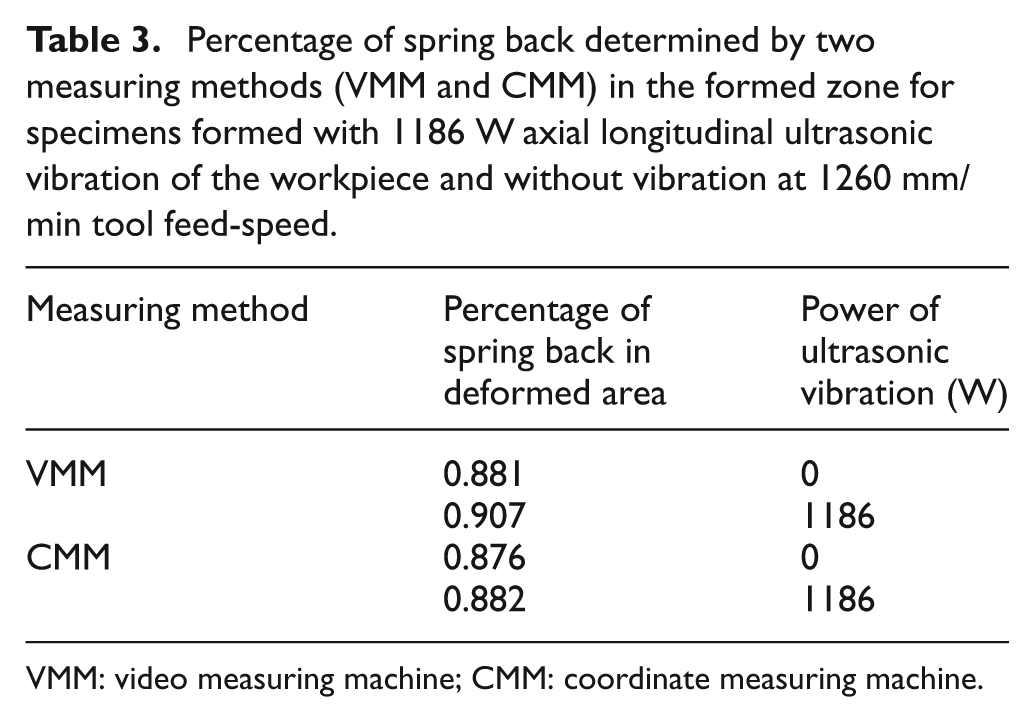
VMM: video measuring machine; CMM: coordinate measuring machine.
As in the explained measuring method, human error in selecting the points (dark and light boundaries) is very effective; the calculated percentage value may be affected. To have more secure results, an alternative measuring method was also used as follows.
Coordinate measuring machine
The coordinate measuring machine (CMM) used in this study (Bridge Type; Leader Metrology Company, China, 2009) 18 has Renishaw PH10T head and Renishaw TP20 probe with 2 mm diameter stylus (Figure 9(c)). The ruby tip of stylus makes contact with the inner surface of the samples prepared from the tube, and by selecting four sample points around the formed circle, the circle diameter was determined. Measurements were performed three times in five sections, and the results given in Table 3 are the average of 15 repetitions with ±0.2% of coefficient of variation. The measurement results of this method are also shown in Table 3. It is obvious that there is no significant effect from ultrasonic vibration on the spring back of the tube.
Effect of axial ultrasonic vibration given to the workpiece on the inner surface quality of the formed tube
In order to investigate the effect of ultrasonic vibration on the inner surface quality of the formed zone, two sections of a tube in which ultrasonic vibration was applied for only the second half of its length were cut: one section at the middle of the place without application of ultrasonic and one section at the middle of the place formed under ultrasonic vibration. The pieces separated from the tube were halved along the axis in order to be able to see the deformed bore surface of the tube. Before viewing, the pieces were washed and dried. Figure 10 shows the surface quality of the two sections by using the optical measuring device (VMM). This figure reveals that the presence of ultrasonic vibration improves inner surface quality of the formed tube. In fact, creating a homogeneous surface pattern is one of the advantages of ultrasonic vibration. Although the surface of the tool was fully polished to mirror finish, traces of scratches are evident in Figure 10(a) in the form of vertical lines. Ultrasonic vibration significantly reduces these traces.
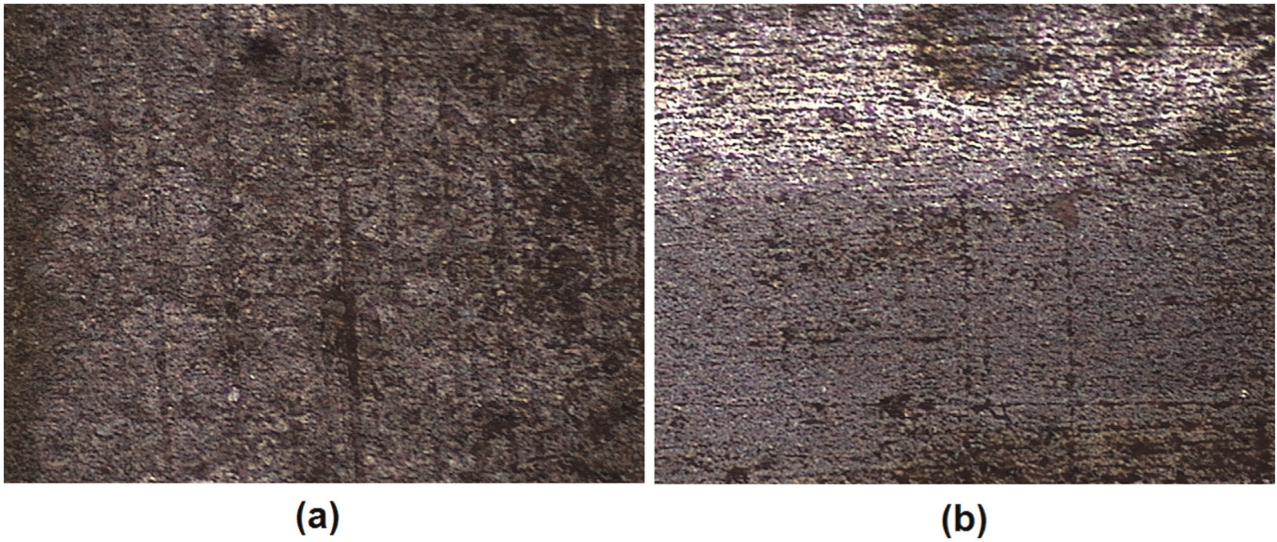
Effect of axial longitudinal ultrasonic vibration of the tube on surface quality of the formed zone at 1260 mm/min tool feed-speed (a) without ultrasonic vibration and (b) in the presence of ultrasonic vibration with frequency of 25,681 Hz and power of 1.2 kW.
Results and discussion
Based on the findings of Figure 4, vibration amplitude and the ratio of tool feed-speed to amplitude of vibration speed have a significant influence on mechanism of process and on the forming force. Theoretical study shows that increase of the latter cause decrease of ultrasonic effect and thereby increasing forming forces. At unity, the effect of ultrasonic vibration is completely eliminated and the forming force will be equal to operation without ultrasonic.
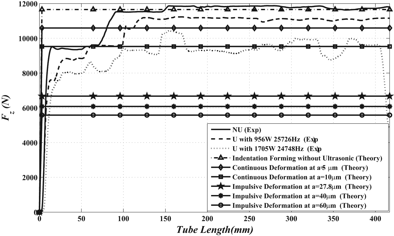
Experimental results with and without axial longitudinal ultrasonic vibration of the tube and theoretical results of applying axial longitudinal ultrasonic vibration to the tool in various amplitudes of vibration (0, 5, 10, 27.8, 40 and 60 µm) have been shown in Figure 11. According to the theoretical relations, in the vibro-impact regime, the axial forming force reduction is approximately 50% (5602 N in the presence of ultrasonic vibration of 60 µm amplitude). In continuous regime of 10 µm amplitude, the theoretical reduction is about 18% (9589 N). In experimental tests, maximum axial forming force reduction is about 21% (9249 N) when ultrasonic vibration of 1705 W power at frequency of 24,748 Hz and tool feed-speed of 840 mm/min is used. Therefore, comparing the experimental and theoretical results, it shows that the loading regime is continuous in experimental tests, that is, during the ultrasonic vibration, tool and tube are in continuous contact in the whole vibration period and no separation occurs.
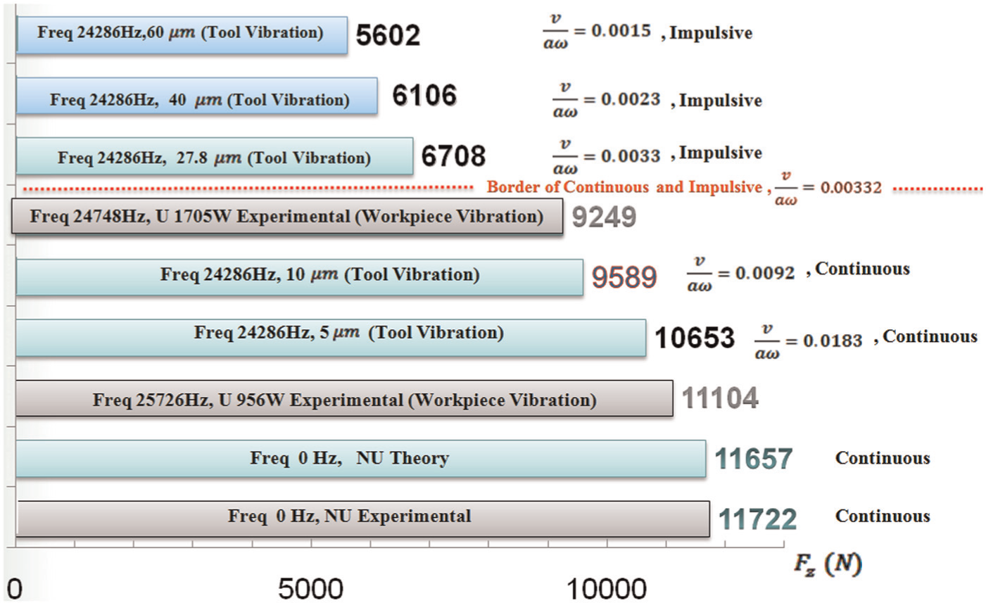
Comparison of theoretical and experimental axial forming force at ν = 840 mm/min tool feed-speed for DIN CK45 (EN 1.1191) steel tube as workpiece.
It should be mentioned that during experimental tests, the longitudinal vibration has been applied to the workpiece, and the tool was forced to go ahead by a separated rod (no pulling was possible by the rod). In practice, due to limitations of tool feed-speed in the present experimental equipment, it was not possible to investigate the effect of the speed ratio (tool feed-speed over vibration speed amplitude) on the forming force. The amount of experimental axial forming force reduction in the presence of ultrasonic vibration was determined about 2–3 kN (15%–21%). It is expected that there was no separation between the tool and the workpiece and forming was of continuous type, these effects can be attributed to two dominant phenomena.
Nature of indentation forming process when the workpiece tube is longitudinally vibrated
In present experimental studies, feed force was transferred to the tool by a disconnected feeding rod pushing the tool only in one direction (ahead) inside the workpiece tube along the whole length of the tube.
By considering
The second, if the workpiece spring back was lower than twice the amplitude of longitudinal vibration given to the workpiece
It must be noted again that in our real case, the longitudinal vibration was given to the workpiece and the tool was driven forward by a disconnected rod, which was touching the back of the tool and pushing the tool ahead. Under this condition, even at low spring backs of the workpiece, the tool does not separate from the workpiece under any circumstances, but the hammering effect of the feeding rod still can occur if the condition of
In our experiments, comparison of theoretical and experimental results (Figures 4 and 7) shows that the condition of
Effects of frictional forces, acoustic softening, local temperature rise at discontinuities and material structural changes
Friction forces and friction coefficient is another issue, which can be influenced by vibration given to the workpiece tube. This not only can reduce Coulomb friction coefficient from static to dynamic in contact zones between the workpiece tube and the tool in forging and sizing areas but also can have influence on shearing stresses in shearing layers inside the workpiece body at deforming zones.12,19–22
Acoustic softening of the workpiece material is another probable effect in which, on one hand, at the discontinuities (at grain and crystal boundaries), concentrated and localized softening heat is generated, and on the other hand, dislocations are stimulated and activated. Therefore, these dislocations can easily migrate within the structure of grains and do not stop at grain boundaries, penetrating inside other grains without serious resistance.12,19–22
Local contact temperature rise at contact zone of the tool and workpiece is the result of transmission of acoustic waves from the workpiece to the tool, and this phenomenon gives rise to local thermal softening of the workpiece material, which can be influential on reduction of forming forces.12,19–22
Some research sources claim that dynamic recrystallization can be responsible for material behavior changes against deforming forces. 23 Others discuss about dynamic recovery and adiabatic shear banding within the material.23–26
Under high-frequency vibration of ultrasonic, material stiffness is no longer a pure function of static stiffness. The so-called dynamic stiffness is a function of static stiffness, mass, structural damping and excitation frequency, and this gives rise to changes in resistance of the workpiece material.
Superposition of internal residual stresses with stresses created by ultrasonic action can have an impact on resistance of material against induced forming forces.1,3,5,19
Unfortunately, the force monitoring system (Kistler, Type 9255B) has a maximum response speed of 1 kHz, and it is not able to show the force variation within a cycle as the variation frequency is much higher (about 25 kHz). Therefore, it has an averaging effect on the force. Otherwise, the said mechanisms in part 1 could be analyzed experimentally.
Conclusion
In this article, theory of ultrasonic-assisted indentation forming process (axial longitudinal vibration given to the tool) has been studied, and the corresponding analytical relations have been derived. In addition, for comparison purposes, experimental tests have been performed under axial longitudinal ultrasonic vibration given to the workpiece. According to the theoretical and experimental findings, the following conclusions can be made.
Longitudinal ultrasonic vibration given axially to the tool or workpiece could reduce the axial forming forces. Ratio of tool feed-speed to vibration speed amplitude has a significant influence on mechanism of process and on the forming force. Theoretical study shows that its increase cause decrease of ultrasonic effect and thereby increasing forming forces. At unity, the effect of ultrasonic vibration is completely eliminated, and the forming force will be equal to operation without ultrasonic.
According to the theoretical relations, to have an impulsive loading (periodic separation of tool and tube), the amplitude of vibration should be greater than half of the elastic spring back.
Comparison of the axial experimental forming force reduction (under ultrasonic) with the theoretical results shows that the loading regime of experiments is similar to continuous loading.
Apart from influences of longitudinal ultrasonic vibration on relative displacements of the tool and workpiece, departure from static to dynamic friction at contact zones of the tool and workpiece and within deforming shearing layers of the workpiece, acoustic softening, dynamic recrystallization, dynamic recovery, adiabatic shear banding, dynamic stiffness and superposition of stresses can be responsible for axial forming forces variation. Local temperature rise resulted at discontinuities by ultrasonic and thereby material thermal softening at contact points of the tool and the workpiece can be another cause for forming force reduction.
Observations show that ultrasonic vibration improves forming surface quality.
According to the experimental analysis, ultrasonic vibration has no significant effect on the tube spring back.
Footnotes
Declaration of conflicting interests
The authors declare that there is no conflict of interest.
Funding
This research received no specific grant from any funding agency in the public, commercial or not-for-profit sectors.